What is a Strain Gauge? Working, Types, and Selection
Learn how strain gauges work, their types, Wheatstone bridge circuits, and how to select and install the right one for your application.

17 Aug, 2026. 22 minutes read
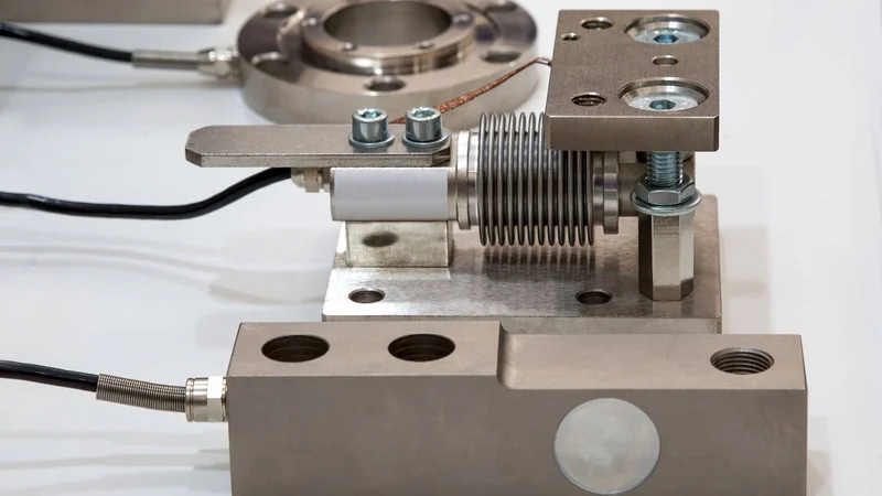
Strain gauges for ring (membrane), bellows and beam type weighing equipment.
Key Takeaways
A strain gauge measures strain by converting the deformation of a bonded metallic foil grid into a proportional change in electrical resistance, described by the gauge factor. 2
Metallic foil gauges have a gauge factor typically about 2, ranging up to 5 for some alloys. Semiconductor strain gauges reach 100 or more because the piezoresistive term dominates.7
The resistance change is tiny. A 350 ohm gauge at 500 microstrain shifts by about 0.35ohm, which is why a Wheatstone bridge circuit is used.3
Temperature effects are one of the dominant error sources. Self-compensated gauges, half-bridge or full bridge wiring, and three-wire hookup remove most of it.4
Gauge selection is a set of linked choices: gauge length, resistance (120 ohm vs 350 ohm), alloy, carrier, and the self-temperature-compensation number matched to your material. 1,9,10
Introduction
If you need to know the actual stress in a bracket, a pressure vessel, or a bridge girder, you cannot measure stress directly. You measure strain and calculate stress from it.11 The strain gauge is the sensor that makes this practical, and it has been the dominant tool for the job since 1938. 12,13
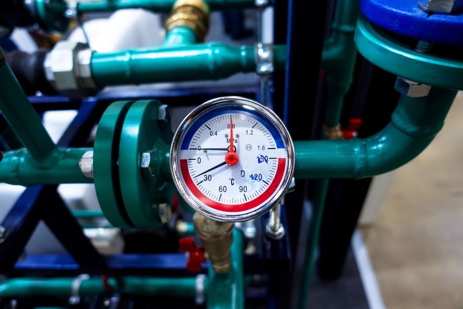
The principle is simple enough to state in a sentence: stretch a conductor and its electrical resistance rises. Turning that into a trustworthy measurement is where the engineering lives. The resistance changes involved are on the order of 0.1%, and a few degrees of temperature drift can swamp the signal you actually care about.3,4
This guide walks you through the working principle of strain gauge, gauge factor, types, Wheatstone bridge configurations, temperature compensation, and a practical checklist for selecting and installing the right strain gauge for your application.
What Is a Strain Gauge?
A strain gauge is a resistive sensor: its electrical resistance changes in proportion to the mechanical strain applied to it. 2 The gauge itself does not measure applied force or stress directly; it measures the resistance change (ΔR/R), which is then related to strain through the gauge factor. 7 The most common form is a thin metallic foil etched into a grid pattern and bonded to a flexible carrier, which is in turn adhered to the surface of the part under test.6
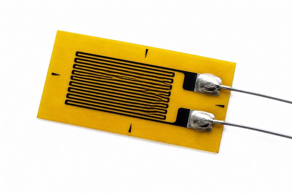
The grid pattern is not decorative. It maximizes the amount of metallic foil aligned with the strain direction while keeping the overall footprint small, which is what gives the gauge its directional sensitivity. 10
When the part under test is loaded and deforms, the bonded gauge deforms with it. This changes both the length and cross-sectional area of the sensing element, which changes its resistance. That resistance change is what the instrumentation, typically a Wheatstone bridge, converts into a measurable electrical signal.
Construction of a Strain Gauge
A strain gauge is built as a three-layer laminate:
Base layer: A flexible, electrically insulating polymer film, usually polyimide, forms the bottom of the stack. 6 This is what actually contacts the test part, held in place with a structural adhesive (commonly cyanoacrylate). Its job is purely mechanical, transferring the part's surface strain up into the foil grid without adding stiffness of its own.
Sensing layer: Sitting on top of the base is the resistive element itself; a metal alloy foil, typically constantan or karma, chemically etched into a zigzag grid rather than left as a straight strip.2,10 The zigzag matters: it packs a long effective length of foil into a small physical area, and that length runs parallel to the direction you want to measure, which is what makes the gauge sensitive to strain along one axis rather than reacting equally in every direction.
Cover layer: A thin protective laminate is applied over the grid, shielding it from moisture, dust, and abrasion while adding a further layer of electrical insulation. This layer stops short of the solder tabs, leaving them exposed for lead attachment.
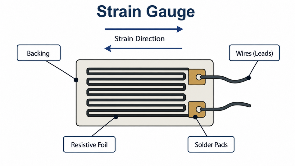
At each end of the grid, the foil widens into solder tabs; the exposed pads are left outside the encapsulation, where lead wires are soldered on. Standard gauges are commonly available in 120 Ω, 350 Ω, or 1000 Ω, with 350 Ω now the most widely used default in modern instrumentation.10
Strain, and Why You Measure It
Strain is a measure of deformation. When a part is pulled, bent, or compressed, its dimensions change slightly, and strain is simply the ratio of that change in length to the original length. Because it is one length divided by another, strain has no units of its own.
In real structures, elastic strains are tiny, often a fraction of a percent, so quoting strain as a decimal or percentage gets unwieldy. Engineers instead use microstrain, where 1 microstrain equals one millionth of the original length, or 1 x 10⁻⁶.
Stress, the internal force per unit area inside the material, is calculated afterward using Hooke's law, which states that stress equals the material's Young's modulus multiplied by strain, as long as the material stays within its elastic range.11
This is why strain measurement is so central to mechanical design validation. Once you know a material's Young's modulus, a single strain reading converts directly into a stress value.
Strain gauges are used two ways in practice: as standalone sensors bonded directly to a structure for stress analysis, and as the internal sensing element inside transducers such as load cells, where the gauge is bonded to an engineered spring element and the whole assembly is calibrated as one unit.9
Strain Gauge or Strain Gage?
Both spellings are in active use and refer to the same device. "Strain gauge" is the standard international spelling, while "strain gage" is the conventional spelling in the United States, particularly in manufacturer documentation and ASTM standards. 1,2
Vishay Micro-Measurements uses "strain gage" throughout its catalog and technical notes, and the ASTM standard is titled with "strain gages." 1,2 You will need to search both spellings when hunting for datasheets. Nothing technical distinguishes them.
How a Strain Gauge Works: The Gauge Factor
The gauge factor (GF, or k) is the single most important specification on a strain gauge datasheet. It is the ratio of fractional resistance change to strain 7:
GF = (ΔR/R) / ε
Expanded into its physical contributions, the gauge factor is 7:
GF = 1 + 2ν + (Δρ/ρ)/ε
The three terms are distinct mechanisms:
The geometric term (1) comes from the conductor getting longer as it stretches.
The Poisson term (2ν) comes from the conductor getting thinner at the same time, reducing cross-sectional area. For a metal with a Poisson ratio around 0.3, this contributes about 0.6.
The piezo-resistive term comes from the material's bulk resistivity changing under strain.
For constantan, the most commercially popular alloy, the piezo-resistive effect accounts for roughly 20% of the gauge factor, which lands a little above 2. 1,7 In silicon, the piezo-resistive term dwarfs the geometric terms entirely, which is why semiconductor strain gauges behave so differently.
Why the Signal Is So Small
Work the numbers for a realistic case. Take a 350 ohm foil gauge with k = 2.05, bonded to a steel member strained to 500 micro strain:
ΔR = R × k × ε = 350 × 2.05 × 500 × 10⁻⁶ = 0.359 ohm
That is a 0.1% change in electrical resistance. You cannot read that reliably with an ohmmeter in the presence of lead resistance and thermal drift. Relative resistance changes in strain gauge work are typically in the range of 10⁻⁴ to 10⁻² ohm/ohm, and resolving them accurately is exactly the problem the Wheatstone bridge circuit solves. 3
Types of Strain Gauges
Strain gauges are classified along four independent dimensions: the material of the sensing element, how that element is physically constructed, how it is mounted to the test part, and the underlying physical principle it relies on to detect deformation. A single real gauge is a specific combination of choices across all four, not a member of one category alone.
By Material
Metallic Foil Strain Gauges
The metallic foil strain gauge is the most widely used strain sensor type, and the default choice for both general stress analysis and most load cell and transducer designs. Alloy choice sets the temperature range and fatigue behavior 1:
Alloy | Character | Typical use |
Constantan (copper-nickel) | Good fatigue life, high elongation, self-compensation available | General-purpose static and dynamic stress analysis |
Karma (nickel-chromium) | Better stability over a wide temperature range, improved fatigue life | Wide temperature range, long-term static measurement |
Isoelastic (nickel-iron) | High gauge factor, extended fatigue life, very high thermal output | Dynamic strain only, not static |
Isoelastic gauges illustrate a real trade-off. Their high gauge factor and endurance make them excellent for dynamic strain, but their thermal output is so large that they are not normally used for static measurements. 1
Temperature capability depends less on the alloy alone than on the full gauge construction, alloy, backing, and lead wire attachment together. Base constantan gauges on polyimide backing run -75°C to +175°C normally, extending to -195°C and +205°C for short-term excursions. Base Karma gauges cover a similar range, -195°C to +175°C normally, with a slightly higher short-term ceiling of +205°C. Adding full encapsulation and high-endurance lead wires pushes each alloy considerably further: encapsulated constantan reaches +205°C continuous and +260°C short-term, while encapsulated Karma reaches +290°C continuous and +400°C short-term, the widest range of any general-purpose gauge construction. 1
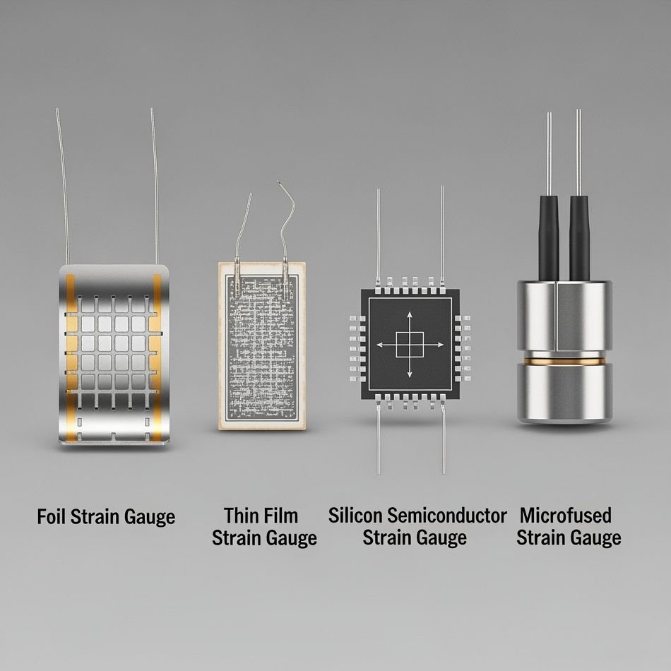
Semiconductor Strain Gauges
Semiconductor strain gauges use doped silicon instead of metal. Their gauge factors are dramatically higher: single-crystal silicon ranges from -125 to +200 depending on doping and crystal orientation, against 2 to 5 for metal foil.
That sensitivity comes at a cost. Semiconductor gauges are more expensive, considerably more temperature-sensitive, more nonlinear, and physically more fragile than foil gauges. They earn their place in miniature pressure sensors and MEMS devices, where the higher output justifies the added compensation effort.
Recommended Reading: Silicon Semiconductor: A Comprehensive Guide to Silicon and its Use in Semiconductor Technology
Emerging Flexible Strain Sensors
Research-grade flexible strain sensors push sensitivity much further. A silver/PDMS composite sensor reported in Scientific Reports achieved a gauge factor of 939 at 36% strain and survived tensile strains up to 50%, targeting human motion monitoring and soft robotics. 8
These devices operate at tens of percent strain, whereas conventional metal foil gauges are designed for elastic strains typically well below 1%. They are complementary to, not replacements for, conventional gauges in structural work.
Micro-fused Construction
A related, adhesive-free technique used specifically with semiconductor sensing elements, most often in pressure transducers. Rather than depositing the sensing material directly as with thin-film construction, a micro-fused gauge fusion-bonds a silicon sensing die directly onto a metal diaphragm using a glass-frit or similar high-temperature fusion process, eliminating the organic adhesive layer entirely.
By Construction
Independent of alloy choice, the sensing element itself can be built three different ways.
Wire-Wound Construction
The original technology, using a length of fine resistance wire looped into a grid pattern.
Foil Construction
The current default. A thin metal foil is photo-etched into a grid pattern and laminated to a flexible carrier, giving better heat dissipation, tighter geometric control, and longer fatigue life than wire ever achieved.
Thin-Film Construction
Thin-film construction departs from both wire and foil: the sensing material is sputtered or vacuum-deposited directly onto the test surface itself, only micrometers thick, with no separate carrier and no adhesive layer at all. This eliminates the temperature ceiling imposed by any bonding agent, which is why thin-film gauges using alloys such as palladium-chromium or nickel-chromium have been used in turbine and jet-engine blade testing at temperatures from 900°C up to and beyond 1100°C, well past what a bonded gauge of any alloy can survive.
By Mounting
Bonded Gauges
Bonded gauges are cemented directly to the test surface with adhesive, and this is the category virtually every gauge discussed elsewhere in this guide falls under, regardless of material or construction.
Unbonded Gauges
Unbonded gauges work differently: a pre-tensioned wire is strung between a fixed frame and a movable element, with no adhesive anywhere in the assembly. This construction is used almost exclusively inside transducers, particularly pressure and acceleration sensors, rather than for general surface stress analysis.
Weldable Gauges
Weldable gauges sidestep adhesive bonding altogether. A foil or wire sensing grid is pre-mounted and encapsulated on a small metal carrier tab at the factory, and that tab is then spot-welded directly to the structural member in the field rather than glued. This removes the surface preparation, cure time, and adhesive temperature ceiling that bonded gauges depend on, at some cost in installation precision, and is standard practice for long-term field and civil-structural monitoring, rail lines, bridges, pipelines, where reliable on-site adhesive bonding isn't practical.
By Sensing Technology
Beyond material and construction, gauges also differ in the fundamental physical principle used to detect deformation, and this distinction matters because it determines what kind of instrumentation the gauge needs downstream, and what environments it can survive.
Mechanical
Mechanical gauges detect deformation through direct physical displacement, with no electrical signal generated or interpreted anywhere in the device. The simplest and most enduring example is the crack monitor, used in civil and structural inspection: two overlapping plastic layers are bonded across a crack or joint, one carrying a ruled scale, the other a pointer or crosshair. As the underlying structure moves, the pointer shifts relative to the scale, and the displacement is read directly by eye at each inspection interval.
Electrical
Electrical gauges are the dominant category in modern practice, and the technology this entire guide has been built around. They work by converting mechanical deformation into a change in an electrical property, most commonly resistance, though capacitive and inductive designs exist as less common variants. A resistive, or piezo-resistive, gauge changes its resistance as its sensing element deforms, exactly as described throughout the gauge factor and Wheatstone bridge sections of this guide, and this remains the most widely deployed approach because of its combination of accuracy, linearity, low cost, and decades of standardized manufacturing and testing practice behind it.
Piezoelectric
Piezoelectric gauges operate on an entirely different physical mechanism from resistive gauges: rather than modulating an externally applied signal, they generate their own electrical charge directly in response to mechanical stress, using naturally piezoelectric crystalline materials such as quartz, or engineered piezoceramic materials for higher-temperature applications.
This self-generating property means no excitation voltage is required at all, which simplifies the circuit but introduces a different limitation: piezoelectric output decays over time under a sustained, static load, since the generated charge naturally leaks away through the measurement circuit's own input impedance. This makes piezoelectric sensing fundamentally unsuited to static or slowly varying strain, but very well suited to dynamic and vibration measurement, where the signal of interest is inherently changing; impact testing, vibration monitoring, and acoustic emission work are typical applications.
Optical
Optical gauges detect strain without any electrical signal at the sensing location whatsoever. The most widely used implementation, the fiber Bragg grating, works by inscribing a periodic variation in refractive index directly into the core of an optical fiber; this grating reflects a very narrow, specific wavelength of light back along the fiber.
As the fiber stretches or compresses with the structure it's bonded to, the spacing of that grating changes, which shifts the reflected wavelength in direct proportion to strain. Because the measurement is encoded entirely in a wavelength shift rather than a current or voltage, optical gauges are inherently immune to electromagnetic interference, a genuine advantage near high-power electrical equipment or in environments where electrical sparking itself is a hazard.
Gauge Patterns: Linear and Rosette
A final, separate axis of classification concerns the geometry of the sensing grid itself, independent of material, construction, mounting, or sensing technology.
Linear strain gauges carry a single grid oriented along one axis, and measure strain only in that direction. This is the correct and sufficient choice whenever the principal stress direction at the measurement location is already known in advance, for instance, along the length of a simple tension or compression member, where the dominant strain runs parallel to the applied load, and no other direction needs characterizing.
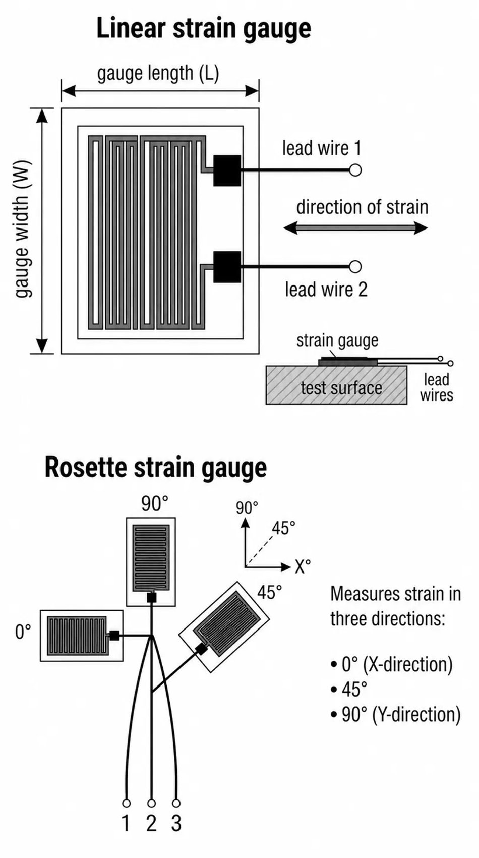
When the principal strain direction is not known ahead of time, a single linear gauge cannot resolve the full strain state at that point, since strain is a tensor quantity requiring multiple independent measurements to characterize fully at a given surface location. A rosette solves this by combining two or three individual grids on a single carrier, oriented at fixed, known angles relative to one another, most commonly a rectangular rosette at 0, 45, and 90 degrees, or a delta rosette at 0, 60, and 120 degrees. Reading all grids simultaneously provides enough independent strain values to mathematically solve for the two principal strains and the angle at which they occur, even when that orientation wasn't known before the gauge was installed.
This added information comes with a genuine construction tradeoff. Stacking multiple grid layers on top of one another, as opposed to arranging them side by side in a single plane, reduces the assembly's ability to dissipate self-generated heat, since each layer partially insulates the ones beneath it from the surrounding air or bonded surface.
Recommended Reading: Building a Remote Controlled Robotic Hand with Strain Gauges
Selecting a Strain Gauge: Key Parameters
Choosing a strain gauge isn't one decision; it's a stack of smaller ones, and manufacturers encode that entire stack into the part number itself. In the Micro-Measurements designation CEA-06-250UWA-350, every block is a separate choice someone made: gauge series, temperature compensation, length and pattern, resistance. Understanding what each piece means is really understanding how to select a gauge. 1
Gauge Length
The first real decision is how big the sensing grid should be, and the reason isn't really about the gauge, it's about what you're measuring. Strain isn't always uniform across a surface. Near a notch, hole, or fillet, it can spike sharply over a very small area, while on something like concrete or a fiber composite, strain varies depending on whether you happen to be sitting on a hard aggregate particle or the softer matrix around it.1
A strain gauge doesn't measure a single point, it measures an average across the length of its grid. 1 That's the whole reason gauge length matters. If we pick a gauge that is too long, a sharp local strain spike gets smeared out and underestimated, and the gauge also dissipates less heat and becomes harder to install in tight spaces. If we pick a gauge that is too short on an inhomogeneous material, we risk landing entirely on one particle or fiber, giving a reading that isn't representative of the material at all. 1 As a general reference point, published gauge performance data is usually built around gauges of 3mm or larger. 1
Gauge Resistance: 120 Ohm vs 350 Ohm
Standard resistances are 120 ohm and 350 ohm, with 1 kiloohm and 5 kiloohm available. The 120 ohm value dominated historically for instrumentation stability reasons, but modern instrumentation has removed that constraint.
Where you have a choice, prefer higher resistance. It reduces the heat generation rate significantly and decreases lead wire effects, including gauge factor desensitization caused by lead resistance in series with the active gauge. 1,10
The self-heating difference is easy to quantify. In a balanced bridge at 5 V excitation, each arm sees 2.5 V:
120 ohm gauge: P = 2.5² / 120 = 52 mW
350 ohm gauge: P = 2.5² / 350 = 18 mW
That gap matters most on materials that don't conduct heat away well, plastics especially, where self-heating shows up as a slow, false drift in your zero reading rather than as actual strain.
Self-Temperature-Compensation (STC) Number
The STC number matches the gauge's thermal output to the thermal expansion coefficient of the test material. Selecting the correct one removes most of the apparent strain error before you do anything else.
STC code | Material | Expansion coefficient (10⁻⁶/K) |
1 | Ferritic steel | 10.8 4 |
3 | Aluminum | 23 4 |
5 | Austenitic steel | 16 |
6 | Silica / composite | 0.5 |
7 | Titanium / gray cast iron | 9.0 |
8 | Plastic | 65 |
9 | Molybdenum | 5.4 |
Values consistent with HBK's published compensation examples. The mismatch case is worth being explicit about: a gauge compensated for ferritic steel, bonded instead to aluminum, will produce a large false reading as ambient temperature drifts, not because anything is broken, but because the gauge was tuned for a completely different expansion rate than the part it's sitting on. 4
One more spec worth knowing here: resistance tolerance on standard gauges usually runs about ±0.5% for single-element gauges and ±0.6% for multi-grid gauges. Option LE, an added encapsulation feature, doubles that tolerance, which becomes relevant if you're building a matched bridge and need every arm close to identical. 1
Gauge Pattern
Whether you need a single-axis linear gauge or a multi-grid rosette is also part of this same selection stack; see Gauge Patterns above.
Beyond the Gauge Itself
A few more decisions round out a full installation, though they extend past the gauge as a product and into how it's installed and protected. Options like pre attached lead wires or extra encapsulation layers trade off installation speed against durability. The bonding adhesive you choose needs to match your expected temperature range and the strain levels you're measuring, since the adhesive can fail before the gauge does. And environmental protection, coatings against moisture, oil, or corrosive exposure, determines how long an installation survives in the field versus a controlled lab setting. 1 These aren't things this article covers in depth, but they're worth knowing exist as real decisions once you move from choosing a gauge to actually installing one.
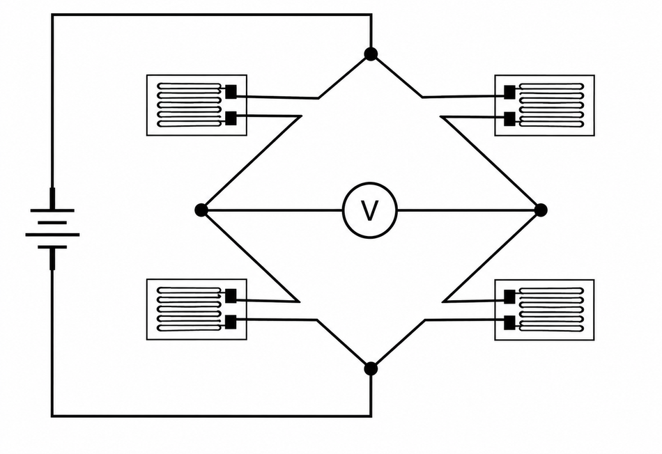
Wheatstone Bridge Circuits
A strain gauge's resistance change is too small to read directly. A few tenths of an ohm on a 350 ohm gauge falls below what an ohmmeter can distinguish from lead resistance and thermal drift. The Wheatstone bridge solves this.
A Wheatstone bridge is a passive resistive network that converts a small resistance change into a proportional voltage difference, which instrumentation can then read and, if needed, amplify further downstream. Four resistances form the arms of the bridge. A small excitation voltage Vs is applied across one diagonal, and the output voltage Vo is read across the other.
The bridge is set up so that with no strain applied, all four arms are matched and the output sits at zero. 3 When the gauge's resistance shifts under strain, that balance is disturbed, and the imbalance itself is what appears as the output voltage.
For strain work, the general relation reduces to:
Vo/Vs = (k × ε × B) / 4
where B is the bridge factor set by how many gauges are active and how they are arranged.
Quarter-Bridge
One active gauge, three fixed completion resistors. B = 1.
It is the easiest to install and the most common in experimental stress analysis. The drawbacks are real: normal and bending strain are superimposed, and temperature effects are not automatically compensated.
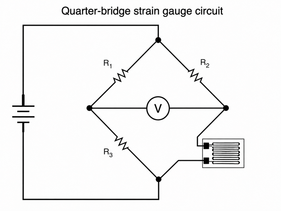
Adding an external dummy gauge, bonded to an unstrained piece of the same material at the same temperature, gives good temperature compensation while keeping a single active gauge. 4
Half-Bridge
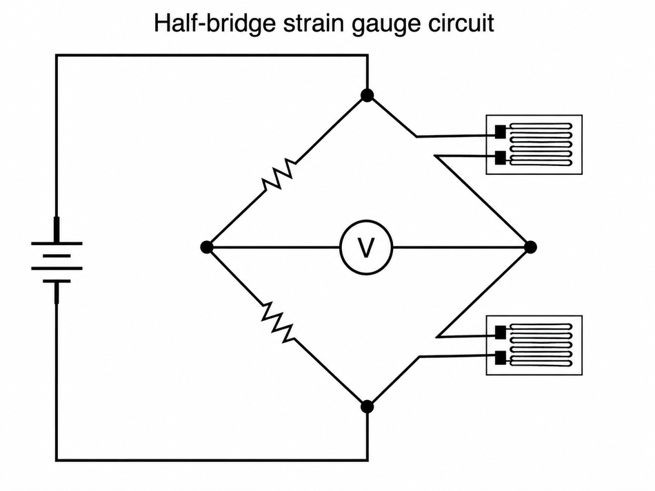
Two active gauges. B depends on the arrangement.
Two gauges on opposite faces of a bending beam give B = 2 and, more usefully, separate bending from axial strain while cancelling temperature effects. A Poisson half-bridge places the second gauge at 90 degrees to the first 3, giving good temperature compensation on isotropic material.4
Full Bridge
Four active gauges. Bridge factor up to 4 on a bending beam.
Full bridges give the largest output voltage and the best rejection of temperature and unwanted load components. Transducers such as load cells and torque sensors should always use a full bridge with active gauges in all four arms, because they face tighter accuracy requirements than experimental stress analysis.
Worked Example: Sizing a Quarter-Bridge Measurement
Take a steel tension member instrumented with one 350 ohm gauge, k = 2.05, at 5 V excitation, loaded to 500 micro strain.
Bridge output ratio: Vo/Vs = (2.05 × 500 × 10⁻⁶ × 1) / 4 = 0.256 mV/V
Output voltage: Vo = 5 V × 0.256 mV/V = 1.28 mV
Stress: σ = E × ε = 210 GPa × 500 × 10⁻⁶ = 105 MPa
A 1.28 mV full-scale signal is a large part of why strain gauge instrumentation depends on precision amplification and careful shielding. Thermoelectric voltages, typically a few to tens of microvolts, form at every dissimilar-metal junction in the measurement loop, and against a signal this small, even that microvolt-level offset represents a real, measurable percentage error.
Move the same measurement to a bending beam full bridge and the output rises to 5.12 mV, a factor of four improvement for three extra gauges.
Recommended Reading: Wheatstone Bridge: Principles, Configurations, and Signal Conditioning for Precise Measurements
Temperature Effects and Temperature Compensation
Temperature is one of the largest error sources in strain measurement, and it enters through several independent paths.4
Apparent Strain
Materials expand as they warm. Steel expands roughly 11 ppm/K, meaning 11 micro strain per degree Celsius with no load applied at all. Against a 500 micro strain working signal, a 10 °C swing produces a 110 micro strain error, over 20%.4
This unloaded thermal reading is called apparent strain, and it is why STC selection matters so much.4
Compensation Methods
Self-compensated gauges. Match the STC number to the specimen material. This removes the bulk of apparent strain. Manufacturers provide thermal output curves or polynomial coefficients; residual errors are typically on the order of several µε/°C and are nonlinear with temperature. 4,1
Bridge arrangement. In a half or full bridge, adjacent arms enter the output with opposite signs. On a bending beam, load produces tension on one face and compression on the other (opposite signs, signals add), while a temperature change affects both gauges identically (same sign, signals cancel).4
Three-wire hookup. In a two-wire circuit, cable resistance adds directly to gauge resistance, causing zero drift and desensitizing the gauge factor. A three-wire circuit places the two lead resistances in adjacent bridge arms so their temperature-dependent changes cancel. 9
Computational compensation. Measure temperature alongside strain and correct numerically. This handles the residual from self-compensation and the temperature coefficient of the gauge factor, which at roughly 0.01%/K is small enough to ignore in most work.4
Adhesive limits matter as much as gauge limits. If the adhesive softens, strain stops transferring faithfully. Typical adhesive ceilings vary by chemistry, fast-cure cyanoacrylates generally suit lower-temperature work, while specialized epoxies extend usable range considerably further, and foil gauge carriers and complete gauge constructions are generally limited to roughly 300–400°C, depending on materials and adhesive. 1
Installation and Bonding
Installation quality determines measurement quality. Good results depend heavily on surface preparation, the adhesive, protective coating, and the skill of the installer.14
Degrease the area with a solvent to remove oils.
Abrade the surface to a uniform matte finish, typically with progressively finer abrasive paper, to give the adhesive a mechanical key.
Where specified by the adhesive system, condition and neutralize with the manufacturer's conditioner and neutralizer to prepare the surface.
Align the gauge to the intended strain axis using the printed alignment marks and layout lines. Misalignment of a few degrees introduces a measurable cosine‑type error in the measured strain.
Bond with the adhesive selected for the temperature range, applying the specified clamping pressure and cure schedule.
Wire and protect. Solder leads without excess solder on the tabs, remove all flux residue, then apply protective coating.
Two details bite regularly. Excess solder on the gauge tabs is a known cause of variable fatigue life. And, for many encapsulated gauges, keeping strain levels at the terminal location below about ±1000 micro strain helps preserve fatigue life; high‑endurance series may allow higher strains, but local strain relief is still recommended.
Applications
Strain gauges appear anywhere force, pressure, torque, or structural response needs quantifying:
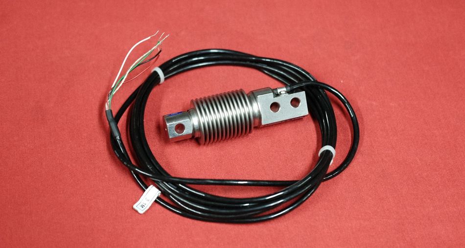
Load Cells
Bonded gauges in a full bridge on a machined spring element form the basis of nearly all electronic weighing. From industrial scales to a dump truck's payload, this same principle scales from milligrams to tons. It's likely the highest-volume application of strain gauges in existence for force measurements, since virtually every digital scale relies on one.
Pressure Transducers and Pressure Sensors
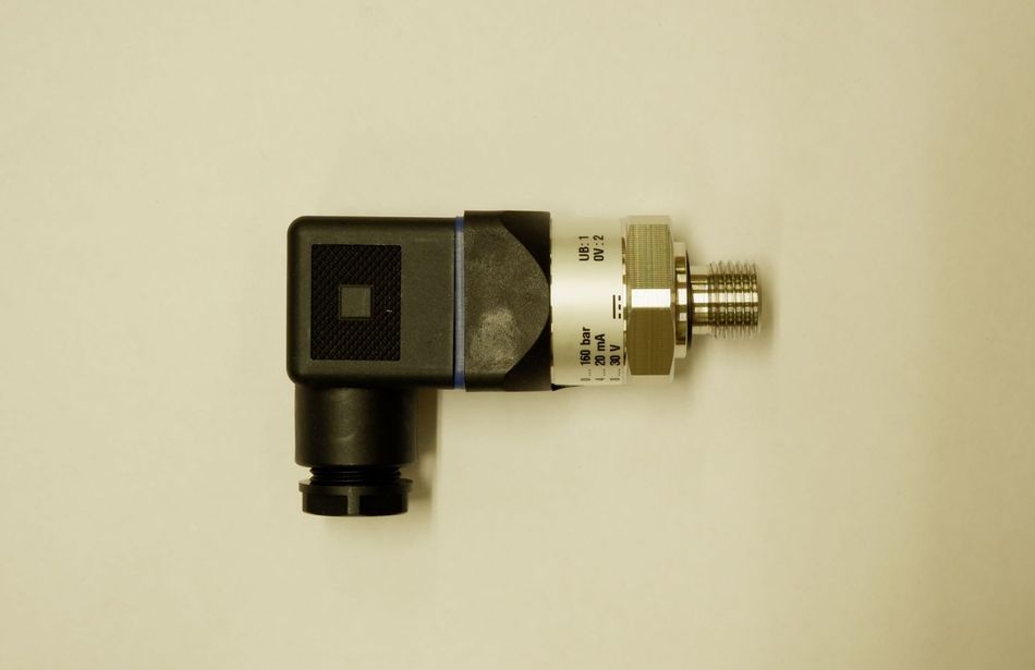
Gauges bonded to a diaphragm convert its tiny deflection under pressure into a proportional electrical signal. Semiconductor gauges dominate the miniature end of this market, prized for their much higher sensitivity in a small package.9 This is the working principle behind everything from industrial process sensors to blood pressure monitors.
Torque Sensors
Gauges mounted at 45 degrees to the shaft axis sit directly along the principal shear strain direction created by torque. 9 This orientation is standard across shaft power measurement, drivetrains, and torque wrenches. A second gauge at 135 degrees, forming a V-shaped pair, is common for improved sensitivity and temperature cancellation.
Experimental Stress Analysis
Gauges bonded to physical prototypes provide real measured strain data to validate finite element models before a design is finalized. 9 This closes the loop between simulation and reality, catching stress concentrations a model might miss. It remains one of the most direct ways to confirm a design actually behaves as predicted.
Structural Testing and Civil Engineering
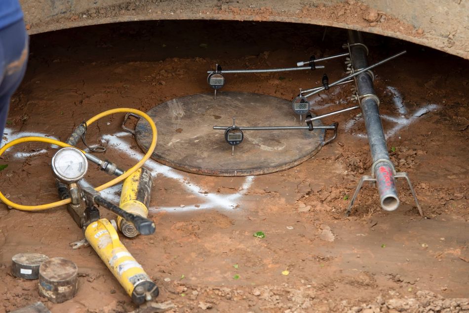
Gauges embedded in or bonded to bridges, cranes, pressure vessels, and building elements track fatigue accumulation and overload conditions over time. Many are installed permanently, allowing monitoring that continues for months or years after initial testing. This turns strain measurement from a one-time validation step into ongoing structural health monitoring.
Aerospace and Automotive
Flight-load surveys use strain gauges across an airframe to confirm it behaves within predicted limits under real flight conditions. In automotive work, the same principle measures chassis and suspension loads, and drives durability testing under repeated dynamic strain. Both industries depend on this data to validate fatigue life before a design reaches production.
Common Mistakes and Troubleshooting
Symptom | Likely cause | Fix |
Reading drifts with no load | Apparent strain from temperature, or self-heating | Correct STC number, lower excitation, higher resistance gauge |
Output much lower than predicted | Lead resistance reducing bridge sensitivity | Three-wire hookup, higher resistance gauge, shorter leads |
Erratic or noisy signal | Poor bond, moisture ingress, unshielded leads | Reinstall, apply protective coating, shield and ground properly |
Zero shifts after load cycling | Adhesive creep, bond degradation, or gauge/lead damage | Check adhesive temperature limit, redo surface preparation |
Strain near a stress concentration depends on gauge length | A long gauge averages across the gradient and may not capture the true peak | Shorter gauge length |
Signal decays under sustained load | Adhesive creep | Higher-temperature adhesive, verify cure schedule |
It's standard, well-established practice in the field that individual bonded strain gauges are not calibrated one by one. Because most of a gauge's performance characteristics can only be verified through destructive testing, manufacturers instead test sample gauges from a production lot and apply those results statistically to the rest of the batch. This limitation is significant enough that it's formally codified in the governing US standard for gauge performance testing.5 If your application requires a directly calibrated, traceable sensor, use a calibrated transducer, a load cell or pressure sensor, that incorporates bonded gauges, rather than relying on a bare gauge alone.
Standards
The governing standard for gauge performance characteristics in the United States is ASTM E251-20a, Standard Test Methods for Performance Characteristics of Metallic Bonded Resistance Strain Gages, currently active and last updated in August 2020. 5
It defines uniform test methods for five performance parameters: resistance at a reference temperature, gauge factor at a reference temperature, temperature coefficient of gauge factor, transverse sensitivity, and thermal output. When comparing datasheets across manufacturers, confirm the figures are reported per E251; otherwise you may be comparing values measured differently.
Conclusion
A strain gauge is a simple device wrapped in demanding practice. The physics reduces to one constant, the gauge factor, but extracting a trustworthy number means controlling everything around it.
Select the gauge length for your strain gradient, prefer 350 ohm over 120 ohm where you can, match the STC number to your material, and use the highest bridge factor your budget allows. Then spend real effort on surface preparation, because no amount of instrumentation quality recovers a bad bond.
Get those choices right and a bonded foil gauge will resolve strain to a few microstrains on production hardware, which remains an extraordinary capability for a sensor that costs a few dollars to a few tens of dollars.
Frequently Asked Questions
What is a strain gauge used for?
A strain gauge is used to measure mechanical strain on a surface, from which stress is then calculated using Hooke's law. It also serves as the core sensing element inside load cells, pressure transducers, and torque sensors, converting mechanical deformation into an electrical signal in each case. 2,9
What is the gauge factor of a strain gauge?
The gauge factor is the ratio of a strain gauge's fractional resistance change to the strain that caused it. Metallic foil gauges typically have a gauge factor between 2 and 5, while semiconductor gauges can reach 100 or higher due to the piezo resistive effect. 7
Why do strain gauges use a Wheatstone bridge?
Because a strain gauge's resistance change is typically only around 0.1%, far too small to read directly with an ohmmeter against lead resistance and drift. The Wheatstone bridge converts that tiny relative change into a differential output voltage that downstream instrumentation can amplify, and depending on how the arms are arranged, it can also cancel out temperature effects. 3
What is the difference between 120 ohm and 350 ohm strain gauges?
Both are standard. A 350 ohm gauge dissipates roughly a third of the self-heating power at the same excitation and is less affected by lead resistance. 120 ohm remains common for legacy instrumentation compatibility.9,10
Who invented the strain gauge?
The bonded resistance strain gauge was independently invented by two people in 1938: Edward E. Simmons, a research assistant at Caltech, and Arthur C. Ruge, a professor at MIT. 12,13
Is it "strain gauge" or "strain gage"?
Both are correct for the same device. "Gauge" is the international spelling; "gage" is conventional in United States industry and in ASTM standards.1,2,5
How accurate is a strain gauge?
With correct STC selection, good installation, and temperature compensation, a few micro strains are achievable. Individual gauges cannot be calibrated, so accuracy comes from lot statistics plus installation quality.5
What is apparent strain?
Apparent strain is the strain reading a gauge shows purely from thermal expansion of the specimen, with no mechanical load applied at all. Steel expands roughly 11 micro strain per degree Celsius, which makes apparent strain one of the largest error sources in strain measurement if it isn't compensated for. 4
Can strain gauges measure dynamic strain?
Yes. Foil gauges have excellent frequency response. Isoelastic alloy gauges are made specifically for dynamic strain, though their high thermal output rules them out for static work.1
References
[1] Micro-Measurements, "Strain Gage Sensor Reference Guide: Considerations for Parameter Selection," Vishay Precision Group. [Online]. Available: https://docs.micro-measurements.com/?id=8690
[2] Micro-Measurements, "What is a Strain Gage?" Vishay Precision Group. [Online]. Available: https://micro-measurements.com/what-is-a-strain-gage
[3] HBK, "The Wheatstone Bridge Circuit Explained," Hottinger Brüel & Kjær. [Online]. Available: https://www.hbkworld.com/en/knowledge/resource-center/articles/wheatstone-bridge-circuit
[4] HBK, "Strain Gauges: How to Prevent Temperature Effects on Your Measurement," Hottinger Brüel & Kjær. [Online]. Available: https://www.hbkworld.com/en/knowledge/resource-center/articles/article-temperature-compensation-of-strain-gauges1
[5] ASTM International, "Standard Test Methods for Performance Characteristics of Metallic Bonded Resistance Strain Gages," ASTM E251-20a, West Conshohocken, PA, 2020. [Online]. Available: https://store.astm.org/e0251-20a.html
[6] Wikipedia contributors, "Strain gauge," Wikipedia, The Free Encyclopedia. [Online]. Available: https://en.wikipedia.org/wiki/Strain_gauge
[7] Wikipedia contributors, "Gauge factor," Wikipedia, The Free Encyclopedia. [Online]. Available: https://en.wikipedia.org/wiki/Gauge_factor
[8] H. Li et al., "A Supersensitive, Multidimensional Flexible Strain Gauge Sensor Based on Ag/PDMS for Human Activities Monitoring," Scientific Reports, vol. 10, p. 4639, 2020. [Online]. Available: https://pmc.ncbi.nlm.nih.gov/articles/PMC7070104/
[9] DwyerOmega, "Strain Gauge Technical Resources," Omega Engineering. [Online]. Available: https://www.dwyeromega.com
[10] National Instruments, "Measuring Strain with Strain Gages," NI. [Online]. Available: https://www.ni.com/en/shop/data-acquisition/sensor-fundamentals/measuring-strain-with-strain-gages.html
[11] HBK, "Hooke's Law Explained," Hottinger Brüel & Kjær. [Online]. Available: https://www.hbkworld.com/en/knowledge/resource-center/articles/strain-measurement-basics/strain-gauge-fundamentals/experimental-stress-analysis-using-strain-gauges/hookes-law
[12] MIT Museum, "Invention of the Strain Gauge, Arthur Ruge, 1938," MIT 150 Exhibition. [Online]. Available: http://museum.mit.edu/150/82
[13] Wikipedia contributors, "Arthur Claude Ruge," Wikipedia, The Free Encyclopedia. [Online]. Available: https://en.wikipedia.org/wiki/Arthur_Claude_Ruge
[14] Vishay Precision Group, "Strain Gage Installations with M-Bond 200 Adhesive," Instruction Bulletin B-127-14, Micro-Measurements. [Online]. Available: https://intertechnology.com/Vishay/pdfs/Instruction_Bulletins/B-127-14.pdf
in this article
1. Key Takeaways2. Introduction3. What Is a Strain Gauge?4. Construction of a Strain Gauge5. How a Strain Gauge Works: The Gauge Factor6. Selecting a Strain Gauge: Key Parameters7. Wheatstone Bridge Circuits8. Temperature Effects and Temperature Compensation9. Installation and Bonding10. Applications11. Common Mistakes and Troubleshooting12. Standards13. Conclusion14. Frequently Asked Questions15. References