What Is a Fuel Cell? Theory, Components, Types, and Applications
This article explains what is a fuel cell by reviewing its components, classifications, performance, limitations, and real world uses.

09 Aug, 2026. 16 minutes read
Key Takeaways
Direct Energy Conversion – Fuel cells convert the chemical energy of hydrogen and other fuels directly into electricity with typical electrical efficiencies around 40–60% and a theoretical reversible potential of 1.229 V for a hydrogen‑air cell.
Stack Architecture and Components – The fuel cell stack comprises a membrane electrode assembly with a proton‑conductive membrane, platinum catalysts, gas diffusion layers, and bipolar plates that manage fuel distribution and current collection.
Chemistries and Temperature Ranges – Different fuel cell types include polymer electrolyte membrane (PEM), alkaline, phosphoric acid, molten carbonate, solid oxide, direct methanol, and microbial fuel cells; they operate across temperatures from <100°C to ~1,000°C and deliver efficiencies up to about 60%.
Polarization Losses – Real‑world performance is limited by activation, ohmic, and concentration losses; activation losses alone reduce open‑circuit voltage by about 0.1–0.2 V.
Hydrogen Production Landscape – Hydrogen production remains dominated by fossil fuels, with around 47% from natural gas and only about 4% from electrolysis; electrolyzer deployment is expanding, with China representing roughly 60% of global manufacturing capacity.
Introduction
Modern societies seek energy systems that deliver high efficiency with minimal environmental impact. Heat engines, such as internal combustion engines, typically convert only 30–40% of the fuel energy into useful work, losing the rest as waste heat. Batteries, by contrast, can achieve 80–90% round‑trip efficiency but store finite energy and require lengthy charging. Fuel cells occupy a middle ground: they produce electricity through electrochemical reactions without combustion, providing higher efficiency than engines and continuous operation when supplied with fuel. Understanding what is a fuel cell requires examining its theory, including oxidation at the anode, reduction at the cathode, and ion transport through an electrolyte.
Unlike batteries, fuel cells do not store a fixed quantity of energy; they continue generating power as long as fuel and oxidant are supplied. This article explains what is a fuel cell by reviewing its components, classifications, performance, and limitations. It compares proton-exchange membrane, solid oxide, alkaline, phosphoric acid, and molten carbonate technologies. By addressing what is a fuel cell from theoretical and application perspectives, the discussion provides a foundation for evaluating its role in modern transport, industry, backup power, and distributed generation.
What is a Fuel Cell?
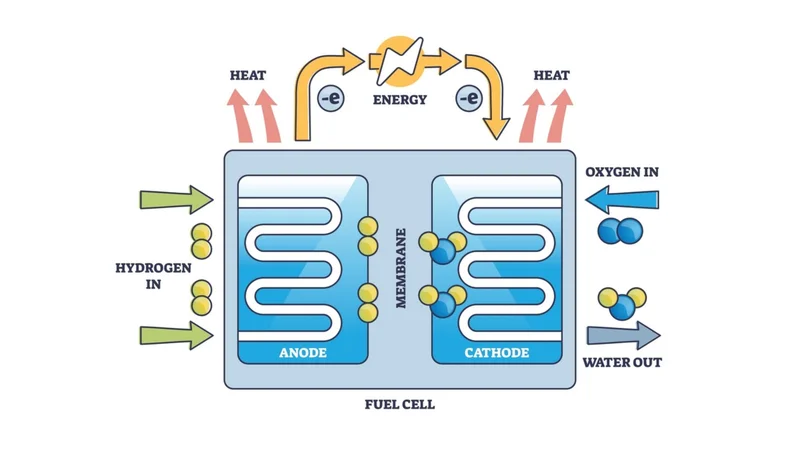
The fuel cell is an electrochemical device that converts the chemical energy of a fuel and oxidant directly into electricity, heat, and water without combustion. In its simplest form, the cell consists of two electrodes separated by an electrolyte. Hydrogen gas supplied to the anode is catalytically split into protons and electrons; the protons migrate through the electrolyte while electrons flow through an external circuit, delivering electrical power to a load. The electrons at the cathode recombine with protons and oxygen to form water.
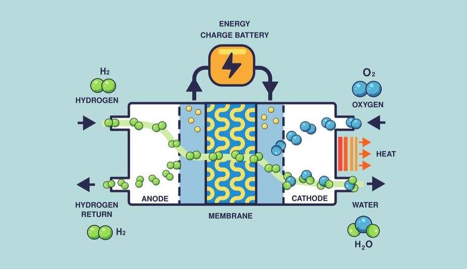
Because there is no intermediary thermal process, the conversion is not bound by the Carnot limit, and theoretical efficiencies can approach 100% under reversible conditions.
Definition and Contrast with Batteries and Engines
Unlike batteries, which store chemical energy and discharge it until depleted, fuel cells are open systems that continuously convert externally supplied fuel and oxidant. Their power output persists as long as fuel flows. Internal combustion engines also accept continuous fuel but rely on thermodynamic cycles limited by heat‑engine efficiency and produce pollutant emissions. Fuel cells offer higher theoretical efficiency and cleaner exhaust, though they require pure fuels and complex balance‑of‑plant components to manage reactants, heat, and water.
Reaction and Theoretical Voltage
For the hydrogen–air fuel cell, the overall reaction is:
H₂ + ½ O₂ → H₂O,
with a Gibbs free‑energy change ΔG° ≈ –229 kJ mol⁻¹. This relates to the reversible cell potential via ΔG° = –nFE (rev), where n = 2 electrons per molecule of hydrogen and F = 96,500 C mol⁻¹ is Faraday's constant. Substitution yields a reversible potential E (rev) of 1.229 V at standard conditions. The corresponding thermoneutral potential, based on the enthalpy change, is 1.48 V; this is the voltage at which the reaction's heat release is exactly balanced by the heat consumption in the cell.
In practice, the cell voltage is lower due to irreversible losses. The activation overpotentials at the electrodes reduce the open‑circuit voltage by about 0.1–0.2 V. Once the current increases, resistive (ohmic) drops across the membrane, electrodes and current collectors further decrease the voltage. The mass‑transport limitations at high current densities cause concentration losses when reactants cannot be supplied or products removed fast enough.[3] The resulting voltage–current relationship is summarised by the cell's polarisation curve.
How a Fuel Cell Works?
The heart of a fuel cell is the membrane electrode assembly (MEA), which comprises a thin polymer electrolyte membrane sandwiched between catalyst layers and gas diffusion layers. Understanding the electrochemical processes and transport phenomena within this assembly is essential for designing efficient and durable fuel cells.
Electrochemical Half Reactions
At the anode, hydrogen molecules adsorb on catalyst sites and dissociate:
H₂ → 2H⁺ + 2e⁻ (Anode)
The protons migrate through the electrolyte to the cathode, while the electrons travel through the external circuit, generating useful electrical energy. At the cathode, oxygen reduction occurs:
½ O₂ + 2H⁺ + 2e⁻ → H₂O (Cathode)
These half reactions illustrate that the electrolyte must conduct ions (protons in PEM cells) but block electrons to prevent internal short circuits. The polymer electrolyte membranes are perfluorosulfonic acid films only 10–20 µm thick that conduct protons while acting as electronic insulators. The catalyst layers on both sides of the membrane typically use platinum-on-carbon catalysts to promote hydrogen oxidation and oxygen reduction.[1] The gas diffusion layers made of carbon paper impregnated with polytetrafluoroethylene (PTFE) evenly distribute reactants and remove water.
Transport and Polarisation Losses
The flow of protons and electrons is accompanied by the transport of mass and heat. The activation overpotentials arise because finite reaction rates require additional voltage to drive the electrochemical kinetics; they are highest at low current densities and can account for 0.1–0.2 V of voltage drop.[3] Ohmic losses originate from the ionic resistance of the membrane, the electronic resistance of the electrodes and bipolar plates, and contact resistances. Concentration losses become significant at high electric currents when oxygen or hydrogen cannot reach reaction sites or when product water floods the electrodes.
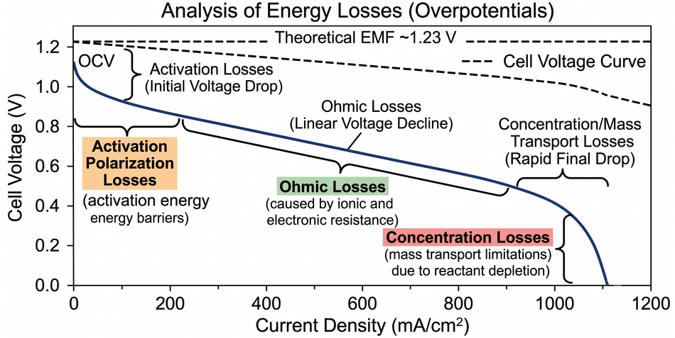
The typical polarisation curve rises from zero current at the open‑circuit voltage, slopes downward as activation and ohmic losses accumulate, and steeply drops as concentration losses dominate. Designers minimize these losses by selecting high‑activity catalysts, low‑resistance membranes, optimized gas‑flow channels and water‑management strategies.
Water and Heat Management
In PEM fuel cells, the protonic conductivity of the membrane depends on its hydration state. Insufficient water dries out the membrane, increasing ionic resistance, while excess water floods the cathode, blocking gas transport.
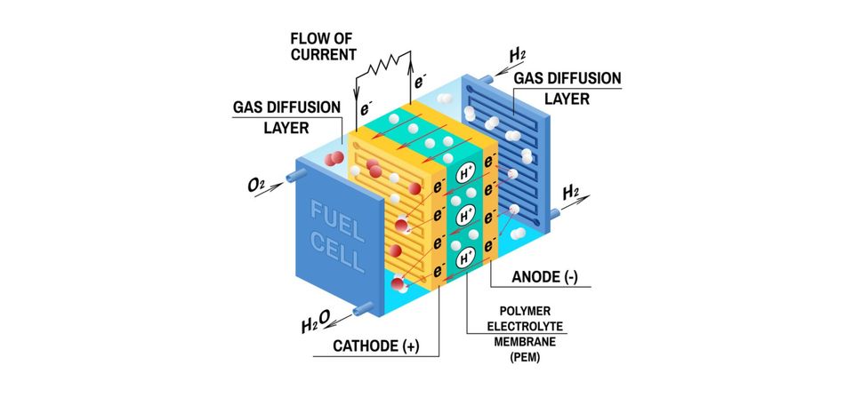
The gas diffusion layers and microstructured flow fields manage the delicate balance: PTFE treatment prevents water accumulation, and channels incorporate serpentine or parallel patterns to enhance humidification and drainage. Heat generated by irreversible losses must also be removed to maintain optimal operating temperature (typically 60–80 °C for PEM cells). Bipolar plates sometimes integrate cooling channels to distribute coolant across the stack.[1]
Recommended Reading: Diode, Anode, Cathode: Unlocking the Power of Semiconductor Junctions
Components of a Fuel Cell Stack
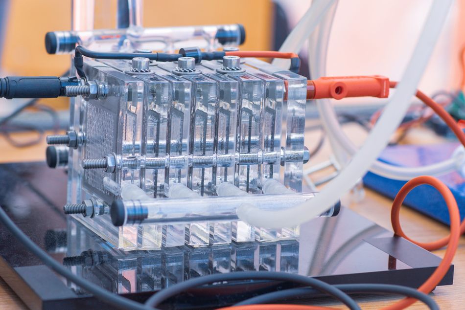
The fuel cell stack comprises multiple cells connected in series to achieve the desired voltage and power. Each cell contains several key components:
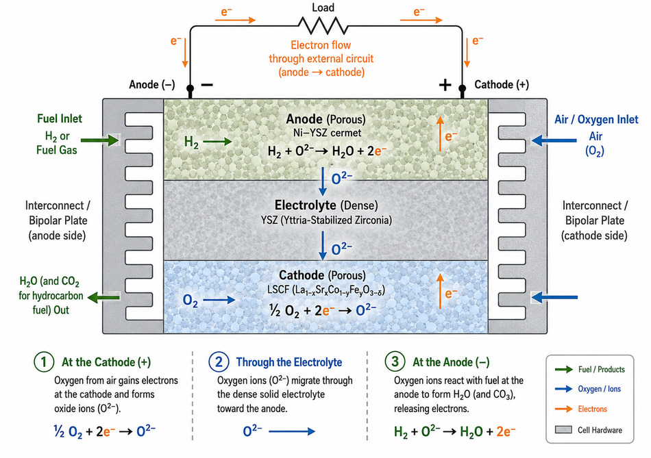
Electrolyte Membrane: In PEM fuel cells, this is a perfluorosulfonic acid membrane only tens of micrometers thick that conducts protons but blocks electrons. Alkaline and phosphoric acid fuel cells use aqueous solutions or polymer membranes that conduct hydroxide or phosphoric acid ions, while molten carbonate and solid oxide fuel cells employ high‑temperature ionic conductors such as molten carbonate salts or yttria‑stabilised zirconia.
Catalyst Layers: Thin layers of platinum on carbon or other catalysts facilitate the hydrogen oxidation and oxygen reduction reactions. High‑temperature systems may use nickel or perovskite materials. Platinum‑group metals remain a major cost driver; research seeks non‑noble catalysts.
Gas Diffusion Layers (GDLs): Porous carbon paper or cloth impregnated with PTFE evenly distributes gas over the catalyst and removes product water. In high‑temperature cells, porous ceramics or metal meshes serve the same purpose.
Bipolar Plates: Graphite, carbon‑polymer composites or coated metals form plates that separate cells, provide channels for fuel and oxidant distribution, collect current and maintain structural integrity. Some plates incorporate cooling channels to remove heat. Gaskets and seals ensure gas‑tight assembly.
Balance of Plant: Pumps, compressors, humidifiers, heat exchangers, control electronics, and power-conditioning equipment support the stack. For fuel cell vehicles, this balance-of-plant component can comprise more than half of the system cost.
Advances in materials and manufacturing, such as low‑cost coated metals for bipolar plates and roll‑to‑roll fabrication of MEAs, are critical to reducing fuel cell costs and improving durability.
Types of Fuel Cells
Fuel cells are classified by their electrolyte and operating temperature. Each type has distinct characteristics, advantages, and challenges.
Polymer Electrolyte Membrane (PEM) Fuel Cells
PEM fuel cells, also called proton exchange membrane fuel cells, use solid polymer membranes such as perfluorosulfonic acid. They operate at temperatures below 120 °C, making them suitable for vehicles, backup power, and portable devices.[2] Their electrical efficiency on hydrogen is around 60%, and power densities can exceed 1 W cm⁻².
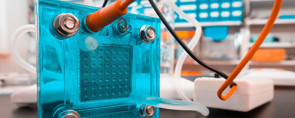
The advantages include low temperature, fast start‑up, high power density, and solid electrolyte. Challenges include the high cost of platinum catalysts and sensitivity to impurities such as carbon monoxide and sulfur. In this, water management is critical for membrane hydration.
High‑Temperature PEM: By doping polybenzimidazole membranes with phosphoric acid, high‑temperature PEM fuel cells operate at 150–200 °C and exhibit improved tolerance to carbon monoxide (up to ~3 %). They simplify balance‑of‑plant design and enable integration with reformed methanol or natural gas but often have lower power density.
Direct Methanol Fuel Cells (DMFC): These are a subset of PEM technology that oxidise liquid methanol directly. They operate at 50–130 °C, yield efficiencies around 40%, and are used in portable electronics and small power systems. Methanol crossover through the membrane and low reaction rates remain challenges.
Alkaline Fuel Cells (AFC)
AFCs utilize aqueous potassium hydroxide or alkaline polymer membranes to conduct hydroxide ions. Operating at temperatures below 100 °C with efficiencies around 60%, they have powered space missions and military systems.[2] The electrolyte is inexpensive, and the catalysts can be non‑noble, but AFCs are sensitive to carbon dioxide, which reacts with the electrolyte to form carbonates. Tight control of incoming air and fuel purity is required, which limits widespread commercial use.
Phosphoric Acid Fuel Cells (PAFC)
PAFCs employ concentrated phosphoric acid as the electrolyte, operating at 150–200 °C.[2] Their efficiency is about 40%, and typical stack sizes range from 5–400 kW. PAFCs are robust against carbon monoxide and fuel impurities and are well suited for distributed generation and combined heat and power systems because their waste heat is available at useful temperatures. Challenges include sluggish oxygen reduction kinetics, requiring significant platinum loading, and longer start‑up times.
Molten Carbonate Fuel Cells (MCFC)
MCFCs use molten carbonate salts, such as lithium–potassium carbonate, as the electrolyte. Operating at 600–700 °C, they achieve efficiencies around 50% and power outputs from 300 kW to several megawatts.[2] High operating temperatures enable the use of non‑noble nickel catalysts and facilitate the internal reforming of hydrocarbons, thereby enabling fuel flexibility. MCFCs are attractive for electric utilities and industrial combined heat and power because they produce high‑temperature exhaust for cogeneration. However, the molten electrolyte corrodes materials and requires robust corrosion‑resistant components; start‑up times are long, and power density is relatively low.
Solid Oxide Fuel Cells (SOFC)
SOFCs employ solid ceramic electrolytes such as yttria‑stabilised zirconia that conduct oxygen ions at 500–1 000 °C.[2] Operating at the highest temperature among fuel cells, SOFCs reach electrical efficiencies near 60% and can exceed 85% in combined heat and power or hybrid cycles. Their high temperature enables the internal reforming of natural gas and other hydrocarbons and supports the use of abundant non‑noble electrodes. Applications range from 1 kW auxiliary power units to 2 MW distributed generation. Challenges include long start‑up times, material degradation due to thermal stresses and redox cycling, and the need for high‑temperature sealants.
Microbial Fuel Cells (MFC)
Microbial fuel cells utilize the metabolic activities of bacteria to oxidize organic matter in wastewater and generate electricity. They operate at ambient temperatures and achieve power densities in the range of tens to hundreds of milliwatts per square meter, with some designs reaching 5 Wm⁻². MFCs simultaneously treat wastewater by removing 80–95% of chemical oxygen demand. Despite their modest power output, they offer an elegant synergy between waste remediation and energy recovery. Challenges include electrode fouling, scaling, and low efficiency.
Methanol Fuel Cells
High‑temperature PEM fuel cells can be combined with onboard methanol reformers to produce hydrogen. Vehicles using such systems can achieve ranges of ~1,000 km with quick refueling.[7] The high energy density, liquid storage, and established logistics of Methanol make it an attractive carrier, though reformers add complexity and carbon dioxide emissions.
Recommended Reading: Flow Cell Technology: Comprehensive Guide
Efficiency and Performance
Understanding efficiency requires examining thermodynamics, reaction kinetics, and system integration. In theory, the reversible voltage of a hydrogen–air fuel cell is 1.229 V, corresponding to 100% conversion of Gibbs free energy to electrical energy. In practice, the cell voltage at rated current is typically 0.6–0.8 V for PEM and 0.7–0.9 V for SOFCs.
The electrical efficiency for PEM and SOFC stacks ranges from 40–60%.[1] Combined heat and power systems recover waste heat, boosting overall efficiency above 80%.
Thermodynamic Efficiency Limits
The theoretical efficiency η(th) is the ratio of Gibbs free energy to enthalpy change:
η(th) = |ΔG| / |ΔH|
For hydrogen oxidation, ΔG°/ΔH° ≈ 229/286 ≈ 0.80 at 25 °C. Thus, even an ideal fuel cell converting all Gibbs free energy cannot exceed about 80% electrical efficiency. Real fuel cells operate below this limit due to polarisation losses and auxiliary power consumption. The Nernst equation accounts for reactant pressures and water activity; lower pressures or humidities reduce the open‑circuit voltage.
Polarisation and Resistive Losses
The activation losses arise from kinetic barriers to electron transfer. Pt‑based catalysts reduce these barriers, but alternative catalysts can introduce higher overpotentials. Ohmic losses are mitigated by thin, highly conductive membranes and by minimising contact resistances. Concentration losses are mitigated by optimised flow fields and gas-diffusion media.
Durability and Degradation
Fuel cell lifetimes depend on electrode, membrane and balance‑of‑plant durability. In automotive PEM fuel cells, targets exceed 8,000 hours of operation. Degradation mechanisms include catalyst sintering and dissolution, membrane chemical attack, carbon corrosion, and mechanical stress from hydration cycles. High‑temperature systems suffer from thermal cycling and component creep. The modern stacks incorporate stable catalyst supports, reinforced membranes, and carefully managed water and gas distribution to extend life.
Hydrogen Production and Storage
Fuel cell viability depends on abundant, affordable hydrogen or other fuels. Global hydrogen production is around 75 Mt of pure hydrogen and 45 Mt in mixed gases; approximately 47% is derived from natural gas, 27% from coal, 22% from oil, and only about 4% from electrolysis. Low‑carbon hydrogen production remains a tiny fraction of total demand.
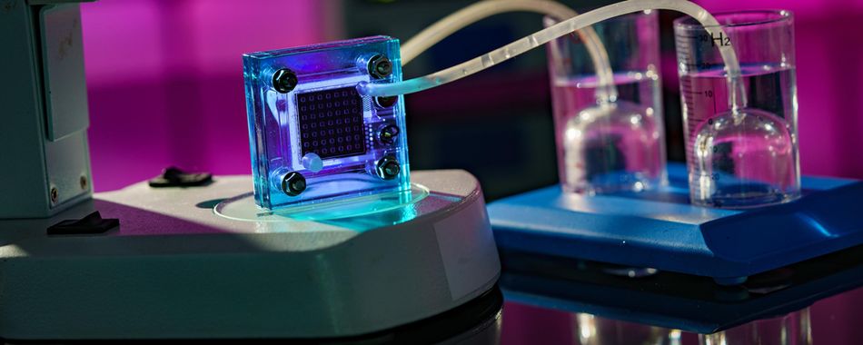
The International Energy Agency reported that low‑emissions hydrogen use increased in 2024 but still accounted for less than 1% of global hydrogen demand.[4]
Electrolysis and Renewable Hydrogen
Electrolysers split water into hydrogen and oxygen using electricity. Alkaline and PEM electrolysers dominate commercial deployment; solid oxide electrolysis is emerging. China holds nearly 60% of global electrolyser manufacturing capacity, enabling lower costs; renewable hydrogen costs are estimated to be 40–45% lower in China than in Europe or the United States.[4] Scaling electrolysis requires massive amounts of renewable electricity and water resources; coupling it with variable renewables can provide grid flexibility.
Reforming, Gasification and By‑Product Hydrogen
Steam methane reforming of natural gas is the dominant method of hydrogen production. It entails high CO₂ emissions unless paired with carbon capture. Coal gasification (dominant in China) emits even more CO₂. Oil refining produces by‑product hydrogen. Partial oxidation of heavy hydrocarbons and autothermal reforming combine exothermic and endothermic reactions. Methanol, ammonia and other liquid carriers can serve as hydrogen sources via reforming or decomposition; high‑temperature fuel cells are well suited for internal reforming.
Storage and Delivery
Hydrogen is stored as compressed gas (typically at 35 MPa for buses or 70 MPa for light vehicles), as cryogenic liquid at –253 °C, or within solid‑state materials such as metal hydrides and chemical hydrides. Compressed storage is commercially mature but provides lower volumetric energy density than liquid fuels. Liquid hydrogen offers higher density but incurs energy losses during liquefaction and boil‑off. For vehicle applications, type IV carbon‑fibre composite tanks deliver high strength‑to‑weight ratios.
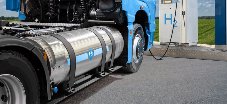
Hydrogen is delivered via pipelines, tube trailers, liquefied hydrogen ships or produced onsite by electrolysis or reforming. Hydrogen refuelling stations require compressors, storage tanks, dispensers and compliance with safety codes. In 2024, there were roughly 1,300 hydrogen stations worldwide, with China accounting for the majority and Europe and the United States trailing.[4]
Recommended Reading: Iron-based Hydrogen Storage
Applications
Fuel cells are employed across sectors ranging from transport to stationary power to special industries.
Their modular nature allows scaling from watts to megawatts.
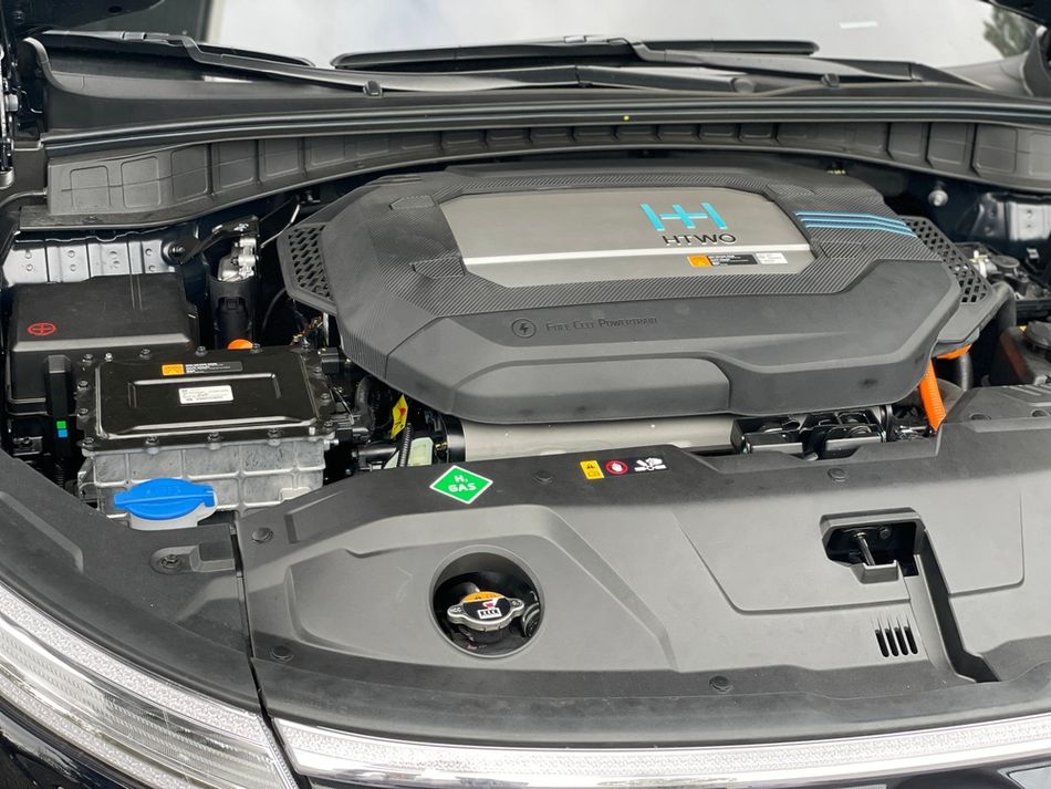
Transport: Fuel Cell Electric Vehicles
Fuel cell trains, trams and ferries are emerging as alternatives to diesel where overhead electrification is impractical. Aviation companies are exploring fuel cell auxiliary power units and hybrid powertrains for regional aircraft. Material handling equipment, such as forklifts, widely uses PEM fuel cells, benefiting from fast refuelling and consistent power in cold warehouses.
Stationary Power and Microgrids
Fuel cells provide reliable, low‑emission electricity for buildings, data centres and telecommunications. PAFCs and SOFCs supply combined heat and power to hospitals, hotels and universities. MCFCs and SOFCs produce distributed baseload power at tens of kilowatts to multi‑megawatts with high efficiency and useful heat. Microgrids in remote locations pair fuel cells with renewable generation and hydrogen storage to ensure resilience.
Portable and Emergency Power
Small PEM and DMFC units supply power to laptops, drones, surveillance equipment, and military devices when battery runtime is insufficient. Fuel cell backup systems replace diesel generators for telecommunications towers and data centres, offering high reliability and low emissions.
Industrial and Special Applications
Chemical plants use high‑temperature fuel cells for process heat and electricity, and integrated reformers convert process off‑gases to power. MFCs treat wastewater, producing electricity while reducing biochemical oxygen demand. High‑temperature fuel cells also enable carbon capture and sequestration by generating concentrated CO₂ streams from fuel.
Comparison with Batteries and Internal Combustion Engines
The table below compares key metrics across fuel cell electric vehicles (FCEV), battery electric vehicles (BEV), and internal combustion engine (ICE) vehicles.
| Metric | FCEV | BEV | ICE |
| Energy Conversion Efficiency | 40–60 % Electrical; Up to 85% with CHP | 80–90 % Battery Round‑Trip | 30–40% |
| Range (Light Vehicles) | 500–700 km Typical; Heavy‑Duty Trucks >1,000 km | 200–500 km Depending on Battery Size | 500–800 km with Diesel |
| Refuel / Charge Time | 3–5 min for 5–7 kg of Hydrogen; ~10 min for Buses | 30 min to Several Hours | ~5 min at Fuel Station |
| Energy Density (System) | 1–2 kWh kg⁻¹ for Compressed Hydrogen | 0.15–0.25 kWh kg⁻¹ for Lithium‑Ion | 11–13 kWh kg⁻¹ for Diesel Fuel |
| Infrastructure | ~1,300 Hydrogen Stations Worldwide | Hundreds of Thousands of Charging Stations | Established Refuelling Network |
| Emissions | Zero Tailpipe (Green H₂); Upstream Depends on H₂ Source | Zero Tailpipe; Upstream Depends on Grid Mix | CO₂, NOx, Particulates |
Fuel cells offer fast refuelling and long range, particularly beneficial for heavy‑duty transport and continuous‑operation applications. Batteries deliver higher efficiency and a mature charging network; they dominate passenger vehicle markets. ICE vehicles provide high energy density and low upfront costs but face tightening emission regulations.
Current Research and Future Outlook
The fuel cell field is dynamic, with ongoing research targeting performance, durability, cost, and sustainability.
Catalyst Development
The high cost and scarcity of platinum‑group metals drive research into alternative catalysts. A recent study reported an iron/nitrogen‑doped carbon catalyst with a curved microporous structure delivering record oxygen reduction activity: a peak power density of 0.75 W cm⁻² and 86% activity retention after 300 h.[6] Another project developed nickel catalysts coated with an atomically thin carbon layer that protects the nickel and enables high power output in alkaline fuel cells. Such catalysts could reduce cost and increase durability, making fuel cells more competitive.
High‑Temperature and Reversible Fuel Cells
High‑temperature PEM and solid oxide fuel cells enable internal reforming and tolerance to fuel impurities. Research on phosphoric acid‑doped polymer membranes focuses on improving conductivity and stability.[5] Unitised regenerative fuel cells integrate electrolysis and fuel cell modes into a single device, enabling round‑trip energy storage; they hold promise for renewable microgrids. Reversible solid oxide cells operate as electrolysers and fuel cells, offering high round‑trip efficiencies in the 60–70% range.
System Integration and Manufacturing
The advanced manufacturing techniques, including catalyst‑coated membranes, roll‑to‑roll processing and 3D printing of flow fields, reduce cost and improve uniformity. Smart control systems optimise water, heat and gas management, extending lifetime. Integration of fuel cells with batteries, supercapacitors and hydrogen storage in hybrid systems tailors response to transient loads.
Policy and Market Trends
The U.S. Infrastructure Investment and Jobs Act allocates $9.5 billion to hydrogen and fuel cell projects. Hydrogen Shot by DOE aims to cut the cost of hydrogen to $1 kg⁻¹.[1] Countries worldwide are developing hydrogen strategies; for example, the European Union's targets call for 40 GW of electrolyser capacity by 2030. Once electrolyser capacity scales and hydrogen costs decline, fuel cells will become more attractive. However, infrastructure development, supply‑chain maturity and cross‑sector standards remain critical challenges.
Emerging Applications
Fuel cells are expanding into marine propulsion, aviation, mining and data centres. They offer advantages in sectors where long range, high utilisation and low emissions are valued. Microbial fuel cells may find niche applications in remote sensors and wastewater treatment. High‑temperature reversible fuel cells could provide long‑duration energy storage. The synergy between fuel cells and renewable hydrogen production will play a decisive role in achieving net‑zero emissions.
Recommended Reading: Hydrogen Fuel Cells Power the Future of eVTOLs
Conclusion
Fuel cell technology offers a versatile means of converting chemical energy directly into electricity and heat with high efficiency and low emissions. The underlying electrochemistry is anchored in well‑established thermodynamics; however, real‑world performance is shaped by materials science, fluid dynamics and system engineering. Advances in membranes, catalysts and stack design have enabled polymer, alkaline, phosphoric acid, molten carbonate and solid oxide fuel cells to serve applications ranging from portable electronics to megawatt‑scale power plants.
Hydrogen production and infrastructure remain the most significant constraints, but progress is being made through large‑scale electrolyser deployment and supportive policies. Fuel cells will complement batteries and other technologies in the energy transition, particularly in heavy‑duty transport, backup power and industrial combined heat and power. Ongoing research into non‑noble catalysts, high‑temperature operation and reversible systems points to continued improvements in cost and performance. Engineers and technologists can expect fuel cells to become integral components of resilient, low‑carbon energy systems in the coming decades.
Frequently Asked Questions
Q. What is a fuel cell vehicle (FCEV)?
A. Fuel Cell Vehicle (FCEV) is an electric vehicle that generates electricity onboard from hydrogen, usually through a PEMFC stack. It powers an electric motor, refuels quickly, and emits mainly water vapour, supporting applications in cars, buses, boats, and motorcycles.
Q. How does a hydrogen fuel cell work?
A. In a hydrogen fuel cell, hydrogen enters the anode and separates into hydrogen ions and electrons. Hydrogen ions cross the electrolyte, while electrons create an electric current. At the cathode, oxygen combines with both to produce water vapor, heat, and power.
Q. What are the main types of fuel cells?
A. The main fuel cell types include PEMFC, alkaline, phosphoric acid, molten carbonate, solid oxide, and direct methanol systems. They differ in electrolyte, operating temperature, fuel flexibility, durability, cost, and suitability for transport, stationary generation, industrial facilities, and portable equipment.
Q. Are fuel cells efficient?
A. Fuel cells typically achieve 40–60% electrical energy efficiency, exceeding many combustion engines. When waste heat is recovered through combined heat and power, overall efficiency can surpass 80%. Performance depends on fuel quality, operating temperature, system design, and auxiliary loads.
Q. How is hydrogen produced?
A. Hydrogen is commonly produced from natural gas and other hydrocarbon fuels through steam reforming. It can also come from electrolysis, coal gasification, biomass, or biogas. Renewable-powered electrolysis offers lower emissions, although cost, infrastructure, and electricity availability remain major challenges.
Q. What is the life expectancy of a fuel cell?
A. Fuel cell life expectancy depends on technology and use. Automotive PEMFC systems may operate for thousands of hours, while stationary units can exceed 40,000 hours. Durability is influenced by catalyst degradation, membrane damage, contamination, thermal cycling, maintenance, and operating conditions.
Q. Are fuel cell vehicles safe?
A. Fuel cell vehicles use reinforced hydrogen tanks, leak sensors, automatic shut-off valves, and pressure-relief systems. Hydrogen disperses rapidly in open air, reducing the risk of accumulation. Vehicles and refuelling stations must also comply with strict crash, fire, storage, and handling standards.
Q. What does the future hold for fuel cells?
A. Fuel cells are expected to expand in heavy transport, shipping, backup power, and industrial energy systems. Wider green hydrogen production, improved catalysts, longer-lasting membranes, and lower manufacturing costs could strengthen their role alongside batteries, biogas systems, and renewable electricity.
References
[1] Department of Energy - US. Parts of a Fuel Cell [Cited 2026 August 08]; Available at: Link
[2] Department of Energy - US. Comparison of Fuel Cell Technologies [Cited 2026 August 08]; Available at: Link
[3] FuelCellStore. How to Predict Fuel Cell Performance [Cited 2026 August 08]; Available at: Link
[4] International Energy Agency. Global EV Outlook 2025 [Cited 2026 August 08]; Available at: Link
[5] ResearchGate. High-Temperature Polybenzimidazole Fuel Cell Membranes via a Sol−Gel Process [Cited 2026 August 08]; Available at: Link
[6] Phys Org. High-Performance Iron Catalyst for Fuel Cells Provides Platinum Alternative [Cited 2026 August 08]; Available at: Link
[7] Methanol Institute. Methanol Fuel Cells: Technology and Prospects [Cited 2026 August 08]; Available at: Link
in this article
1. Key Takeaways2. Introduction3. What is a Fuel Cell?4. How a Fuel Cell Works?5. Components of a Fuel Cell Stack6. Types of Fuel Cells7. Efficiency and Performance8. Hydrogen Production and Storage9. Applications10. Comparison with Batteries and Internal Combustion Engines11. Current Research and Future Outlook12. Conclusion13. Frequently Asked Questions14. References