How Does a Bridge Rectifier Work? Theory, Design, and Applications
A bridge rectifier is an electronic circuit that converts AC to DC using four diodes in a full-wave configuration. This article explains how it works, covers rectifier theory, design calculations, efficiency, types, applications, and practical engineering considerations.

03 Feb, 2026. 23 minutes read
Key takeaways
A bridge rectifier converts alternating current (AC) to direct current (DC) using four diodes arranged in a full-wave configuration.
Two diodes conduct during each half-cycle, ensuring current always flows through the load in the same direction.
The average DC output of an ideal bridge rectifier is approximately 0.637 × V<sub>max</sub>, with ripple frequency twice the input AC frequency.
Because current passes through two diodes per half-cycle, the output voltage is reduced by the combined forward voltage drop (≈1.4 V for silicon diodes).
Bridge rectifiers are available in single-phase, three-phase, uncontrolled, half-controlled, fully controlled, and synchronous configurations for different power and control needs.
Proper design requires careful selection of diode PIV, current rating, thermal management, and filtering to achieve reliable and efficient AC-to-DC conversion.
Introduction
Rectification is a fundamental process in electronics that enables the conversion of alternating current (AC) into direct current (DC). While AC is ideal for power generation and long-distance transmission, most electronic circuits—ranging from consumer devices to industrial control systems—require a stable DC supply to operate reliably. Bridging this gap between AC sources and DC loads is the role of rectifier circuits.
Among the various rectifier topologies, the bridge rectifier is the most widely used due to its efficiency, simplicity, and versatility. Unlike half-wave rectifiers, which utilize only one half of the AC waveform, or center-tapped full-wave rectifiers, which require specialized transformers, a bridge rectifier uses four diodes to convert both halves of the AC cycle into a unidirectional output without the need for a center tap.
This article provides a comprehensive explanation of how a bridge rectifier works, starting from basic rectification principles and diode behavior. It then explores the four-diode bridge topology, output characteristics, voltage drops, ripple behavior, and efficiency. Practical design considerations, common rectifier types, real-world applications, and modern advancements in rectification technology are also discussed to equip engineers and students with both theoretical understanding and practical insight.
Fundamentals of Rectification and Diodes
Before examining how a bridge rectifier functions, it is important to understand the basic principles of rectification and the behavior of diodes. These fundamentals explain why rectifier circuits work and how AC power is transformed into a usable DC form.
AC vs DC and the Need for Rectification
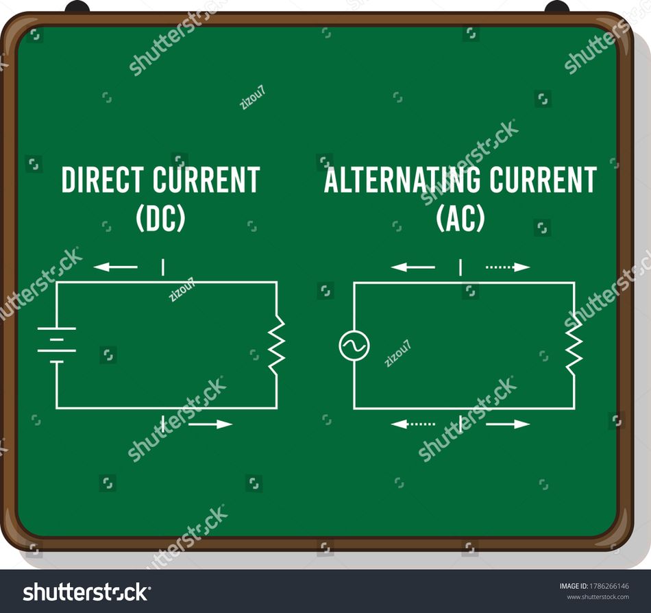
Alternating current (AC) periodically reverses direction, causing its voltage to swing between positive and negative values. In contrast, direct current (DC) flows in a single direction with a constant or slowly varying voltage level. Electronic components such as microcontrollers, memory devices, sensors, and communication modules are designed to operate on regulated DC power.
Because utility power and many generators supply AC, an intermediate conversion stage is required before this power can be used by electronic circuits. Rectification is the process that performs this conversion by reshaping an AC waveform into a unidirectional (DC) form that can later be filtered and regulated.
Diode Operation
A diode is a two-terminal semiconductor device formed by a p–n junction. Its defining characteristic is unidirectional conduction:
When forward-biased (anode at a higher potential than the cathode), the diode conducts current once the applied voltage exceeds its forward voltage drop.
When reverse-biased, the diode blocks current flow until breakdown occurs.
For standard silicon diodes, the forward voltage drop is typically 0.6–0.7 V under normal operating conditions. Germanium diodes have lower drops (≈0.3 V), while Schottky diodes, which use a metal–semiconductor junction instead of a p–n junction, exhibit even lower forward drops of 0.2–0.3 V.
This ability to conduct in one direction and block in the other is what makes diodes ideal for rectification.
Half-Wave vs Full-Wave Rectification
The simplest rectifier is the half-wave rectifier, which uses a single diode to pass only one half of the AC waveform while blocking the other. Although easy to implement, half-wave rectification is inefficient, producing a low average DC output and significant ripple.
Full-wave rectification improves efficiency by utilizing both halves of the AC cycle. This can be achieved either with a center-tapped transformer and two diodes or with a four-diode bridge configuration. The bridge rectifier is generally preferred because it does not require a center-tapped transformer and offers better transformer utilization.
Understanding these rectification fundamentals provides the foundation for analyzing how the bridge rectifier converts AC into usable DC power.
Bridge Rectifier Topology and Working Principle
To understand why bridge rectifiers are so widely used, it is helpful to look closely at their internal structure and current paths. The following section breaks down the four-diode topology and explains how the circuit redirects both halves of an AC waveform to produce a continuous DC output.
The Four-Diode Bridge Configuration
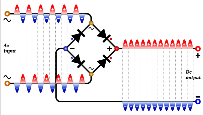
A bridge rectifier consists of four diodes arranged in a closed-loop (diamond) configuration. Two opposite nodes of the bridge are connected to the AC input, while the remaining two nodes are connected to the load. The diodes are oriented so that current through the load always flows in the same direction, regardless of the input polarity.
This configuration eliminates the need for a center-tapped transformer and allows full-wave rectification using a standard two-wire AC source.
Operation During the Positive Half-Cycle
During the positive half-cycle of the AC input, one diagonal pair of diodes becomes forward-biased while the other pair is reverse-biased. Current flows from the positive AC terminal, through the first conducting diode, across the load, and back to the AC source through the second conducting diode. As a result, the load experiences a positive voltage.
Operation During the Negative Half-Cycle
When the AC input reverses polarity during the negative half-cycle, the previously conducting diodes turn off, and the opposite diagonal pair conducts. Although the input voltage is now negative, the conducting diodes redirect the current so that it continues to flow through the load in the same direction. In effect, the negative half of the AC waveform is flipped to the positive side.
Output Waveform Characteristics
Because both halves of the AC cycle contribute to the output, the bridge rectifier produces a full-wave rectified waveform. The output is a pulsating DC signal with:
A ripple frequency equal to 2 × input AC frequency (for example, 100 Hz from a 50 Hz supply)
A higher average DC value and lower ripple compared to half-wave rectification
Average DC Output Voltage
For an ideal full-wave rectifier without filtering, the average DC output voltage is:
VDC = (2 × Vmax) / π ≈ 0.637 × Vmax
where:
Vmax is the peak value of the input AC voltage
In a practical bridge rectifier, current flows through two diodes in series during each half-cycle. With standard silicon diodes, this results in an approximate 1.4 V total forward voltage drop, which reduces the available DC output. This voltage loss is a key design consideration, particularly in low-voltage power supply applications.
Peak Inverse Voltage (PIV)
The peak inverse voltage (PIV) is the maximum reverse voltage a diode must withstand when it is not conducting. In a bridge rectifier, each diode experiences a PIV approximately equal to the peak AC input voltage:
VPIV ≈ 1.414 × VRMS
where:
VRMS is the RMS value of the AC input voltage
This PIV requirement is lower than that of a center-tapped full-wave rectifier, where each diode must withstand roughly twice the peak voltage, making the bridge topology more practical and cost-effective for many designs.
Recommended reading: Diode Schematic: Theory, Design and Practical Implementation
Types of Bridge Rectifiers
Bridge rectifiers are available in several configurations, each designed to meet specific power, control, and efficiency requirements. Understanding these variants helps engineers select the most appropriate rectifier topology for a given application.
Single-Phase Bridge Rectifier
The single-phase bridge rectifier is the most common rectifier configuration. It uses four diodes arranged in a bridge to convert single-phase AC into full-wave DC. Because it does not require a center-tapped transformer, it offers better transformer utilization and simpler wiring.
Single-phase bridge rectifiers are widely used in:
Low- and medium-power AC–DC power supplies
Consumer electronics and adapters
Embedded systems and control circuits
This topology is inexpensive, reliable, and easy to implement, making it the default choice for most general-purpose rectification needs.
Three-Phase Bridge Rectifier
A three-phase bridge rectifier uses six diodes arranged so that two diodes conduct at any given time—one from the positive group and one from the negative group. This configuration converts three-phase AC into DC with significantly reduced ripple and higher average output voltage.
Key characteristics include:
Ripple frequency equal to 6 × the AC supply frequency
Lower ripple amplitude compared to single-phase rectifiers
Higher power-handling capability
Three-phase bridge rectifiers are commonly used in:
Industrial motor drives
Welding equipment
High-power DC supplies
Electric vehicle charging systems
Uncontrolled Bridge Rectifier
An uncontrolled bridge rectifier uses only diodes, meaning conduction occurs automatically based on the input voltage polarity. The output voltage depends entirely on the AC source and the load, with no active control.
These rectifiers are typically used in:
Fixed-voltage power supplies
Battery chargers with external regulation
Front-end rectification for linear or switching regulators
Uncontrolled rectifiers are valued for their simplicity, low cost, and robustness.
Half-Controlled Bridge Rectifier (Semi-Converter)
A half-controlled bridge rectifier replaces one diagonal pair of diodes with silicon-controlled rectifiers (SCRs), while the other pair remains diodes. By adjusting the firing angle of the SCRs, engineers can control the average DC output voltage.
Key features:
Partial control over output voltage
Lower cost and complexity than fully controlled rectifiers
Unidirectional power flow
Half-controlled rectifiers are commonly used in:
Adjustable battery chargers
DC motor speed control
Industrial heating and power control applications
Fully Controlled Bridge Rectifier
In a fully controlled bridge rectifier, all four diodes are replaced with SCRs. By controlling the firing angle of each SCR pair, the average DC output voltage can be precisely regulated.
Important characteristics include:
Full control of output voltage and current
Ability to operate as an inverter when the firing angle exceeds 90 degrees
Bidirectional power flow capability
Fully controlled rectifiers are used in:
Variable-speed motor drives
Regenerative braking systems
High-voltage DC (HVDC) transmission
Industrial power conversion systems
Synchronous Rectifier
A synchronous rectifier replaces diodes with actively controlled MOSFETs. Because MOSFETs can have very low on-resistance, conduction losses are dramatically reduced compared to diode-based rectifiers.
Advantages include:
Extremely low voltage drop
High efficiency, especially at low output voltages
Reduced heat generation
Synchronous rectification is widely used in:
High-current, low-voltage DC–DC converters
CPU and FPGA power supplies
High-efficiency switching power supplies
This approach requires additional control circuitry but delivers superior efficiency in modern power electronics designs.
Practical Design Considerations
Designing a reliable bridge rectifier involves more than connecting four diodes. Engineers must account for voltage ratings, current handling, ripple reduction, heat dissipation, and safety to ensure stable and efficient operation under real-world conditions.
Selecting Rectifier Diodes
Choosing the correct diodes is critical to rectifier performance and longevity. Key parameters include:
Peak Inverse Voltage (PIV)
Each diode must withstand the maximum reverse voltage when it is not conducting. In a bridge rectifier, the minimum PIV rating should be:
VPIV ≥ 1.414 × VRMS
For safety margin and transient protection, designers typically select diodes rated at 2 to 3 times the expected peak voltage.
Forward Current Rating
The diode’s average forward current rating must exceed the maximum load current. Designers should also account for surge current, which occurs when filter capacitors charge at power-up. Many rectifier diodes are rated for surge currents several times higher than their continuous current rating.
Forward Voltage Drop
Lower forward voltage reduces power loss and heat generation. Standard silicon diodes drop approximately 0.6–0.7 V per diode, resulting in about 1.2–1.4 V loss in a bridge rectifier. Schottky diodes offer lower drops (0.2–0.3 V) but typically have lower voltage ratings and higher leakage currents.
Reverse Recovery Time
In high-frequency or switch-mode applications, diodes must switch off quickly when reverse-biased. Standard rectifier diodes are unsuitable for high-frequency operation; fast-recovery or Schottky diodes are preferred to minimize switching losses and electromagnetic interference.
Recommended reading: Rectifier Diode: Revolutionizing Electrical Applications with Advanced Semiconductor Technology
Smoothing and Filtering
The output of a bridge rectifier is a pulsating DC voltage and must be smoothed before use in regulation or direct application. The most common method is a reservoir (smoothing) capacitor connected across the load.
The approximate ripple voltage for a full-wave rectifier with a capacitor-input filter is:
Vr ≈ I / (f × C)
where:
Vr is the peak-to-peak ripple voltage
I is the load current
f is the ripple frequency (2 × mains frequency)
C is the filter capacitance
Larger capacitance reduces ripple but increases cost, size, and inrush current. For higher current loads or lower ripple requirements, designers may use:
LC or pi (π) filters
Multiple capacitors in parallel
Active post-regulation using switching converters
Voltage Regulation
Most electronic circuits require a stable DC voltage that does not vary with load or input fluctuations. Rectifiers are therefore usually followed by a voltage regulation stage.
Linear regulators (such as the 78xx series) are simple and low-noise but dissipate excess voltage as heat.
Switching regulators (buck, boost, or buck-boost converters) provide much higher efficiency, especially when the input-to-output voltage difference is large.
The rectified and filtered voltage must remain above the regulator’s minimum input requirement, even under worst-case ripple and load conditions.
Thermal Management
Bridge rectifiers dissipate power due to diode forward voltage drops. The approximate power dissipation is:
P ≈ I × VF(total)
For example, a 3 A load and a 1.4 V bridge drop result in about 4.2 W of heat. Without proper heat sinking, this can lead to thermal runaway and device failure.
Thermal design considerations include:
Selecting rectifiers with adequate current margin
Using heatsinks or metal-backed bridge modules
Ensuring sufficient airflow and PCB copper area
Protection and Safety
Rectifiers connected to AC mains must comply with electrical safety and electromagnetic compatibility (EMC) requirements. Common protective measures include:
Fuses or circuit breakers for overcurrent protection
MOVs or TVS diodes for surge suppression
Snubber networks to reduce voltage spikes
Isolation transformers to protect low-voltage circuitry
Proper PCB layout, grounding, and shielding help reduce electromagnetic interference, particularly when switching regulators follow the rectifier.
Advanced Diode Technologies
As power electronics have evolved toward higher efficiency, higher switching speeds, and greater power density, traditional silicon rectifier diodes have increasingly been supplemented—or replaced—by advanced diode technologies. These modern devices address the limitations of conventional diodes, particularly in high-frequency, high-efficiency, and high-voltage applications.
Schottky Barrier Diodes
Schottky diodes use a metal–semiconductor junction rather than a p–n junction. This structure results in a much lower forward voltage drop and extremely fast switching behavior.
Key advantages:
Forward voltage drop is typically 0.2–0.4 V
Negligible reverse recovery time
High efficiency in low-voltage applications
Limitations:
Lower reverse voltage ratings compared to silicon diodes
Higher reverse leakage current, especially at elevated temperatures
Schottky diodes are widely used in:
Low-voltage bridge rectifiers
Switch-mode power supplies (SMPS)
High-current DC–DC converters
Fast-Recovery and Ultrafast Diodes
Fast-recovery diodes are optimized to reduce reverse recovery time, making them suitable for rectification at higher frequencies than standard silicon diodes.
Key characteristics:
Reverse recovery times in the tens of nanoseconds
Lower switching losses compared to standard rectifiers
Improved EMI performance
These diodes are commonly used in:
High-frequency SMPS front-end rectification
Inverters and motor drives
Power factor correction (PFC) circuits
Silicon Carbide (SiC) Schottky Diodes
Silicon Carbide (SiC) diodes represent a major advancement in rectification technology. They combine the low-loss benefits of Schottky diodes with very high voltage and temperature capability.
Advantages include:
Virtually zero reverse recovery loss
High reverse voltage ratings (600 V to several kV)
Operation at junction temperatures above 175°C
Excellent efficiency at high switching frequencies
SiC diodes are increasingly used in:
High-efficiency AC–DC power supplies
Electric vehicle onboard chargers
Solar inverters and energy storage systems
Industrial and aerospace power electronics
Recommended reading: Understanding Silicon Controlled Rectifiers: Theory, Design and Practical Implementations
Gallium Nitride (GaN) Devices in Rectification
While GaN devices are primarily known for switching transistors, GaN-based rectification—often implemented through synchronous rectification—offers exceptional performance in high-frequency applications.
Key benefits:
Extremely low conduction and switching losses
Very high switching speed
Reduced the size of the magnetic and filtering components
GaN rectification techniques are commonly applied in:
High-density power adapters
Data center power supplies
Fast chargers and compact converters
Synchronous Rectification Using MOSFETs
Rather than relying on diodes, synchronous rectification uses controlled MOSFETs to conduct current during rectification intervals. Because MOSFET on-resistance can be extremely low, conduction losses are dramatically reduced.
Advantages:
Equivalent voltage drop is often below 50 mV
High efficiency at low output voltages
Improved thermal performance
Trade-offs:
Increased circuit complexity
Requires precise timing and control circuitry
Synchronous rectification is a cornerstone of modern high-efficiency power supply design.
Impact on Bridge Rectifier Design
The adoption of advanced diode technologies allows designers to:
Reduce conduction and switching losses
Improve thermal performance and reliability
Increase power density and efficiency
Meet stricter energy efficiency and regulatory standards
Modern PCB manufacturing and assembly quality play a critical role in fully realizing these benefits, as high-speed and wide-bandgap devices demand precise layouts, controlled impedance, and robust thermal design.
Controlled Bridge Rectifiers and Power Control
Rectifier circuits can be broadly classified based on the type of switching devices they use and the level of control they offer over the DC output. From simple diode-based designs to fully controllable thyristor bridges, each approach provides different trade-offs in cost, complexity, and performance.
Uncontrolled vs. Controlled Rectification
Uncontrolled rectifiers use only diodes as their switching elements. Conduction occurs automatically whenever a diode is forward-biased, meaning the output voltage and waveform are determined solely by the AC input and the load conditions. There is no active control over the average DC output.
In contrast, controlled rectifiers employ silicon-controlled rectifiers (SCRs), also known as thyristors. Unlike diodes, SCRs conduct only when they are forward-biased and receive a gate trigger. By adjusting the firing angle—the point in the AC cycle at which an SCR is triggered—engineers can precisely regulate the average DC output voltage and power delivered to the load.
Half-Controlled Bridge Rectifiers
A half-controlled bridge rectifier replaces one diagonal pair of diodes with SCRs, while the remaining two devices are standard diodes. During the half-cycle controlled by the SCRs, conduction begins only after a gate pulse is applied. During the opposite half cycle, the diodes conduct automatically.
By varying the firing angle between 0° and 180°, the effective conduction interval is adjusted, allowing control over the average DC output voltage. This topology offers a good balance between performance and cost, as it requires fewer controlled devices and simpler gate circuitry than a fully controlled bridge.
However, half-controlled rectifiers support only unidirectional power flow and cannot produce a negative output voltage, limiting their use in applications requiring regeneration or inversion.
Fully Controlled Bridge Rectifiers
In a fully controlled bridge rectifier, all four diodes are replaced with SCRs. Each pair of SCRs is triggered in a controlled manner during both the positive and negative half cycles of the AC input, allowing symmetrical and precise regulation of the output.
When the firing angle is less than 90°, the rectifier operates in normal rectification mode. When the firing angle exceeds 90°, the average DC output voltage becomes negative, and the converter operates as an inverter, feeding energy back into the AC source.
This capability makes fully controlled rectifiers essential in:
Variable-speed motor drives
Regenerative braking systems
High-voltage DC (HVDC) transmission
Industrial power control applications
The main challenges include more complex gate-drive circuitry, proper commutation control, and protection against high dv/dt and di/dt, which can cause unintended triggering.
Firing Angle Control and Harmonics
While firing angle control enables flexible power regulation, it also distorts the input current waveform and introduces harmonics into the AC supply. These harmonics can reduce power quality, increase losses, and cause interference with other equipment.
To address these issues, engineers may implement:
Passive line filters
Active front-end converters
Power factor correction (PFC) stages
Modern controlled rectifier systems often use digital controllers, such as microcontrollers, DSPs, or FPGAs, to generate precise gate signals. These controllers also enable closed-loop feedback, ensuring stable output regulation under varying input voltage and load conditions.
Applications of Bridge Rectifiers
Bridge rectifiers form the foundation of AC–DC power conversion across a wide range of electrical and electronic systems. From milliwatt-level embedded electronics to megawatt-scale industrial and energy systems, their ability to deliver reliable DC power makes them indispensable. Understanding these applications helps engineers specify appropriate voltage ratings, current capacity, thermal performance, and rectifier topology.
Power Supply Units and AC–DC Adapters
The most widespread use of bridge rectifiers is in AC–DC power supplies. Nearly every wall adapter, charger, and power brick contains a bridge rectifier to convert mains AC into DC before filtering and regulation.
In low-power linear supplies, a diode bridge is followed by a bulk capacitor and a linear regulator, providing a simple and low-noise solution. In high-efficiency switch-mode power supplies (SMPS), the bridge rectifier feeds a high-frequency converter stage, often combined with power factor correction (PFC) for regulatory compliance.
Typical applications include:
Consumer electronics such as televisions, radios, and audio systems
Laptop and mobile device chargers
Networking and office equipment
Battery Charging Systems
Bridge rectifiers play a central role in battery charging circuits for chemistries such as lead-acid, lithium-ion, and nickel-based cells. The rectifier converts AC input into DC, which is then conditioned by charge-control circuitry to regulate current, voltage, and charging profile.
In high-current chargers, such as automotive battery chargers, backup power systems, and uninterruptible power supplies (UPS), rectifier bridges are often implemented as packaged modules mounted on heat sinks to handle large conduction losses and surge currents.
Key considerations in these systems include:
Surge current capability during capacitor charging
Thermal management under continuous load
Efficiency and voltage drop, especially in low-voltage battery systems
DC Motor Drives and Industrial Power Equipment
Many DC motor and industrial drive systems rely on rectified AC power. Single-phase bridge rectifiers are common in small motors used in fans, pumps, and appliances, while three-phase bridge rectifiers supply high-power industrial motors and drives.
In applications such as:
Conveyor systems
Machine tools
Elevators and cranes
Welding equipment
Bridge rectifiers provide a stable DC bus. When combined with controlled rectifiers or downstream converters, they enable variable-speed motor control by adjusting the average DC voltage supplied to the motor armature or inverter stage.
Signal Demodulation and Communications
Bridge rectifiers can also be used for signal demodulation, particularly in amplitude-modulated (AM) systems. By rectifying the carrier signal, the envelope of the modulation can be extracted through filtering, converting an AC signal into a usable baseband DC or low-frequency signal.
While modern communication systems often use digital demodulation techniques, diode bridge rectifiers remain relevant in:
Low-frequency analog receivers
Instrumentation circuits
Educational and legacy communication systems
Their simplicity and predictability make them suitable for basic detection and envelope extraction tasks.
Industrial Control and Automation Systems
Industrial automation relies heavily on stable DC power for programmable logic controllers (PLCs), sensors, actuators, and communication interfaces. Bridge rectifiers convert single-phase or three-phase mains power into DC for these subsystems.
They are also integral to:
Variable frequency drives (VFDs)
Inverters and rectifier–inverter combinations
Industrial UPS and backup power units
To meet harsh operating conditions, industrial bridge rectifiers are often encapsulated, mechanically ruggedized, and equipped with screw or busbar terminals for secure, low-resistance connections.
Renewable Energy and Power Grid Applications
In renewable energy systems, bridge rectifiers enable the conversion of variable AC sources into DC for storage or grid interaction. Examples include:
Wind turbine generators
Micro-hydro systems
Auxiliary AC outputs from solar inverters
High-power three-phase bridge rectifiers operate at kilowatt to megawatt levels in these systems. The adoption of wide-bandgap devices such as silicon carbide (SiC) diodes significantly reduces switching losses, improves thermal performance, and increases overall system efficiency.
Consumer Electronics and Embedded Systems
In embedded and digital systems, bridge rectifiers often appear at the front end of the power architecture. Even when the final operating voltage is only a few volts, rectification may precede a DC–DC converter or low-dropout regulator.
Designers working with:
Microcontrollers
FPGAs
Sensors and IoT devices
benefit from understanding rectifier behavior to optimize efficiency, reduce noise, and ensure sufficient voltage headroom for downstream regulation stages.
Market Statistics and Industry Trends
Bridge rectifiers are not just textbook circuits—they represent a measurable and growing segment of the global power electronics market, driven by demand for efficient AC-to-DC conversion across industries and applications.
Market Size and Growth
Recent market research reports show that the global bridge rectifier market is expanding steadily:
One industry forecast estimates the bridge rectifier market at approximately USD 820 million in 2024, with growth to about USD 864.8 million in 2025 and USD 1.19 billion by 2031, representing a compound annual growth rate (CAGR) of around 5.46 % through the forecast period.
Another analysis of diode bridge rectifiers projects the broader market to grow from nearly USD 0.93 billion in 2024 to about USD 1.63 billion by 2035, with a similar mid-single-digit CAGR, reflecting sustained demand across applications.
Broader market reports covering full-wave bridge rectifiers suggest even larger total addressable markets—valued in the USD 1.3-1.4 billion range in 2024 and forecast to reach around USD 2.5 billion by 2035, driven by technology adoption and expanded end-use sectors.
These estimates vary depending on segmentation and reporting methodology, but they consistently indicate steady growth at mid-single-digit CAGRs over the coming decade.
Growth Drivers
Several factors are fueling this market expansion:
Ubiquitous power conversion needs: Bridge rectifiers are essential in almost every AC-to-DC conversion stage, from consumer chargers to industrial power supplies.
Electrification trends: Adoption of electric and hybrid vehicles, which require multiple rectification stages for battery charging and onboard systems, boosts demand.
Renewable energy growth: Solar inverters, wind turbine converters, and energy storage systems increasingly rely on efficient rectification.
Industrial automation: Factory electrification and automated systems require robust, high-reliability DC power rails.
Miniaturization and efficiency: Compact designs with surface-mounted and advanced semiconductor technologies support IoT, portable electronics, and high-efficiency power supplies.
Challenges and Market Constraints
Despite growth opportunities, the industry faces challenges such as:
Raw material price volatility is affecting margins and component costs.
Thermal management constraints in high-power designs.
Environmental and regulatory compliance, which increases lifecycle costs and design complexity.
Competitive Landscape
The bridge rectifier market includes a mix of established semiconductor manufacturers and specialized component vendors. Leading companies designing and supplying bridge rectifiers and related power components include:
ON Semiconductor
Infineon Technologies
Vishay Intertechnology
Diodes Incorporated
IXYS (now part of Littelfuse and other portfolios)
STMicroelectronics
Microchip Technology
Taiwan Semiconductor Manufacturing Company (TSMC)
Panasonic and other global power electronics players
These companies offer a range of products across voltage ratings, current capacities, packages, and technologies (including silicon, Schottky, and advanced materials), helping address diverse application needs from low-power consumer devices to high-power industrial systems.
Outlook
Across market reports, the outlook remains positive: bridge rectifier demand is expected to grow steadily as electrification, automation, and energy efficiency trends continue to accelerate. While exact dollar figures vary by source, consistent mid-single-digit CAGRs reflect a healthy long-term trajectory for this fundamental power conversion component.
Design Example: Building a 5 V Regulated Power Supply
To demonstrate how a bridge rectifier operates in a real circuit, consider the design of a 5 V regulated DC power supply using a 12 V RMS, mains-isolated transformer. This example highlights the key calculations and design decisions involved in practical rectifier-based power supplies.
Step 1: Determine the Peak Secondary Voltage
A transformer secondary rated at 12 V RMS produces a higher peak voltage given by:
Vmax = √2 × VRMS
Vmax = 1.414 × 12 ≈ 16.97 V
This is the maximum voltage available before rectification losses.
Step 2: Account for Bridge Rectifier Diode Drops
In a bridge rectifier, current flows through two diodes in series during each half cycle. For standard silicon diodes, the total forward voltage drop is approximately:
Vdrop ≈ 2 × 0.7 V = 1.4 V
The approximate peak DC voltage after rectification is therefore:
VDC_peak ≈ Vmax − Vdrop
VDC_peak ≈ 16.97 − 1.4 ≈ 15.57 V
Step 3: Select the Filter Capacitor
Assume:
Load current: I = 0.5 A
Allowable ripple voltage: Vr = 0.5 V
Ripple frequency for full-wave rectification on 50 Hz mains: f = 100 Hz
The required smoothing capacitance is estimated using:
C = I / (f × Vr)
C = 0.5 / (100 × 0.5)
C = 0.01 F
This corresponds to 10,000 µF (10 mF). A capacitor rated at 25 V or higher is recommended to provide voltage margin and long-term reliability.
Step 4: Choose the Rectifier Diodes
Each diode must withstand a peak inverse voltage (PIV) at least equal to the transformer’s peak voltage:
VPIV ≥ Vmax ≈ 17 V
For a safety margin, a 50 V PIV rectifier is appropriate. Options include:
A packaged bridge rectifier rated for 1 A or higher
Four discrete diodes, such as 1N5408, which offer ample voltage and current margin
Step 5: Add Voltage Regulation
A common linear regulator, such as the LM7805 is used to maintain a stable 5 V output. This regulator requires a minimum input voltage of approximately 7 V to remain in regulation.
With a rectified and filtered input of about 15 V, sufficient headroom exists to ensure reliable operation under load and ripple conditions.
Step 6: Thermal Considerations
The linear regulator dissipates power equal to the voltage drop across it multiplied by the load current:
P = (Vin − Vout) × I
P ≈ (15 − 5) × 0.5
P ≈ 5 W
A heatsink is essential to prevent thermal shutdown and ensure long-term reliability. Without adequate cooling, the regulator may overheat even at moderate load currents.
Step 7: Safety and Protection
For safe and compliant operation, the design should include:
A primary-side fuse for overcurrent protection
Transformer isolation from mains
Proper enclosure and insulation
Optional LED power indicator
Bleeder resistor across the filter capacitor to safely discharge stored energy when power is removed
Comparison with Other Rectifier Topologies
While the bridge rectifier is the most widely used full-wave rectification method, it is not the only option. Comparing it with alternative rectifier topologies—particularly the center-tap full-wave rectifier and the half-wave rectifier—highlights why the bridge configuration dominates modern power supply design.
Bridge Rectifier vs. Center-Tapped Full-Wave Rectifier
A center-tapped full-wave rectifier uses a transformer with a center-tapped secondary winding and two diodes. Each half of the secondary winding supplies one half of the rectified waveform. In contrast, a bridge rectifier uses four diodes and a standard two-wire secondary, eliminating the need for a center tap.
Key differences are summarized below:
Aspect | Bridge Rectifier | Center-Tapped Full-Wave Rectifier |
Diodes used | 4 | 2 |
Transformer requirement | Standard secondary (no center tap) | Center-tapped secondary required |
Peak Inverse Voltage (PIV) per diode | ≈ Vmax | ≈ 2 × Vmax |
Forward voltage drop | Two diodes conduct per half cycle | One diode conducts per half cycle |
DC output voltage | Slightly higher (fully secondary utilized) | Slightly lower |
Transformer utilization | High | Lower |
Cost and size | Lower transformer cost, compact | Larger, more expensive transformer |
Typical applications | Power supplies, chargers, and general electronics | Low-power circuits, signal processing |
Although the center-tap rectifier uses fewer diodes and has a lower conduction drop, it requires a bulkier and more expensive transformer. In addition, only half of the secondary winding conducts at any given time, reducing transformer utilization. The bridge rectifier’s compatibility with standard transformers makes it more economical and practical for most designs.
Half-Wave Rectifier vs. Bridge Rectifier
A half-wave rectifier uses a single diode and conducts during only one half of the AC cycle. As a result, much of the input energy is wasted, and the output contains a large ripple. A bridge rectifier, by contrast, uses both halves of the AC waveform, delivering higher efficiency and a smoother DC output.
Performance comparison:
Characteristic | Half-Wave Rectifier | Bridge Rectifier (Full-Wave) |
Diodes used | 1 | 4 |
DC output (ideal) | Vmax / π | 2 × Vmax / π |
Ripple factor | 1.21 | 0.482 |
Rectification efficiency | ≈ 40 % | ≈ 81 % |
Transformer utilization factor | 0.287 | 0.693 |
Output quality | Highly pulsating | Smoother DC |
Typical applications | Indicators, signal detection | Power supplies, chargers, DC loads |
Because it uses only half of the input waveform, the half-wave rectifier delivers lower average DC voltage, higher ripple, and poorer efficiency. The bridge rectifier effectively doubles the usable output for the same AC input and significantly reduces ripple, justifying the higher diode count in most applications.
Advantages and Disadvantages of Bridge Rectifiers
Advantages
Utilizes both half cycles of the AC waveform
Higher rectification efficiency
No need for a center-tapped transformer
Better transformer utilization
Higher average DC output voltage
Smoother DC output after filtering
Disadvantages
Requires four diodes
Two diode drops per conduction path reduce the output voltage
Higher power dissipation and heat generation
Slightly higher component count and cost
Future Directions and Industry Outlook
Bridge rectifiers remain a foundational technology in electronics, yet ongoing innovation in materials, integration, and control is shaping the next generation of rectification systems. Key trends include:
1. Wide-Bandgap Semiconductor Devices
Emerging materials such as silicon carbide (SiC) and gallium nitride (GaN) enable diodes with higher breakdown voltages, lower forward voltage drops, and ultra-fast switching speeds. These characteristics make high-efficiency bridge rectifiers practical for electric vehicle chargers, renewable energy systems, high-power industrial drives, and data center power supplies.
2. Integrated Power Modules
Modern power electronics increasingly leverage multi-chip modules that combine bridge rectifiers, MOSFETs, synchronous rectifiers, drivers, and controllers in compact packages. This integration reduces board space, simplifies thermal management, and shortens design cycles for engineers developing AC–DC and DC–DC converters.
3. Digital Control and Monitoring
Microcontrollers, DSPs, and FPGA-based controllers enable precise gate or firing-angle control in controlled rectifiers. They also allow real-time monitoring of current, voltage, and temperature, along with communication to supervisory systems. These capabilities facilitate smart grids, IoT-enabled power supplies, and adaptive load management.
4. Energy Harvesting Applications
Bridge rectifiers are integral in micro-energy harvesting circuits, converting mechanical vibrations, RF energy, or piezoelectric outputs into usable DC for wireless sensors. Using ultra-low-drop diodes or synchronous rectifiers maximizes the harvested energy, extending battery life and enabling autonomous sensor networks.
5. Environmental and Regulatory Considerations
Efficiency regulations, electromagnetic compatibility standards, and sustainability mandates are driving the design of rectifiers with lower losses, reduced hazardous materials, and longer operational lifetimes. Compliance with programs such as Energy Star encourages adoption of high-efficiency rectification in both consumer and industrial products.
Conclusion
A solid understanding of bridge rectifiers is crucial for engineers working on power supplies, embedded systems, and high-power industrial equipment. By using four diodes to rectify both halves of an AC waveform, the bridge rectifier delivers a higher average DC voltage and lower ripple compared to half-wave rectifiers.
Practical designs require careful consideration of diode forward voltage drops, peak inverse voltage (PIV), current ratings, and thermal management. Incorporating smoothing capacitors and voltage regulators further stabilizes the DC output. Modern enhancements—including Schottky diodes, wide-bandgap semiconductors, and synchronous rectifiers—boost efficiency and overall performance. Additionally, controlled rectifiers using SCRs or MOSFETs allow variable voltage regulation and bidirectional power flow, expanding their versatility.
Bridge rectifiers remain ubiquitous, from small AC adapters powering microcontrollers to high-power three-phase modules in industrial systems. With the rising demand for consumer electronics, electric vehicles, and renewable energy, the rectifier market continues to grow, driving innovation in materials, integration, and intelligent control. By mastering the principles, practical design considerations, and applications discussed here, engineers and students are well-equipped to implement bridge rectifiers effectively and stay ahead in the evolving landscape of power conversion technology.
Frequently Asked Questions (FAQ)
1. Why are four diodes used in a bridge rectifier?
Four diodes arranged in a bridge ensure that, regardless of the AC input polarity, two diodes conduct in series to direct current through the load in the same direction. This eliminates the need for a center‑tapped transformer and enables full-wave rectification.
2. What is the efficiency of a bridge rectifier?
The theoretical efficiency of a bridge rectifier is approximately 81%. In real-world circuits, efficiency is slightly lower due to forward voltage drops of the diodes and losses in filtering or voltage regulation.
3. How do I select the right bridge rectifier for my circuit?
Select a rectifier with:
Peak inverse voltage (PIV) ≥ peak AC input (with margin).
Forward current rating > maximum load current (including surge).
Consider forward voltage drop, recovery time, and package/heat sinking.
For high-efficiency designs, use Schottky diodes or synchronous rectifiers.
4. Can bridge rectifiers be paralleled to handle more current?
Paralleling diodes is possible but risky due to current imbalance and thermal runaway. It's safer to use a single rectifier module rated for the required current or add equalizing resistors. High-current modules often include integral heat sinks.
5. What happens if one diode fails in a bridge rectifier?
Open diode: The circuit behaves like a half-wave rectifier, causing increased ripple and reduced DC output.
Shorted diode: May short-circuit the AC source, damaging components or blowing fuses.
Proper fusing and quality components mitigate these risks.
6. Why does the output of a bridge rectifier have ripple even after rectification?
Rectification converts the negative half of AC to positive, producing a pulsating DC waveform. Without filtering, the voltage drops to zero between peaks. Capacitors or inductors reduce ripple, but some remains unless active voltage regulation is used.
7. Is it possible to build a bridge rectifier without a transformer?
Yes, but a direct connection to the mains is unsafe for low-voltage electronics, as it provides no isolation. Always use an isolated transformer or AC–DC converter when user safety is a concern. Non-isolated rectifiers are used only in sealed appliances inaccessible to users.
References
[1] “Bridge Rectifiers,” Electronics Tutorials. [Online]. Available: https://www.electronics-tutorials.ws/diode/diode_4.html. [Accessed: 21-Dec-2025]
[2] “Full Wave Rectifier,” *Unacademy NEET‑UG Physics Study Material*. [Online]. Available: https://unacademy.com/content/neet-ug/study-material/physics/full-wave-rectifier/ [Accessed: 21‑Dec‑2025]
[3] “Understanding Rectifier Power Supply Basics,” *Outdoor Telecom Cabinet Blog*. [Online]. Available: https://blog.outdoortelecomcabinet.com/rectifier-power-supply-basics/ [Accessed: 22-Dec-2025]
[4] “Active vs Passive Electronic Components,” NextPCB Blog. [Online]. Available: https://www.nextpcb.com/blog/active-vs-passive-electronic-components [Accessed: 22-Dec-2025]
[5] “The Basics of Diodes Explained,” *The Engineering Mindset*. [Online]. Available: https://theengineeringmindset.com/the-basics-of-diodes-explained/ [Accessed: 22-Dec-2025]
[6] “PCB Layout Bridge Rectifier: Important Design Guidelines,” *Ultra Librarian*. [Online]. Available: https://www.ultralibrarian.com/pcb-layout-bridge-rectifier-important-design-guidelines/ [Accessed: 23-Dec-2025]
[7] “Bridge Rectifier Market Size, Growth, Forecast Till 2031,” *Report Prime*, Nov. 2025. [Online]. Available: https://www.reportprime.com/bridge-rectifier-r1188 [Accessed: 23‑Dec‑2025].
in this article
1. Key takeaways2. Introduction3. Fundamentals of Rectification and Diodes4. Bridge Rectifier Topology and Working Principle5. Types of Bridge Rectifiers6. Practical Design Considerations7. Advanced Diode Technologies8. Controlled Bridge Rectifiers and Power Control9. Applications of Bridge Rectifiers10. Market Statistics and Industry Trends11. Design Example: Building a 5 V Regulated Power Supply12. Comparison with Other Rectifier Topologies13. Future Directions and Industry Outlook14. Conclusion15. Frequently Asked Questions (FAQ)16. References