Crystal Oscillator Circuit Design: Pierce Oscillator Guide for Precision Frequency Generation
A crystal oscillator circuit uses a quartz crystal and an amplifier to generate a highly stable frequency reference. This guide explains Pierce oscillator design, load capacitance, negative resistance, drive level, startup behavior, and frequency stability in microcontrollers and RF systems.

30 Jun, 2026. 17 minutes read
Key Takeaways
Quartz crystal model. A quartz crystal behaves as a high-Q resonant network comprising motional inductance (Lm), motional capacitance (Cm), motional resistance (Rm), and shunt capacitance (C0). The oscillator circuit must provide the correct load capacitance, bias conditions, and sufficient negative resistance to sustain oscillation at the specified frequency.
Pierce oscillator dominance. The Pierce oscillator is the most widely used crystal oscillator topology in microcontrollers and embedded systems. It employs an inverting amplifier, feedback resistor, and load capacitors to satisfy the Barkhausen criterion. Reliable operation depends on proper load capacitance selection and adequate negative resistance margin.
Load capacitance calculation. The effective crystal load capacitance is determined by the series combination of the two load capacitors plus parasitic capacitance. Even small deviations can shift oscillation frequency, typically by approximately −15 to −30 ppm per picofarad. PCB traces, IC pins, and package parasitics commonly contribute 2–5 pF of stray capacitance.
Feedback and damping resistors. Typical feedback resistor values range from 5–15 MΩ for 32.768 kHz tuning-fork crystals and 470 kΩ–10 MΩ for MHz-range crystals. A series damping resistor limits crystal drive level and reduces overstress; values above 10 kΩ are commonly used with watch crystals to maintain drive levels below 1 µW.
Negative resistance margin. For dependable startup across voltage, temperature, and process variations, the oscillator's negative resistance should exceed the crystal's equivalent series resistance (ESR) by at least a factor of four to ten. A practical verification method is to add series resistance until oscillation ceases and calculate the available margin.
Startup characteristics. Oscillator startup time is influenced by crystal Q, load capacitance, available negative resistance, and operating temperature. Tuning-fork crystal oscillators may require 1–5 seconds to stabilize, whereas MHz-range oscillators typically reach full amplitude within a few milliseconds. Lower load capacitance and higher startup gain generally reduce startup time.
Introduction
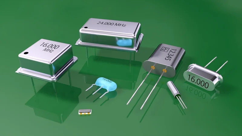
A crystal oscillator circuit combines a quartz crystal resonator with an amplifying circuit to generate a precise and stable clock signal. Owing to their high quality factor (Q), excellent frequency stability, and low phase noise, crystal oscillators are widely used in microcontrollers, communication systems, RF circuits, and other timing-critical electronic applications.
This article focuses on the circuit-level design of crystal oscillators, with particular emphasis on the Pierce oscillator topology, the most widely used crystal oscillator configuration in modern embedded systems. Topics covered include crystal equivalent circuits, load capacitance selection, negative resistance, drive-level considerations, and oscillator startup behavior.
Unlike LC and RC oscillators, quartz crystal oscillators derive their frequency stability from the mechanical resonance of the crystal itself. However, achieving the specified frequency accuracy requires careful oscillator design. Incorrect load capacitance, excessive drive power, or insufficient negative resistance can result in frequency error, prolonged startup times, accelerated aging, or unreliable operation.
Most modern microcontrollers incorporate an internal inverter that simplifies Pierce oscillator implementation. Understanding how the crystal's motional parameters interact with the surrounding circuit enables engineers to optimize startup reliability, minimize frequency drift, and achieve ppm-level timing accuracy across voltage, temperature, and manufacturing variations.
Crystal Equivalent Circuit Review
Quartz crystals are precision-cut slices of quartz oriented to achieve a specific temperature coefficient and frequency stability. The crystal equivalent circuit consists of a motional inductance (Lm), motional capacitance (Cm), and motional resistance (Rm) connected in series. This motional branch models the mechanical resonance of the vibrating quartz element. In parallel with the motional branch is the shunt capacitance (C0), which represents the capacitance of the crystal electrodes, package, and mounting structure.
The resulting impedance response exhibits two characteristic resonant frequencies:
Series resonance (fs): At this frequency, the reactances of Lm and Cm cancel, and the crystal behaves as a resistive element with an impedance approximately equal to Rm.
fs = 1 / (2π × √(Lm × Cm))
Parallel resonance (fp): At frequencies slightly above fs, the motional branch interacts with the shunt capacitance C0, producing a higher-impedance resonance.
fp ≈ fs × √(1 + Cm / C0)
Most crystal oscillator circuits operate at this parallel, or load-resonant, frequency.
Because C₀ is typically only a few picofarads for MHz crystals and approximately 1–2 pF for tuning fork crystals, the separation between fp and fs is relatively small. Crystal manufacturers specify a nominal load capacitance (CL) at which the device is calibrated. Deviations from this specified load capacitance cause frequency pulling, typically in the range of –15 to –30 ppm per picofarad.
Recommended Reading: Crystal Oscillator: Fundamentals, Models, and Design Guidelines
Pierce Oscillator Circuit
The Pierce oscillator is the most widely used crystal oscillator topology in microcontrollers, embedded systems, and discrete clock-generation circuits due to its simplicity, low component count, and reliable startup characteristics.
The circuit consists of an inverting amplifier (typically a CMOS inverter or transistor stage), a feedback resistor (Rf) that biases the amplifier in its linear operating region, two load capacitors (C1 and C2) connected from the amplifier input and output nodes to ground, and a quartz crystal placed in the feedback path. An optional series resistor (Rs) may be added to control crystal drive level.
At resonance, the amplifier contributes 180° of phase shift while the crystal feedback network provides the additional 180°, satisfying the Barkhausen phase criterion required for sustained oscillation.
Biasing and Feedback Resistor
When a CMOS inverter is used as the active element in a Pierce oscillator, it must operate in its linear region rather than as a digital switch. The feedback resistor Rf establishes this operating point by providing a DC feedback path between the output and input nodes, biasing the inverter near VDD/2.
Application notes commonly recommend feedback resistor values between 5 MΩ and 15 MΩ for 32.768 kHz tuning-fork crystals and approximately 470 kΩ to 10 MΩ for MHz-range crystals. STMicroelectronics AN2867 recommends values of 5–10 MΩ for 4–16 MHz crystal oscillators and 10–20 MΩ for low-frequency crystal applications.
Load Capacitors and Resonant Frequency
The load capacitors determine the effective load capacitance presented to the crystal and directly influence oscillation frequency accuracy.
CL ≈ (C1 × C2) / (C1 + C2) + Cstray
where:
CL = effective load capacitance
C1, C2 = external load capacitors
Cstray = combined stray capacitance from the PCB, package, and amplifier pins
For symmetric designs where C1 = C2 = C:
CL ≈ C / 2 + Cstray
Stray capacitance typically ranges from 2–5 pF in microcontroller-based designs. Crystal manufacturers commonly specify nominal load capacitances of 12.5 pF, 16 pF, 18 pF, or 20 pF. Rearranging the equation for equal-value capacitors gives:
C = 2(CL − Cstray)
For example, an 8 MHz crystal specified for an 18 pF load capacitance with 3 pF of stray capacitance requires:
C1 = C2 = 2(18 − 3) = 30 pF
Proper load-capacitor selection minimizes frequency error and ensures operation at the intended parallel-resonant frequency.
Recommended Reading: Capacitors in Series: Theory, Design Considerations and Practical Implementations
Series Resistor and Drive-Level Control
The optional series resistor (Rs) is placed between the amplifier output and the crystal. Its primary functions are to limit crystal drive current, reduce startup stress, suppress spurious oscillation modes, and improve long-term frequency stability and crystal reliability.
Unlike the load capacitors, the series resistor is not typically selected using a precise design equation. Instead, its value is determined by the oscillator's drive-level requirements, crystal characteristics, and the output drive capability of the amplifier. Excessive drive power can accelerate crystal aging, increase frequency drift, and, in extreme cases, damage the crystal element.
For 32.768 kHz tuning-fork crystals, Rs values typically range from 10 kΩ to 50 kΩ to maintain the low drive levels required by these high-Q resonators. For MHz-range crystal oscillators, values from several tens of ohms to a few hundred ohms are commonly used to reduce drive level while preserving sufficient loop gain for reliable startup.
The optimal value is generally established through measurement of the crystal drive level and verification of startup margin under worst-case operating conditions.
Recommended Reading: PCB Design: A Comprehensive Guide to Printed Circuit Board Design - Part 1
Component Selection Example
Consider a 16 MHz STM32 oscillator using a crystal specified for a 20 pF load capacitance, with 3 pF of stray capacitance and a motional resistance of 60 Ω.
The required load capacitors can be calculated as:
C1 = C2 = 2(CL − Cstray)
= 2(20 − 3)
= 34 pF
ST AN2867 recommends a feedback resistor in the range of 5–10 MΩ for crystal oscillators operating in this frequency range [1]. A practical starting point is:
Rf = 10 MΩ
C1 = C2 = 34 pF
If crystal drive-level reduction is required, a series resistor may be added between the oscillator output and the crystal. For a 16 MHz oscillator, typical values range from several tens of ohms to a few hundred ohms, depending on the crystal characteristics, amplifier drive strength, and startup margin requirements. An initial value of approximately 300 Ω is often suitable for evaluation, but the final value should be verified through drive-level and startup testing.
This configuration provides the required load capacitance while maintaining adequate loop gain for reliable startup and stable frequency operation. Final component values should be validated against the crystal manufacturer's specifications and the microcontroller oscillator design guidelines.
Load Capacitance Matching
Accurate load-capacitance matching is essential for maintaining crystal oscillator frequency accuracy. Crystal manufacturers specify a nominal load capacitance (CL) at which the crystal is calibrated. Any deviation from this value shifts the operating frequency away from its nominal specification.
The frequency pulling sensitivity of a typical crystal is approximately –15 to –30 ppm/pF. As an example, a 2 pF load-capacitance mismatch can produce a frequency error of approximately –60 ppm. For a 16 MHz oscillator, this corresponds to:
Frequency Error = 16,000,000 × (60 × 10^-6)
= 960 Hz
The effective load capacitance is given by:
CL ≈ (C1 × C2) / (C1 + C2) + Cstray
For designs using equal-value capacitors (C1 = C2 = C), the equation simplifies to:
CL ≈ C / 2 + Cstray
Designers typically use equal capacitor values and account for PCB and device parasitics when selecting the load network. For example, a 32.768 kHz tuning-fork crystal specified for a 12.5 pF load capacitance can be paired with two 18 pF capacitors. Assuming approximately 3 pF of stray capacitance, the resulting effective load capacitance is close to the target value.
Although equal capacitor values are most common, unequal values may be used to optimize oscillator startup behavior. Reducing C1 relative to C2 decreases attenuation in the feedback network and can increase the effective loop gain available to the crystal, improving startup margin in low-gain oscillator circuits.
Stray capacitance originates from multiple sources, including microcontroller oscillator pins, crystal package capacitance, PCB traces, pads, and vias. Typical microcontroller oscillator pins contribute approximately 2–3 pF each. Because load capacitance directly affects oscillation frequency, temperature-stable NP0/C0G ceramic capacitors are recommended. Dielectrics such as X7R and Y5V exhibit larger capacitance variations with temperature, voltage, and aging and are generally unsuitable for precision crystal oscillator applications.
Recommended Reading: Capacitor Polarity: Ensuring Proper Orientation for Optimal Performance
Feedback Resistor Sizing
The feedback resistor (Rf) is a critical component in Pierce oscillator circuits because it biases the inverting amplifier into its linear operating region. Without this resistor, the amplifier input can remain floating, preventing the oscillator from establishing the small-signal conditions required for startup.
In CMOS-based oscillator circuits, Rf creates a DC feedback path between the amplifier output and input, shifting the operating point toward the midpoint of the supply voltage. This allows the inverter to behave as a high-gain analog amplifier rather than a digital switch. Once oscillation begins, the resistor has little influence on the AC behavior of the circuit but remains essential for maintaining the correct bias conditions.
The optimum value of Rf depends on the oscillator frequency, amplifier characteristics, supply voltage, and crystal type. Low-frequency tuning-fork crystals generally require higher resistance values than MHz-frequency crystals because of their lower drive levels and higher impedance.
If the feedback resistance is too low, excessive current may flow through the amplifier, increasing power consumption and potentially increasing crystal drive level. If the resistance is too high, the bias network may become ineffective, resulting in unreliable startup, particularly at low supply voltages or under adverse temperature conditions.
Most microcontroller oscillator circuits use feedback resistors in the megaohm range, with the final value selected according to the crystal manufacturer's recommendations and the microcontroller vendor's oscillator design guidelines.
Recommended Reading: Operational Amplifier: Theory, Design and Applications for Engineers
Series Damping Resistor and Drive Level
Crystal resonators are designed to operate within a specified drive-level range. Excessive drive power can increase frequency drift, accelerate aging, excite unwanted resonant modes, and in extreme cases damage the quartz element. Maintaining an appropriate drive level is therefore essential for long-term frequency stability and oscillator reliability.
The drive level represents the power dissipated within the crystal's motional resistance. Crystal manufacturers specify a maximum allowable value, which is typically much lower for 32.768 kHz tuning-fork crystals than for AT-cut crystals used in MHz-frequency oscillators.
A series damping resistor (Rs) is often added between the amplifier output and the crystal to limit current flow through the resonator. In addition to reducing crystal drive level, the resistor helps suppress startup transients and minimizes the likelihood of exciting spurious oscillation modes.
Selecting the value of Rs involves balancing two competing requirements. Increasing the resistance reduces crystal stress and lowers power dissipation, but excessive resistance also reduces loop gain and may prevent reliable oscillator startup. For this reason, Rs is typically treated as a tuning parameter that is optimized during validation testing rather than calculated from a single design equation.
In many designs, controlling crystal drive level through a series resistor is preferable to modifying the load capacitance. While reducing load capacitance can also decrease crystal current, it alters the effective load seen by the crystal and may introduce unwanted frequency error.
Negative Resistance and Oscillation Margin
A crystal oscillator starts only when the active circuit supplies sufficient energy to overcome losses within the crystal. These losses are represented by the crystal's equivalent series resistance (ESR), also known as motional resistance. The ability of the oscillator to overcome these losses is commonly described in terms of negative resistance.
From the crystal's perspective, the amplifier and feedback network appear as a source of negative resistance. When the magnitude of this negative resistance exceeds the crystal's ESR, oscillation can build from thermal noise and grow to a stable amplitude. If the available negative resistance is insufficient, the oscillator may fail to start or may exhibit intermittent operation under varying supply voltage, temperature, or manufacturing conditions.
Oscillator designers typically evaluate startup robustness using the negative resistance margin, which compares the available negative resistance with the crystal's ESR. A larger margin generally improves startup reliability and tolerance to component variation. Most manufacturers recommend maintaining a substantial safety margin rather than designing to the minimum startup threshold.
A common validation method is the series-resistor test. An external resistor is inserted in series with the crystal and gradually increased until oscillation ceases. The resulting measurement provides an indication of the oscillator's startup margin and helps verify that the design can tolerate variations in crystal characteristics and operating conditions.
If startup margin is insufficient, several design changes may improve performance. These include reducing load-capacitor values, lowering the series damping resistance, increasing amplifier drive capability, minimizing PCB parasitics, or selecting a crystal with lower ESR.
Because oscillator startup behavior is strongly influenced by temperature, supply voltage, and manufacturing tolerances, negative resistance testing should be performed across the full operating range of the final product.
Recommended Reading: Signal Integrity in High Speed Digital Systems: Theory & Practice
Startup Behavior and Settling Time
A crystal oscillator does not begin oscillating immediately when power is applied. Oscillation starts from random electrical noise present in the circuit. If the oscillator loop provides sufficient gain at the crystal's resonant frequency, these small signals are amplified and gradually build into a stable periodic waveform.
The time required for the oscillation amplitude to reach its steady-state value is known as the startup time. Startup behavior depends on several factors, including crystal quality factor (Q), equivalent series resistance (ESR), load capacitance, amplifier gain, and the available negative resistance margin.
High-Q crystals store energy efficiently and provide excellent frequency stability, but they generally require more time to reach full oscillation amplitude. This is particularly noticeable in 32.768 kHz tuning-fork crystals used in real-time clock applications, where startup times may range from hundreds of milliseconds to several seconds. In contrast, AT-cut crystals operating in the MHz range typically start within a few milliseconds because of their lower Q and higher operating frequencies.
Startup problems are often caused by insufficient oscillator margin rather than the crystal itself. Excessive load capacitance, high crystal ESR, weak amplifier drive strength, or excessive series resistance can all reduce the available loop gain and prevent oscillation from building reliably.
When startup issues occur, designers typically verify oscillator margin, reduce load-capacitor values, optimize the PCB layout, or select a crystal with lower ESR. Startup performance should always be evaluated across the full operating temperature range and supply-voltage range to ensure reliable operation under all conditions.
Colpitts and Clapp Oscillator Variants
Although the Pierce oscillator is the dominant topology in microcontrollers and embedded systems, other crystal oscillator architectures are commonly used in RF and communication equipment.
The Colpitts oscillator uses a capacitive voltage divider in the feedback network to establish the phase and gain conditions required for oscillation. This topology is widely used in RF transmitters, local oscillators, voltage-controlled oscillators (VCOs), and signal-generation circuits because it performs well at higher frequencies and can be adapted for frequency tuning applications.
The Clapp oscillator is a variation of the Colpitts design that introduces an additional capacitor in series with the resonant network. This extra component reduces the influence of transistor and stray capacitances, improving frequency stability and making the circuit less sensitive to component tolerances.
For applications requiring frequencies beyond the practical fundamental-mode limit of a crystal, overtone oscillators may be used. These circuits employ additional filtering components to force the crystal to oscillate at one of its higher-order resonant frequencies, allowing crystal-controlled operation well above the frequencies achievable with fundamental-mode devices.
Despite the availability of these alternative topologies, the Pierce oscillator remains the preferred choice for most microcontroller clock circuits because it offers low component count, low power consumption, and straightforward implementation.
Common Crystal Oscillator Failure Modes
Crystal oscillators are generally reliable, but several design and implementation issues can affect startup, frequency accuracy, and long-term stability.
Startup Failure or Intermittent Oscillation
One of the most common problems is an oscillator that fails to start or starts only under certain conditions. This behavior is often caused by insufficient negative resistance margin, excessive load capacitance, high crystal ESR, or inadequate amplifier drive strength. Temperature variations and supply-voltage changes can further reduce startup reliability in marginal designs.
Frequency Offset
Crystal oscillators achieve their specified accuracy only when operating with the intended load capacitance. Errors in capacitor selection, PCB parasitics, or package capacitance can shift the oscillation frequency away from its nominal value. Even a small capacitance mismatch can introduce frequency errors measured in tens of parts per million (ppm).
Spurious Oscillation Modes
Excessive crystal drive level, poor PCB layout, or unintended parasitic reactances can excite unwanted resonant modes. These oscillations may occur at harmonics or nearby resonant frequencies and can degrade signal quality or cause unstable operation.
Excessive Jitter and Phase Noise
Noise on the power supply or coupling from nearby high-speed signals can introduce timing uncertainty into the oscillator output. This effect appears as jitter in digital systems and phase noise in RF applications. Poor power-supply filtering and inadequate grounding are common contributors.
Long-Term Frequency Drift
Mechanical stress, contamination, temperature cycling, and natural crystal aging gradually alter the resonant characteristics of the quartz element. Excessive drive level can accelerate this process and reduce long-term frequency stability.
PCB Layout Guidelines for Crystal Oscillators
Even a well-designed oscillator circuit can perform poorly if the PCB layout introduces excessive parasitic capacitance, noise coupling, or signal loss. Because crystal oscillators operate with small signal amplitudes and high impedance nodes, layout quality has a direct impact on startup reliability and frequency accuracy.
Keep Oscillator Connections Short
The crystal and load capacitors should be placed as close as possible to the microcontroller or oscillator pins. Short, symmetric traces minimize stray capacitance and reduce susceptibility to external noise sources.
Provide a stable ground reference
A continuous ground plane beneath the oscillator circuitry helps control return-current paths and reduces electromagnetic interference. Some high-performance designs also use grounded guard traces around sensitive oscillator nodes to minimize coupling from nearby signals.
Isolate the Oscillator from Noise Sources
High-speed digital signals, switching regulators, clocks, and RF circuits should be routed away from the crystal network. Noise coupled into the oscillator loop can increase jitter, degrade phase noise performance, or interfere with startup.
Use Appropriate Components
Load capacitors should use temperature-stable NP0/C0G dielectric materials because their capacitance remains relatively constant across temperature and voltage variations. Components associated with the oscillator network, including the feedback resistor and any series damping resistor, should be placed close to the amplifier pins to minimize parasitic effects.
Consider Environmental Factors
Temperature gradients, mechanical vibration, humidity, and board flexing can all affect oscillator performance. Crystals should be positioned away from heat-generating components, and harsh-environment applications may require additional protection such as conformal coating or environmental sealing.
Recommended Reading: How to Design a PCB Layout: A Comprehensive Guide
Example of Crystal Oscillator Implementations
Most modern microcontrollers include an integrated amplifier designed specifically for Pierce oscillator operation. While component values vary between device families, the underlying design approach remains largely the same: match the crystal's specified load capacitance, provide adequate startup margin, control crystal drive level, and minimize PCB parasitics.
STM32 Microcontrollers
STM32 devices commonly use external high-speed crystals in the 4–25 MHz range for system clock generation and 32.768 kHz tuning-fork crystals for real-time clock functions. Typical implementations use symmetrical load capacitors selected to achieve the crystal's specified load capacitance after accounting for package and PCB stray capacitance. Oscillator validation generally focuses on startup margin, frequency accuracy, and crystal drive level.
PIC Microcontrollers
PIC microcontrollers support a wide range of crystal oscillator configurations, from low-frequency watch crystals to MHz-range system clocks. Designers typically select load capacitors based on the crystal datasheet and verify oscillator startup under worst-case operating conditions. Particular attention should be given to crystal ESR and PCB layout because these factors directly affect startup reliability.
MSP430 and AVR Microcontrollers
Low-power microcontrollers such as the MSP430 and many AVR devices frequently use 32.768 kHz tuning-fork crystals for real-time clock applications. These oscillators prioritize low power consumption and long-term stability over startup speed. Because tuning-fork crystals have high quality factors and relatively high ESR, careful load-capacitor selection and layout optimization are essential for reliable operation.
ESP32 and Wireless SoCs
Wireless microcontrollers and SoCs often employ high-frequency crystals as RF timing references. In these applications, oscillator performance directly affects radio frequency accuracy, wireless protocol compliance, and overall system stability. Crystal tolerance, temperature stability, ESR, and PCB layout become particularly important because oscillator errors can propagate into RF subsystems and communication interfaces.
Regardless of the microcontroller family, designers should validate oscillator performance across supply-voltage limits, operating temperatures, manufacturing tolerances, and startup conditions before finalizing a design.
Recommended Reading: Clock Gating: Powering Down Idle Circuits
Conclusion
Crystal oscillator circuits remain the preferred solution for generating accurate and stable clock signals in embedded systems, communication equipment, industrial electronics, and consumer devices. Their exceptional frequency stability, low phase noise, and long-term reliability make them indispensable in applications where precise timing is required.
Successful oscillator design extends beyond selecting a crystal with the correct frequency. Engineers must carefully match the specified load capacitance, establish proper amplifier biasing, control crystal drive level, provide adequate startup margin, and implement a PCB layout that minimizes parasitic effects and noise coupling.
For most microcontroller applications, the Pierce oscillator offers the best balance of simplicity, reliability, and performance. More specialized topologies such as Colpitts, Clapp, and overtone oscillators remain important in RF and high-frequency systems where tunability or operation beyond fundamental crystal frequencies is required.
By understanding crystal equivalent circuits, resonance behavior, startup dynamics, load-capacitance effects, and practical layout considerations, designers can build oscillator circuits that deliver stable and reliable timing performance throughout the product lifecycle.
Frequently Asked Questions
How does a crystal oscillator circuit work?
A crystal oscillator circuit combines a quartz crystal resonator with an amplifier and feedback network to generate a stable periodic signal. The crystal acts as a highly selective resonant element that determines the oscillation frequency, while the amplifier supplies the energy required to compensate for losses in the resonator. Once power is applied, small electrical noise signals are amplified until a stable oscillation is established.
What is a Pierce oscillator?
A Pierce oscillator is the most common crystal oscillator topology used in microcontrollers and embedded systems. It consists of an inverting amplifier, a feedback resistor, two load capacitors, and a quartz crystal. The Pierce configuration offers low component count, low power consumption, and reliable operation, making it the preferred choice for digital clock generation.
How is load capacitance calculated in a crystal oscillator?
The effective load capacitance seen by the crystal is determined by the two external load capacitors and the circuit's stray capacitance.
CL ≈ (C1 × C2) / (C1 + C2) + Cstray
For equal capacitor values:
CL ≈ C / 2 + Cstray
Matching the calculated load capacitance to the value specified in the crystal datasheet is essential for achieving the intended oscillation frequency.
What is the crystal drive level?
Crystal drive level is the amount of power dissipated within the crystal during operation. Excessive drive level can increase aging, degrade frequency stability, and shorten crystal life. Designers typically control drive level using appropriate load-capacitor values, amplifier selection, and series damping resistors.
Why does a crystal oscillator fail to start?
Startup failures are commonly caused by insufficient oscillator gain, inadequate negative resistance margin, excessive load capacitance, high crystal ESR, or poor PCB layout. Environmental factors such as low temperature and supply-voltage variation can further reduce startup reliability in marginal designs.
What is negative resistance margin?
A negative resistance margin is a measure of the oscillator's ability to overcome losses within the crystal resonator. A larger margin generally improves startup reliability and provides greater tolerance to temperature variation, component tolerances, and crystal aging.
How do I choose the feedback resistor in a Pierce oscillator?
The feedback resistor biases the amplifier into its linear operating region and enables oscillator startup. Most designs use resistor values in the megaohm range, with the exact value determined by the oscillator topology, crystal characteristics, supply voltage, and manufacturer recommendations.
Pierce vs. Colpitts oscillator: Which is better?
Neither topology is universally better; the choice depends on the application. Pierce oscillators are optimized for microcontrollers and digital systems where simplicity and low power consumption are important. Colpitts oscillators are more common in RF and communication circuits where frequency tuning, higher-frequency operation, and low phase noise are priorities.
References
STMicroelectronics, AN2867: Oscillator Design Guide for STM8AF/AL/S, STM32 MCUs and MPUs. Geneva, Switzerland: STMicroelectronics. [Online]. Available: https://www.st.com/resource/en/application_note/cd00221665-oscillator-design-guide-for-stm8afals-stm32-mcus-and-mpus-stmicroelectronics.pdf
Microchip Technology Inc., AN949: Making Your Oscillator Work. Chandler, AZ, USA: Microchip Technology. [Online]. Available: https://ww1.microchip.com/downloads/en/AppNotes/00949a.pdf
Texas Instruments, Crystal Oscillator and Crystal Selection for the MSP430 Family, Application Report SLAA322F. Dallas, TX, USA: Texas Instruments. [Online]. Available: https://www.ti.com/lit/an/slaa322f/slaa322f.pdf
NXP Semiconductors, AN14518: Crystal Oscillator Design Considerations. Eindhoven, The Netherlands: NXP Semiconductors. [Online]. Available: https://www.nxp.com/docs/en/application-note/AN14518.pdf
in this article
1. Key Takeaways2. Introduction3. Crystal Equivalent Circuit Review4. Feedback Resistor Sizing5. Series Damping Resistor and Drive Level6. Negative Resistance and Oscillation Margin7. Startup Behavior and Settling Time8. Colpitts and Clapp Oscillator Variants9. Common Crystal Oscillator Failure Modes10. PCB Layout Guidelines for Crystal Oscillators11. Example of Crystal Oscillator Implementations12. Conclusion13. Frequently Asked Questions14. References