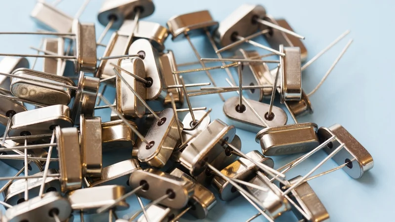
Crystal Oscillator: Fundamentals, Models, and Design Guidelines
A crystal oscillator is an electronic circuit that uses a quartz crystal to produce a precise and stable frequency reference. This article covers crystal operation, equivalent circuit models, resonance, load capacitance, oscillator topologies, stability, aging, and design practices.

15 Jun, 2026. 20 minutes read
Key Takeaways
The piezoelectric effect enables a quartz crystal to convert electrical energy into mechanical vibration and vice versa, forming the basis of crystal oscillator operation. AT-cut crystals provide an excellent balance of stability and cost, while SC-cut crystals offer superior aging and temperature performance.
A crystal resonator is modeled as a motional RLC network (Lm, Cm, and Rm) in parallel with a shunt capacitance (C0). This model explains the crystal's series and parallel resonant frequencies, as well as its exceptionally high quality factor (Q).
The most common oscillator circuit topologies are Pierce, Colpitts, and Clapp. Pierce oscillators are widely used with microcontrollers, while Colpitts and Clapp designs are often preferred in higher-frequency and RF applications.
Proper load capacitance matching is essential for frequency accuracy. The effective load capacitance is:
CL = (C1 × C2) / (C1 + C2) + Cstray
Even small capacitance mismatches can shift the oscillator frequency by several ppm.Drive level directly affects startup reliability, aging, and long-term stability. Excessive drive can damage the crystal resonator and accelerate frequency drift, while insufficient drive may prevent oscillation.
Standard crystal oscillators typically provide initial accuracy between ±10 ppm and ±50 ppm. For applications requiring tighter frequency stability, TCXO, VCXO, and OCXO solutions offer progressively higher performance, with OCXOs achieving stability as low as ±0.01 ppm.
Introduction
A crystal oscillator is an electronic circuit that uses a quartz crystal as a highly stable frequency reference to generate a precise periodic signal. Crystal oscillators are fundamental to modern electronics, providing the timing accuracy required for processors, communications equipment, industrial controls, and precision instrumentation. Their combination of excellent frequency stability, low jitter, and high quality factor makes them the preferred timing solution for applications ranging from low-power embedded devices to high-performance telecommunications systems.
Many electronic systems rely on multiple crystal-based timing sources. For example, a microcontroller may use a 32.768 kHz tuning-fork crystal to maintain a real-time clock (RTC) while using a separate 20 MHz crystal oscillator to generate the processor clock signal. Radio transmitters use crystal oscillators as local oscillator references, frequency synthesizers use them for frequency control, and test instruments depend on highly stable oscillators to maintain measurement accuracy. Compared with RC and LC oscillators, a crystal oscillator provides orders-of-magnitude better stability. While an RC oscillator can drift by several percent due to temperature variation, component tolerances, and power-supply fluctuations, a crystal oscillator typically maintains accuracy within tens of ppm (parts per million).
Crystal oscillators are available in several performance classes. A standard SPXO (simple packaged crystal oscillator) integrates a crystal resonator and amplifier into a single package and typically offers stability between ±20 ppm and ±100 ppm. A temperature-compensated crystal oscillator (TCXO) incorporates compensation circuitry to reduce frequency variation across temperature. An OCXO (oven-controlled crystal oscillator) actively regulates the crystal temperature to achieve exceptional stability, often below ±0.1 ppm. A voltage-controlled crystal oscillator (VCXO) uses a varactor diode to adjust its frequency, making it useful in synchronization systems and phase-locked loop (PLL) architectures. Together, these devices form the foundation of countless timing and synchronization applications.
The Piezoelectric Effect and Quartz Crystals
The operation of a crystal oscillator is based on the piezoelectric effect, a phenomenon in which certain crystalline materials generate electrical charge when mechanically stressed and deform when exposed to an electric field. Quartz, a crystalline form of silicon dioxide (SiO₂), exhibits both the direct and inverse piezoelectric effects, enabling it to convert electrical energy into mechanical vibration and mechanical vibration back into electrical energy.
When an alternating voltage is applied across the electrodes of a quartz crystal, the crystal physically expands and contracts. At specific resonant frequencies, these vibrations reinforce one another and create a stable mechanical resonance. Conversely, the vibrating crystal generates an electrical signal that can be amplified and sustained within an oscillator circuit. This electromechanical coupling allows a quartz crystal to function as an extremely selective crystal resonator with a quality factor far exceeding that of conventional LC networks.
Unlike ordinary resonant circuits built from capacitors and inductors, the resonant frequency of a quartz crystal is primarily determined by its physical dimensions and material properties. As a result, the oscillator frequency remains remarkably stable over time, making crystal oscillators ideal for applications that require accurate timing and low phase noise.
Recommended reading: What is a Sensor? An In-Depth Exploration and Comprehensive Guide to Engineering Principles and Applications
Why Quartz?
Although several materials exhibit piezoelectric properties, quartz remains the dominant material for crystal oscillators because of its unique combination of mechanical and electrical characteristics. Synthetic quartz can be grown with extremely high purity, exhibits low acoustic loss, and provides excellent long-term stability. These characteristics allow quartz crystals to achieve exceptionally high quality factors, often reaching tens of thousands or even hundreds of thousands in packaged devices. A high Q factor results in a very narrow resonance bandwidth, which improves frequency accuracy and reduces jitter and phase noise. These characteristics are particularly important in telecommunications equipment, RF systems, and high-speed digital applications where clock quality directly influences system performance.
The resonant frequency of a quartz crystal is largely determined by its thickness. By carefully controlling crystal dimensions during manufacturing, suppliers can produce crystal units covering a wide frequency range, from low-frequency 32.768 kHz devices used in RTC applications to high-frequency MHz oscillator designs used in communications and networking equipment. Quartz also exhibits excellent environmental stability. While external factors such as temperature, aging, and mechanical stress can affect performance, quartz generally provides better long-term frequency stability than alternative resonator technologies.
Crystal Cuts and Modes
The performance characteristics of a quartz crystal depend heavily on how the crystal is cut relative to its crystallographic axes. Different crystal cuts produce different vibration modes, temperature coefficients, and aging characteristics, making the cut an important design consideration. The most common crystal type is the AT-cut crystal. AT-cut crystals operate in a thickness-shear mode and are widely used across frequencies ranging from approximately 1 MHz to 250 MHz. Their frequency-temperature characteristic follows a cubic curve with an inflection point near 25°C, providing a good balance between stability, manufacturability, and cost. As a result, AT-cut crystals are commonly used in microcontrollers, communication devices, and general-purpose oscillator applications.
Applications requiring higher precision often use SC-cut crystals. These stress-compensated resonators employ a double-rotated crystal orientation that minimizes sensitivity to mechanical stress and environmental changes. SC-cut crystals exhibit exceptionally low aging rates and are commonly found in high-performance (Oven-Controlled Crystal Oscillator) OCXO designs where long-term stability is critical. Aging rates below 0.1 ppm per year are achievable under carefully controlled operating conditions.
BT-cut crystals represent another important category. These crystals exhibit different temperature characteristics and are frequently used in overtone applications requiring higher operating frequencies. Although less common than AT-cut devices, they remain important for specialized RF and frequency-control applications. At lower frequencies, tuning-fork crystals dominate. The familiar 32.768 kHz crystal used in watches, embedded systems, and RTC circuits operates in a flexural vibration mode rather than a thickness-shear mode. The frequency was specifically chosen because 32,768 equals 2¹⁵, allowing digital counters to divide the signal down to an accurate 1 Hz timing reference with minimal hardware. The selection of a crystal cut ultimately depends on the required frequency range, temperature range, stability requirements, and aging performance of the target application.
Operating Range and Overtones
Quartz crystals can operate at either their fundamental frequency or an overtone frequency. Fundamental-mode AT-cut crystals typically cover frequencies from approximately 1 MHz to 30 MHz. Above this range, the crystal must become increasingly thin to achieve higher resonant frequencies, making manufacturing more difficult and reducing mechanical robustness.
To overcome these limitations, designers often use overtone crystals. These devices are engineered to operate at odd harmonics of the fundamental resonance, commonly the third, fifth, or seventh overtone. Overtone operation enables crystal oscillators to achieve frequencies between 50 MHz and 200 MHz while maintaining practical crystal dimensions.
An overtone crystal contains multiple resonant modes. Consequently, the oscillator circuit must include frequency-selective elements that suppress unwanted resonances and encourage oscillation at the desired overtone. Depending on the design, an inductor, tuning capacitor, or resonant network may be incorporated to select the correct operating mode.
Because multiple resonant frequencies exist simultaneously, overtone oscillator design requires careful attention to startup behavior, gain margin, and frequency selection. Improper design can lead to oscillation at an unintended frequency, degraded spectral purity, increased jitter, and reduced frequency stability.
Crystal Equivalent Circuit and Resonance
Although a quartz crystal is a mechanical device, its behavior can be accurately represented using an electrical equivalent circuit. This model helps engineers analyze oscillator performance, predict frequency behavior, and design stable oscillator circuits. The equivalent circuit consists of a motional branch represented by a series combination of motional inductance (Lm), motional capacitance (Cm), and motional resistance (Rm). Together, these parameters model the mass, elasticity, and energy losses associated with the vibrating crystal.
Motional inductance (Lm) represents the inertia of the vibrating quartz structure. Motional capacitance (Cm) represents the crystal's mechanical compliance and is typically extremely small, often ranging from 2 fF to 20 fF for common MHz crystal resonators. Motional resistance (Rm) represents energy losses within the resonator and typically ranges from approximately 10 Ω to 150 Ω, depending on crystal construction and operating frequency. This motional branch is connected in parallel with a shunt capacitance, C0, which represents the static capacitance of the crystal electrodes, package, and mounting structure. Typical C0 values range from approximately 0.5 pF to 5 pF. The interaction between these elements determines the crystal's impedance characteristics and gives rise to its series and parallel resonances.
Series and Parallel Resonance
A quartz crystal exhibits both series and parallel resonance. These resonances arise from the interaction between the motional branch and the shunt capacitance, and they define the operating characteristics of the crystal oscillator. At the series resonance frequency, the reactances of Lm and Cm cancel one another, leaving only the motional resistance Rm. The series resonance frequency is:
fs = 1 / (2π√(LmCm))
At this frequency, the crystal exhibits minimum impedance and behaves almost like a pure resistor. Between the series and parallel resonances, the crystal behaves inductively. This region is particularly important because many oscillator circuits exploit this apparent inductive behavior to sustain oscillation. The parallel resonance frequency occurs when the motional branch resonates with the shunt capacitance C0. For cases where Cm is much smaller than C0, the parallel resonance frequency can be approximated by:
fp ≈ fs × [1 + Cm / (2C0)]
Because Cm is typically much smaller than C0, the difference between series and parallel resonance is usually only a few tens of ppm. Nevertheless, this small difference plays a significant role in determining the final oscillator frequency.
Load Resonance and Frequency Pulling
In practical applications, crystal oscillators rarely operate exactly at either series or parallel resonance. Instead, the crystal is connected to external capacitors that create a specific load capacitance, causing the operating frequency to shift slightly between the two resonant points.
In a typical Pierce oscillator, the effective load capacitance is determined by:
CL = (C1 × C2) / (C1 + C2) + Cstray
where C1 and C2 are the external load capacitors, and Cstray represents PCB, package, and parasitic capacitances.
Because crystal manufacturers specify a target load capacitance, selecting the correct capacitor values is essential for achieving the intended oscillator frequency. Even small load-capacitance errors can shift frequency by several ppm. Typical pulling sensitivities range from approximately –15 ppm/pF to –30 ppm/pF depending on crystal design. Frequency pulling is sometimes intentionally used for fine frequency control, particularly in VCXO and VCTCXO designs where a varactor modifies the effective load capacitance to adjust the output frequency.
Quality Factor and Stability
The quality factor, or Q, describes how efficiently a resonator stores energy relative to the energy it dissipates during each oscillation cycle. For the motional branch, the quality factor can be approximated as:
Q ≈ (1 / Rm) × √(Lm / Cm)
Standard AT-cut crystals routinely achieve Q values in the tens of thousands, while high-performance crystal resonators may exceed 100,000. Such high Q values are one of the primary reasons crystal oscillators exhibit excellent frequency stability and low phase noise. A high-Q resonator produces a narrow resonance bandwidth, making the oscillator less sensitive to external disturbances and reducing short-term frequency fluctuations. This characteristic directly contributes to lower jitter and improved spectral purity.
However, Q is not constant throughout the lifetime of a crystal. Excessive drive levels, contamination, mechanical stress, and aging mechanisms can gradually degrade resonator performance. For this reason, crystal oscillator design must balance startup margin, drive level, long-term reliability, and frequency stability to achieve optimal performance throughout the product lifecycle.
Oscillator Topologies
A quartz crystal does not generate oscillation on its own. To produce a continuous output signal, the crystal must be placed within an oscillator circuit that provides sufficient gain and feedback. The operation of all crystal oscillators is governed by the Barkhausen criterion, which states that oscillation occurs when the loop gain is greater than or equal to one and the total loop phase shift equals 0° or an integer multiple of 360°.
The exceptionally high Q factor of a crystal resonator ensures that only frequencies near its resonance satisfy these conditions. As a result, crystal oscillators provide far better frequency selectivity and stability than conventional LC oscillators. Among the many oscillator architectures available, Pierce, Colpitts, and Clapp oscillators remain the most widely used because they provide a reliable balance of startup performance, frequency accuracy, and implementation complexity.
Pierce Oscillator
The Pierce oscillator is the most common crystal oscillator topology and is integrated into countless microcontroller and logic devices. Its popularity stems from its simplicity: a single inverting amplifier, a feedback resistor, and two load capacitors are sufficient to create a stable oscillator. In a typical Pierce configuration, the crystal is connected between the input and output of an inverter. A feedback resistor (Rf) biases the inverter into its linear operating region, while capacitors C1 and C2 establish the load capacitance seen by the crystal. A series resistor (Rs) is often added to control crystal drive level and improve long-term reliability.
The effective load capacitance is:
CL = (C1 × C2) / (C1 + C2) + Cstray
where Cstray includes package capacitance, PCB parasitics, and the input/output capacitance of the active device.
Because the Pierce oscillator presents a relatively predictable load to the crystal, it is the preferred choice for low-power embedded systems, RTC circuits, and general-purpose clock generation. Most modern microcontrollers include a dedicated crystal oscillator stage optimized for this topology.
Pierce Oscillator Design Considerations
Capacitor selection directly affects oscillator frequency and startup margin. In most designs, C1 and C2 are chosen to be equal or nearly equal, with values typically ranging from 10 pF to 22 pF for standard MHz crystal oscillators. Designers must also account for stray capacitance introduced by PCB traces, device packaging, and the oscillator input stage. The feedback resistor Rf establishes the inverter's DC operating point. Typical values range from approximately 1 MΩ for lower-frequency crystals to several hundred kilohms for higher-frequency designs.
The series resistor Rs limits drive current through the crystal and helps prevent overdriving. This resistor becomes particularly important when using high-speed CMOS devices, whose output stages can easily exceed the crystal's maximum drive specification. Startup performance is another critical consideration. The oscillator must generate sufficient negative resistance to overcome the crystal's motional resistance. As a rule of thumb, the available negative resistance should be at least four to ten times greater than the crystal's equivalent series resistance to ensure reliable startup under worst-case operating conditions.
Colpitts Oscillator
The Colpitts oscillator employs a transistor or FET amplifier combined with a capacitive feedback divider. Unlike the Pierce oscillator, which relies on a digital inverter, the Colpitts architecture gives designers more direct control over gain, drive level, and load impedance. In a crystal-based Colpitts oscillator, the crystal replaces the inductive element normally found in a conventional LC design. The crystal operates within its inductive region between series and parallel resonance, allowing it to sustain oscillation while providing excellent frequency selectivity.
Because designers have greater control over circuit parameters, Colpitts oscillators are frequently used in RF systems, communications equipment, and higher-frequency MHz oscillator applications. Frequencies well above 100 MHz can be achieved through overtone operation while maintaining excellent stability and relatively low jitter.
The tradeoff is increased design complexity. Unlike the Pierce oscillator, the Colpitts topology requires careful biasing, gain control, and impedance matching to ensure reliable operation across temperature and manufacturing tolerances.
Clapp Oscillator
The Clapp oscillator is a refinement of the Colpitts design that introduces an additional capacitor in series with the crystal. This capacitor dominates the total resonant capacitance and reduces the influence of variations in the feedback divider network. By making the oscillation frequency less sensitive to transistor capacitance and parasitic effects, the Clapp topology generally provides better frequency stability than a conventional Colpitts oscillator. This characteristic makes it attractive for precision RF applications, frequency synthesizers, and tunable oscillator systems. The Clapp architecture is also commonly used when implementing voltage controlled crystal oscillator (VCXO) and VCTCXO designs, where a variable capacitance element adjusts the output frequency over a limited range. In these applications, careful capacitor selection helps maintain stability while allowing controlled frequency pulling.
Comparing Pierce, Colpitts, and Clapp Oscillators
Although these topologies appear different, they all operate according to the same fundamental principle: an active device supplies gain while the crystal determines the oscillation frequency. Each topology generates an effective negative resistance that compensates for losses within the crystal resonator. The Pierce oscillator remains the preferred choice for microcontrollers, low-power electronics, and clock-generation circuits because of its simplicity and ease of implementation. Colpitts oscillators provide greater flexibility for RF and higher-frequency applications, while Clapp oscillators are often selected when improved stability or tunability is required. From a practical design perspective, the choice usually depends on frequency range, power consumption, startup requirements, and the degree of frequency control required by the application.
Load Capacitance Matching
Crystal manufacturers specify a target load capacitance for which the crystal frequency is calibrated. Common values include 12.5 pF, 16 pF, 18 pF, and 20 pF.
In a Pierce oscillator, the effective load capacitance is:
CL = (C1 × C2) / (C1 + C2) + Cstray
where C1 and C2 are the external capacitors, and Cstray includes package, device, and PCB parasitic capacitances.
For example, if a crystal is specified for an 18 pF load capacitance and the estimated stray capacitance is 5 pF, designers typically select capacitor values near 22 pF to 27 pF to achieve the desired operating point.
Accurate load-capacitance matching is essential because frequency shifts occur whenever the actual load differs from the manufacturer's specification. Typical trim sensitivity ranges from approximately –15 ppm/pF to –30 ppm/pF. Consequently, a mismatch of only 1 pF can introduce measurable frequency error. Applications requiring extremely high accuracy often compensate for these errors using firmware calibration, a TCXO, or an OCXO.
Component Selection Considerations
Load capacitors should generally use NP0/C0G dielectric materials because of their low loss and excellent temperature stability. Large differences between C1 and C2 should be avoided, as asymmetrical loading can increase crystal stress, degrade startup margin, and potentially excite unwanted vibration modes.
Proper PCB design is equally important. Long traces increase parasitic capacitance and susceptibility to electromagnetic interference (EMI), both of which can influence oscillator frequency and increase phase noise.
Drive Level
Quartz crystals are precision mechanical structures, and excessive drive can permanently damage them. The drive level represents the power dissipated within the crystal and is typically specified in microwatts or milliwatts.
Most standard AT-cut crystal oscillators operate at drive levels between 10 µW and 100 µW, although some devices can tolerate higher levels. Excessive drive increases mechanical stress, accelerates aging, and can shift the oscillator frequency over time. In extreme cases, it may cause electrode degradation or physical fracture of the crystal. Insufficient drive presents a different problem. If the available loop gain is too low, the oscillator may fail to start or exhibit unreliable startup behavior under temperature extremes.
The series resistor Rs provides a simple method of controlling crystal drive. Increasing Rs reduces current through the crystal, lowering power dissipation and improving long-term reliability. Watch crystals operating at 32.768 kHz are particularly sensitive because their maximum drive level may be only a few microwatts. The feedback resistor Rf serves a different purpose. Rather than limiting current, it biases the active device into its linear operating region and enables oscillation to begin when power is applied.
Measuring Drive Level
Drive level can be estimated by measuring the RMS voltage across the crystal and calculating the dissipated power:
P = Vrms² / (2Rm)
where Rm is the crystal's motional resistance.
For more accurate measurements, engineers often use current probes or specialized test fixtures that allow the crystal current to be measured directly. High-bandwidth oscilloscopes are commonly used to verify startup behavior, waveform integrity, and frequency stability during oscillator validation.
Frequency Tolerance and Stability
The performance of a crystal oscillator is determined not only by its nominal frequency but also by how accurately that frequency is maintained over time and under changing operating conditions. Engineers typically evaluate oscillator performance using four key metrics: initial tolerance, temperature stability, voltage sensitivity, and aging. Together, these parameters determine whether a timing source is suitable for applications ranging from a low-power microcontroller clock to a high-precision telecommunications reference.
Initial Frequency Tolerance
Initial frequency tolerance describes how closely a crystal's actual frequency matches its specified value immediately after manufacturing, typically measured at 25°C. For example, a 20 MHz crystal specified at ±20 ppm may operate anywhere between 19.9996 MHz and 20.0004 MHz under reference conditions.
Standard AT-cut quartz crystal devices are commonly available with initial tolerances ranging from ±10 ppm to ±100 ppm, although tighter specifications can be achieved through additional calibration and screening. Initial tolerance represents the starting point for overall frequency error; temperature effects, aging, and load-capacitance variations further contribute to total system accuracy.
Temperature Stability
Temperature is often the largest source of frequency variation in a crystal oscillator. As the crystal expands and contracts with changing temperature, its mechanical properties shift slightly, altering its resonant frequencies and therefore the oscillator frequency. Standard AT-cut crystals typically exhibit frequency variation between ±20 ppm and ±100 ppm across an industrial temperature range of –40°C to +85°C. Their frequency-temperature response follows a cubic curve, with the frequency crossing nominal near room temperature and deviating progressively at temperature extremes.
Applications requiring tighter frequency stability often use a temperature-compensated crystal oscillator (TCXO) or an OCXO. A TCXO continuously corrects temperature-induced drift using compensation circuitry and a temperature sensor, while an OCXO maintains the crystal at a fixed elevated temperature to virtually eliminate environmental fluctuations.
Recommended reading: RTD vs Thermocouple: A Comprehensive Guide for Engineers
Voltage and Load Sensitivity
Although temperature dominates most crystal frequency errors, changes in the power supply and load capacitance can also influence oscillator performance. A crystal oscillator is calibrated for a specific load capacitance. Deviations from the specified load shift the operating frequency, a phenomenon known as frequency pulling. Likewise, supply-voltage variations can alter the behavior of the active amplifier stage, introducing small changes in oscillator frequency.
For most embedded applications, these effects are negligible. However, systems requiring sub-ppm accuracy—such as precision instrumentation, frequency standards, and telecommunications equipment—must carefully control both load conditions and supply regulation.
Aging and Long-Term Stability
Aging refers to the gradual change in oscillator frequency over time. Unlike temperature-induced drift, which is reversible, aging causes permanent shifts in frequency due to physical changes within the crystal structure and package.
Common aging mechanisms include:
Stress relaxation within the crystal mount
Surface contamination
Electrode migration
Material outgassing
Plating wear
Mechanical shock and vibration
Most standard AT-cut crystal oscillators exhibit aging rates between ±1 ppm and ±5 ppm per year. The largest frequency shifts typically occur during the first year of operation, after which the aging rate decreases significantly. SC-cut resonators used in high-performance OCXO designs achieve substantially lower aging rates, often below 0.1 ppm per year. These devices are commonly used in frequency standards, precision measurement systems, and critical timing infrastructure. Drive level also influences aging. Excessive crystal drive accelerates mechanical stress and electrode wear, while carefully controlled drive levels improve long-term stability.
Oscillator Stability Classes
The required stability level depends heavily on the application. While a general-purpose embedded system may tolerate tens of ppm of drift, communications equipment and frequency references often require much tighter control.
Oscillator Type | Initial Tolerance | Temperature Stability | Aging Rate | Typical Applications |
Bare crystal oscillator | ±10 to ±50 ppm | ±20 to ±100 ppm | ±1 to ±5 ppm/year | Embedded systems, general clock generation |
SPXO | ±20 to ±100 ppm | ±20 to ±100 ppm | ±1 to ±5 ppm/year | Consumer electronics |
TCXO | ±0.5 to ±5 ppm | ±0.5 to ±5 ppm | ~±1 ppm/year | GNSS, wireless communications, industrial control |
VCXO | ±20 ppm typical | ±10 to ±50 ppm | ~±1 ppm/year | PLL synchronization systems |
OCXO | ±0.2 to ±2 ppm | ±0.01 to ±0.1 ppm | <0.1 ppm/year | Frequency standards, telecommunications, test equipment |
The selection of an oscillator technology represents a tradeoff between accuracy, power consumption, size, startup time, and cost. While TCXOs and OCXOs provide exceptional performance, standard crystal oscillators remain the preferred choice for most applications because they deliver excellent stability at low cost and low power.
Recommended reading: Selecting the Best Power Solution for Radio Frequency Signal Chain Phase Noise Performance
Selecting a Quartz Crystal
Selecting the right quartz crystal involves more than choosing an operating frequency. The crystal must be compatible with the oscillator circuit, environmental requirements, and long-term stability objectives of the application. The first consideration is frequency. Standard AT-cut crystals cover approximately 1 MHz to 30 MHz in their fundamental mode. Higher-frequency applications often require overtone crystals or alternative resonator technologies.
The specified load capacitance must also match the capabilities of the oscillator circuit. Common values include 12.5 pF, 16 pF, 18 pF, and 20 pF. Designers should include all sources of stray capacitance, including package effects and PCB parasitics, when calculating the effective load. Equivalent series resistance (ESR) is another critical parameter. Lower ESR generally improves startup reliability and reduces phase noise. Most microcontroller manufacturers specify a maximum allowable ESR to ensure reliable oscillator startup.
Drive-level ratings should also be verified. A crystal operating above its specified drive level may experience increased aging, reduced frequency stability, and eventual failure. Package selection affects both performance and manufacturability. Common options include HC-49 through-hole packages, surface-mount crystal units, and miniature tuning-fork packages used in low-power RTC applications. Smaller packages often exhibit higher ESR and lower drive capability, making careful component selection essential.
PCB Layout and Implementation Guidelines
Even a carefully selected crystal can perform poorly if the surrounding PCB layout is not optimized. Because oscillator nodes are sensitive analog circuits, parasitic capacitance, electromagnetic interference, and grounding issues can significantly degrade performance. Crystal traces should be kept as short and symmetrical as possible. Long traces increase parasitic inductance and capacitance, alter the effective load seen by the crystal, and increase susceptibility to EMI.
Load capacitors should be placed close to the crystal and connected to a low-impedance ground. Maintaining symmetrical routing helps ensure balanced loading and reduces the risk of exciting unwanted vibration modes. High-speed digital traces, switching regulators, and power electronics should be routed away from the crystal network whenever possible. Noise coupled into the oscillator can increase jitter, degrade phase noise, and in severe cases prevent reliable startup.
Ground shielding techniques, such as guard rings and local copper pours, can further improve immunity to interference. However, excessive copper near crystal pins may increase parasitic capacitance, so layout optimization often requires balancing shielding and loading effects. Finally, designers should follow the crystal manufacturer's recommendations for capacitor values, resistor selection, drive level, and startup margin. Even small deviations from recommended operating conditions can affect long-term oscillator performance.
Recommended reading: PCB Layout: A Comprehensive Guide
Conclusion
The quartz crystal remains one of the most important timing elements in modern electronics. By leveraging the piezoelectric properties of quartz, a crystal oscillator can provide exceptional frequency accuracy, low jitter, and long-term stability while consuming relatively little power. The crystal's equivalent circuit—consisting of a motional inductance, motional capacitance, motional resistance, and shunt capacitance—explains the existence of both series and parallel resonant frequencies, which form the basis of oscillator operation. Understanding these electrical models allows engineers to predict oscillator behavior, calculate load conditions, and optimize circuit performance.
Among the available oscillator topologies, the Pierce oscillator remains the preferred choice for most microcontroller, embedded, and low-power applications because of its simplicity and ease of implementation. Colpitts and Clapp oscillators provide additional flexibility for higher-frequency MHz oscillator designs, overtone operation, and tunable architectures such as VCXO and VCTCXO systems. Achieving reliable oscillator performance requires more than selecting the correct crystal. Load-capacitance matching, proper PCB layout, startup margin verification, impedance control, drive-level management, and EMI mitigation all influence the final oscillator frequency and long-term reliability.
For many applications, a standard AT-cut crystal oscillator delivering ±20 ppm to ±100 ppm stability is sufficient. Systems requiring tighter frequency control can benefit from a TCXO, while applications demanding the highest levels of accuracy and long-term frequency stability often require an OCXO. By understanding these tradeoffs and applying sound design practices, engineers can build oscillator circuits that maintain accurate timing for years of operation.
Frequently Asked Questions
What is a crystal oscillator and how does it work?
A crystal oscillator is an electronic circuit that uses a quartz crystal as a highly selective resonator to generate a stable periodic signal. The crystal's piezoelectric properties convert electrical energy into mechanical vibration and back into an electrical signal. When combined with an amplifier and feedback network, the circuit oscillates at a predictable frequency determined by the crystal's physical characteristics.
What is the difference between a crystal resonator and a crystal oscillator?
A crystal resonator is the passive quartz component that provides frequency selectivity. A crystal oscillator includes the resonator plus the amplifier, feedback network, and supporting components required to generate a usable clock signal. In other words, the crystal is one part of the complete oscillator circuit.
Why is 32.768 kHz commonly used in clocks and RTC circuits?
The frequency 32.768 kHz equals 2¹⁵ Hz. This allows simple digital divider circuits to repeatedly divide the signal by two until a precise 1 Hz output is obtained. As a result, 32.768 kHz crystals are widely used in RTC modules, watches, battery-powered devices, and low-power embedded systems.
What is the difference between TCXO, VCXO, and OCXO?
A TCXO uses temperature compensation circuitry to reduce frequency drift across temperature changes. A VCXO allows limited adjustment of the oscillator frequency through a control voltage and is commonly used in PLL systems. An OCXO maintains the crystal at a controlled temperature, providing the highest stability and lowest aging of the three technologies.
How does load capacitance affect oscillator frequency?
The operating frequency of a crystal oscillator depends on the load capacitance seen by the crystal. If the actual load capacitance differs from the manufacturer's specified value, the oscillator frequency shifts. Even a 1 pF mismatch can produce measurable errors, often in the range of several ppm.
What causes crystal oscillators to age?
Aging results from gradual physical changes within the crystal and its package, including stress relaxation, contamination, electrode migration, and material outgassing. Most frequency drift occurs during the first year of operation and then slows over time. Proper drive-level control and high-quality crystal construction help minimize aging effects.
When should I choose an OCXO instead of a TCXO?
A TCXO is typically sufficient when frequency accuracy requirements are within a few ppm across the operating temperature range. An OCXO becomes necessary when sub-ppm stability, ultra-low jitter, extremely low aging, or metrology-grade performance is required, such as in telecommunications networks, frequency standards, and laboratory instrumentation.
Can any quartz crystal be connected directly to a microcontroller?
No. Every microcontroller oscillator stage supports a specific range of crystal frequencies, load capacitances, and equivalent series resistance (ESR) values. Designers should always verify compatibility with the manufacturer's datasheet and follow recommended values for capacitors, resistors, and PCB layout to ensure reliable startup and stable operation.
References
[1] R. Matthys, Crystal Oscillator Circuits, New York, NY, USA: Wiley, 1983.
[2] E. A. Gerber and A. Ballato, “Precision Frequency Control, Volume 1: Crystal Oscillators,” in Precision Frequency Control, New York, NY, USA: Academic Press, 1985.
[3] J. R. Vig, “Quartz Crystal Resonators and Oscillators for Frequency Control and Timing Applications—A Tutorial,” U.S. Army Communications-Electronics Research, Development and Engineering Center (CERDEC), Fort Monmouth, NJ, USA, Technical Report SLCET-TR-92-1, 2004.
[4] Analog Devices, “Specifying Quartz Crystals,” Nov. 19, 2001. Available: https://www.analog.com/en/resources/technical-articles/specifying-quartz-crystals.html
[5] S. Raza, “Understanding the Basics of the Pierce Oscillator,” Abracon LLC, Application Note. Available: Abracon Pierce Oscillator Fundamentals
[6] A. Ballato, “Piezoelectricity: Old Effect, New Thrusts,” IEEE Transactions on Ultrasonics, Ferroelectrics, and Frequency Control, vol. 42, no. 5, pp. 916–926, Sept. 1995.
[7] J. Vig and Y. Kim, “Noise in Microelectromechanical System Resonators,” IEEE Transactions on Ultrasonics, Ferroelectrics, and Frequency Control, vol. 46, no. 6, pp. 1558–1565, Nov. 1999.
in this article
1. Key Takeaways2. Introduction3. The Piezoelectric Effect and Quartz Crystals4. Oscillator Topologies5. Comparing Pierce, Colpitts, and Clapp Oscillators6. Load Capacitance Matching7. Frequency Tolerance and Stability8. Selecting a Quartz Crystal9. PCB Layout and Implementation Guidelines10. Frequently Asked Questions11. References