What is SMT: A Comprehensive Guide to Surface Mount Technology
Surface Mount Technology (SMT) revolutionized electronics manufacturing by enabling smaller, faster, and more efficient circuit designs. This guide delves into the core principles of SMT, explores its cutting-edge advancements, and addresses the challenges in implementing this technology.

04 Feb, 2025. 12 minutes read
Introduction
Surface Mount Technology (SMT) is a pivotal innovation in modern electronics, enabling the development of smaller, faster, and more efficient devices. SMT has streamlined manufacturing processes by allowing components to be mounted directly onto the surface of printed circuit boards (PCBs) and opened the door to advanced designs. It has contributed to miniaturized electronics, paving the way for portable devices after making them more space-efficient and compact.
As a result, SMT is integral to modern industries ranging from consumer electronics to aerospace, providing engineers with the tools to create high-performance, compact systems. This article explores SMT's principles, advancements, and challenges, highlighting its transformative role in electronics engineering.
Understanding Surface Mount Technology
What is Surface Mount Technology?
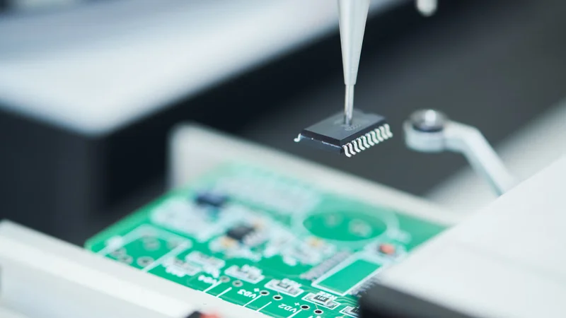
Surface Mount Technology (SMT) is a method in electronics manufacturing where components are mounted directly onto the surface of printed circuit boards (PCBs) instead of using wire leads that pass through holes. This approach allows for compact designs, faster assembly, and improved electrical performance.
Applications of SMT
Mobile phones and tablets
Wearable devices
Automotive control systems
High-frequency telecommunications equipment
Comparison: SMT vs. Through-Hole Technology
Size: SMT components are smaller, allowing for compact PCB designs, whereas through-hole components require more space.
Design Flexibility: SMT offers more design flexibility because there is no need to drill accurately placed holes. However, it also requires advanced PCB design skills and assembly techniques.
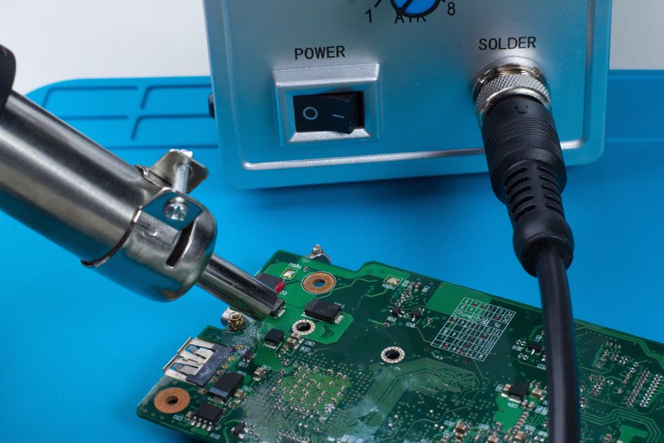
Assembly Speed: SMT supports automation with pick-and-place machines, whereas through-hole requires manual soldering for complex designs.
Durability: SMT is ideal for lightweight, high-performance devices, while through-hole offers superior mechanical strength for heavy components.
Cost: SMT is less labor-intensive as compared to through-hole technology as there is no drilling, lead insertion, etc. required.
Thermal Efficiency: SMT enhances heat dissipation due to direct contact with PCB, but also leads to thermal stress. Through-hole technology is better suited for high-power applications as it can handle higher thermal loads.
Suggested Reading: Through Hole vs Surface Mount: Unveiling the Optimal PCB Assembly Technique
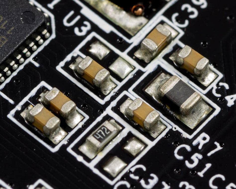
Key Components Used in SMT
SMT utilizes a range of specialized components designed to optimize performance and reliability in electronic circuits. Below are some of the most commonly used components and their roles:
Resistors: Regulate current flow and voltage levels.
Capacitors: Store and release electrical energy, crucial for stabilizing voltage and filtering noise.
Inductors: Store energy in magnetic fields, commonly used in power supplies and RF applications.
Diodes: Allow current to flow in one direction and protect circuits from voltage spikes.
Integrated Circuits (ICs): Combine multiple electronic functions into a compact package, such as microprocessors and memory chips.
Transistors: Act as switches or amplifiers in electronic circuits.
Package Type | Size (mm) | Application | Complexity |
0402 (metric 1005) | 1.0 x 0.5 | High-density PCBs | Low to Moderate |
0603 (metric 1608) | 1.6 x 0.8 | General-purpose circuits | Moderate |
QFN (Quad Flat No-Lead) | Varies | High-performance ICs | High |
BGA (Ball Grid Array) | Varies | Microprocessors, GPUs | Very High |
This combination of components allows SMT to deliver efficient, compact, and versatile designs suitable for modern electronics.
Suggested Reading: Circuit Board Components Identification: A Comprehensive Guide
How Does SMT Work?
Application of Solder Paste: A stencil printer applies solder paste to designated areas on the PCB where components will be mounted. The paste consists of solder and flux, ensuring proper adhesion.
Component Placement: A pick-and-place machine accurately positions components onto the PCB. These machines use suction nozzles, high-speed cameras, and precise X-Y coordinate control for efficiency.
Reflow Soldering: The PCB is passed through a reflow oven, where it is gradually heated to melt the solder paste, forming a secure electrical and mechanical connection between the components and the board.
Inspection and Testing: Automated Optical Inspection (AOI) systems verify solder joint quality and component placement. X-ray inspection may also be used for multi-layer boards or BGAs.
Types of SMT and How to Pick the Right One
Type I SMT: The Foundation
Type I SMT represents the most basic approach to surface mount assembly. The defining characteristic is the exclusive use of Surface Mount Devices (SMDs). No through-hole components are present. SMDs can be placed on either one or both sides of the PCB.
Single-Sided Assembly: In this variation, all SMDs are placed on just one side of the board. This is often the simplest and most cost-effective approach, suitable for less complex circuits. The assembly process typically involves applying solder paste, placing the components, and then reflow soldering.
Double-Sided Assembly: Here, SMDs are placed on both sides of the PCB. This increases component density and allows for more complex circuit designs. Double-sided assembly often involves multiple reflow soldering passes. One side is populated and soldered, then the board is flipped, and the process is repeated for the other side. Sometimes, adhesive is used to hold components on the underside during the second soldering pass.
Type I SMT is often chosen for its simplicity and lower manufacturing costs, making it suitable for applications where component density and circuit complexity are not paramount.
Type II SMT: The Mixed Technology Approach
Type II SMT introduces a mixed technology approach, combining both through-hole and surface mount components on the same board. Typically, through-hole and SMT components are placed on the primary side of the PCB, while only SMT components are placed on the secondary side.
Combining Technologies: This approach allows designers to leverage the advantages of both through-hole and surface mount technologies. Through-hole components might be chosen for larger or heavier components, connectors, or components that require strong mechanical connections. SMT components provide the density and performance benefits discussed earlier.
Increased Complexity: Type II assembly is more complex than Type I. It often requires multiple soldering processes. The through-hole components are typically wave soldered, while the SMT components are reflow-soldered. Careful process control is essential to ensure the quality of both types of solder joints.
Type II SMT is often used in applications where a mix of component types is necessary, such as in industrial control systems, power supplies, and some consumer electronics.
Type III SMT: A Variation on Mixed Technology
Type III SMT is another form of mixed technology assembly, similar to Type II in that it uses both through-hole and surface mount components and populates both sides of the PCB. However, the key difference lies in the component placement. In Type III, only through-hole components are mounted on the primary side of the PCB. The secondary side, as in Type II, uses only SMT components.
Specific Component Distribution: This approach might be chosen for specific design requirements or to accommodate particular component types. It can offer a different way to balance component density and mechanical strength compared to Type II.
Similar Manufacturing Challenges: Like Type II, Type III assembly is more complex than Type I and requires careful process control, including wave soldering for through-hole components and reflow soldering for SMT components.
Type III SMT might be used in applications where the placement of through-hole components on the primary side offers some advantage, such as for mechanical support or specific connector placement.
Choosing the Right SMT Type
The choice of SMT type depends on several factors, including:
Circuit complexity: More complex circuits often require higher component density, pushing designers toward double-sided Type I or mixed technology (Type II or III).
Component types: The presence of through-hole components necessitates Type II or III.
Cost considerations: Type I is generally the most cost-effective, while Type II and III involve more complex processes and higher costs.
Production volume: High-volume production often favors automated SMT processes, regardless of the specific type.
Understanding the characteristics of each SMT type allows manufacturers to select the most appropriate approach for their specific product and manufacturing requirements.
Innovations Driving SMT Forward
Automation in SMT Assembly
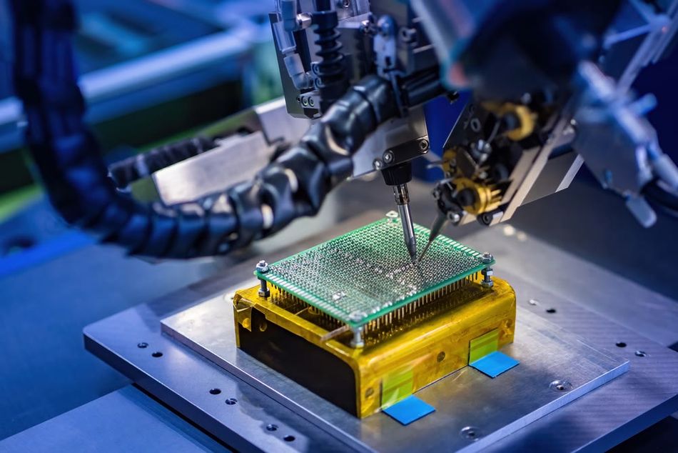
Modern SMT manufacturing relies heavily on advanced automation systems to enhance precision and efficiency. Automation reduces labor costs by replacing manual tasks with high-speed robotic systems, while also scaling production capabilities to meet the demands of mass manufacturing. These systems enable consistent quality control, streamline workflows, and minimize operational downtime, making large-scale production more cost-effective. Examples of automated systems include:
Pick-and-Place Machines: High-speed pick and place robotic systems can place components on PCBs. These machine precisely and swiftly places surface mount components onto printed circuit boards (PCBs), ensuring accuracy and efficiency in assembly.
Reflow Ovens: Temperature-controlled machines that ensure uniform soldering of components. Reflow ovens use precisely controlled heating to melt the solder paste, creating reliable electrical connections that bond the surface mount components to the PCB.
Stencil Printers: These are automated equipment for precise application of solder paste. Stencil printers play a vital role in PCB assembly by precisely and evenly applying solder paste. This accurate solder deposition is essential for the successful placement and soldering of surface mount components.
Solder Paste Inspection Systems: SPI systems ensure the quality of the solder paste and uniform deposition before the component placement. It reduces production defects and improves efficiency.
Automated Optical Inspection (AOI) Systems: High-resolution imaging systems to inspect solder joints and component alignment.
Suggested Reading: What is AOI (Automated Optical Inspection): A Comprehensive Guide
Depaneling Equipment: This equipment is used to separate multiple PCB panels after the assembly process. It uses precise separation techniques to ensure clean and breakage-free separation of boards.
Benefits of Automation in SMT
Surface Mount Technology (SMT) has revolutionized electronics manufacturing, offering a multitude of benefits that have made it the dominant assembly method.
Miniaturization and Increased Density
The smaller size of Surface Mount Devices (SMDs) compared to traditional through-hole components allows for a significantly higher component density on printed circuit boards (PCBs). This miniaturization enables the creation of more compact and complex circuit designs, packing more functionality into smaller spaces.
Enhanced Electrical Performance
SMT's shorter interconnection lengths improve electrical performance, particularly at high frequencies. Reduced signal distortion and improved signal integrity contribute to faster and more reliable circuit operation.
Cost-Effectiveness and Efficiency
The automated nature of SMT assembly significantly lowers labor costs and increases production efficiency. This automation, coupled with higher throughput, makes SMT a highly cost-effective solution for mass production of electronic devices. It also reduces human error, contributing to higher product quality and improved consistency across production batches.
Improved Reliability
SMT solder joints are generally more reliable than through-hole connections. They are less susceptible to mechanical stress and thermal cycling failures, leading to more robust and durable electronic products.
Versatility and Component Range
SMT's versatility is a key advantage. It can accommodate a wide range of component types, from basic resistors and capacitors to complex fine-pitch microprocessors. This adaptability makes SMT suitable for diverse electronic applications, from simple circuits to highly sophisticated electronic systems.
Miniaturization Trends in SMT
Material innovations play a crucial role in enabling the miniaturization of electronic devices, driving advancements in Surface Mount Technology (SMT). Industries such as consumer electronics, medical devices, and aerospace benefit significantly from these trends, as they require compact, lightweight, and high-performance solutions. These innovations include:
High-Density Substrates: Advanced materials like Liquid Crystal Polymer (LCP) and Polyimide allow for thinner and more flexible PCBs, accommodating dense component layouts.
Fine-Pitch Components: Developments in semiconductor packaging, such as micro-BGA and wafer-level packages, contribute to reducing component size.
Advanced Solder Materials: Lead-free, low-temperature solder alloys provide robust connections while minimizing thermal stress on miniature components.
Suggested Reading: Types of Solder: A Comprehensive Guide for Engineering Professionals
Challenges in Miniaturization
Thermal Dissipation: Managing heat in densely packed PCBs without compromising performance.
Assembly Precision: Achieving accurate placement and soldering of micro-scale components.
Inspection Complexity: Ensuring quality control for components with increasingly smaller geometries.
Material Costs: High-performance materials often come at a premium, affecting cost efficiency in production.
High-Density Interconnects (HDI) and Advanced PCBs
High-Density Interconnects (HDI) PCBs are advanced circuit boards designed to accommodate complex, high-performance applications. They integrate seamlessly with Surface Mount Technology (SMT) processes, enabling efficient use of space and improved signal integrity.
Technical Details of HDI PCBs
Microvias: Allow connections between multiple layers, significantly increasing density without enlarging the PCB footprint.
Buried and Blind Vias: Enhance layer interconnectivity while preserving surface area for components.
Material Selection: High-performance laminates like FR4 High-Tg and polyimide are used to handle thermal and mechanical stresses.
Signal Integrity: Improved layout capabilities reduce crosstalk and electromagnetic interference (EMI), ensuring reliable operation at high frequencies.
Feature | Traditional PCBs | HDI PCBs |
Layer Count | Low to Moderate | High |
Via Type | Through-hole | Microvias, Blind/Buried |
Density | Standard | High |
Signal Integrity | Moderate | Excellent |
Applications | General Electronics | Advanced, High-Speed |
Applications of Solder Mount Technology
Surface Mount Technology (SMT) is a cornerstone of modern electronics manufacturing, enabling the creation of smaller, more powerful, and more reliable devices across diverse industries. Its impact is particularly evident in the following sectors:
Consumer Electronics: SMT is ubiquitous in consumer electronics, from mobile phones, tablets, and laptops to wearable devices and smart home appliances. SMT's ability to create compact designs is crucial for the sleek and portable nature of these products. High component density allows for increased functionality within a limited space.
Automotive Electronics: The automotive industry relies heavily on SMT for a wide range of applications. Engine control units (ECUs), infotainment systems, Advanced Driver-Assistance Systems (ADAS), and even lighting systems utilize SMT to achieve the necessary performance, reliability, and small form factor required in demanding automotive environments. The ability to withstand harsh conditions is also a critical factor.
Medical Devices: In the medical field, SMT is essential for critical devices like pacemakers, defibrillators, hearing aids, and diagnostic equipment. Miniaturization is paramount for implantable devices, while reliability is crucial for all medical applications. High-quality manufacturing processes are essential to meet stringent medical device standards.
Industrial Equipment: SMT components are integral to industrial automation systems, robotics, control panels, and power electronics. The use of SMT contributes to improved efficiency, productivity, and the overall performance of industrial equipment. The robustness and reliability of SMT components are crucial in often harsh industrial settings.
Telecommunications: SMT plays a vital role in telecommunications infrastructure. Base stations, routers, switches, and optical networking equipment all rely on SMT to achieve the high density, high-speed performance, and reliability necessary for modern communication networks. The compact size of SMT components allows for dense packaging of circuitry within telecommunications equipment.
Differences Between SMT and SMD
Surface Mount Device (SMD) and Surface Mount Technology (SMT) are related terms that are sometimes used interchangeably, but they have distinct meanings. SMD refers to the electronic components themselves—like capacitors, resistors, and integrated circuits—that are designed to be surface mounted on a printed circuit board (PCB). SMT, on the other hand, describes the process of attaching those SMDs to the PCB. Essentially, SMD represents the components, while SMT is the method used to assemble them onto the board.
Suggested Reading: SMD Package Types and Sizes: A Comprehensive Guide for Engineers
Challenges Engineers Face with SMT
Thermal Management Issues
Thermal challenges in SMT designs arise from the compact nature of components and the increasing power density in modern electronics. Efficient heat dissipation is critical to maintaining component reliability and preventing performance degradation.
Heat Sinks: Dissipate heat away from critical components by increasing surface area.
Thermal Vias: Conduct heat through PCB layers to distribute it evenly.
Heat Spreader Layers: Embedded metal layers within the PCB to aid in thermal management.
Thermal Interface Materials (TIMs): Improve heat conduction between components and heat sinks.
Active Cooling Systems: Incorporate fans or liquid cooling for high-power applications.
Design Optimization: Proper layout of high-power components to avoid heat concentration.
Precision Requirements
Precision in SMT assembly lines depends heavily on the capabilities of advanced equipment designed for high accuracy. Key specifications include:
Pick-and-Place Machines: Feature placement accuracy of up to ±10 microns, ensuring precise alignment of components.
Stencil Printers: Provide alignment accuracy within ±25 microns to apply solder paste uniformly.
Reflow Ovens: Utilize precise temperature profiling, maintaining variations within ±2°C to prevent thermal stress.
Inspection Systems: High-resolution AOI systems capable of detecting defects as small as 10 microns.
Cost Considerations
Small-Scale Production:
Higher per-unit costs due to limited economies of scale.
Frequent retooling and setup adjustments for diverse product runs.
Dependency on semi-automated systems, increasing labor expenses.
Large-Scale Production:
Reduced per-unit costs through high-volume efficiency.
High initial capital investment in advanced automated machinery.
Lower operational costs due to streamlined workflows and reduced manual intervention.
Conclusion
Surface Mount Technology (SMT) has redefined electronics manufacturing by enabling compact designs, high-speed assembly, and superior performance. For instance, in the medical industry, SMT has facilitated the creation of miniature diagnostic devices, enhancing portability and accessibility for patients.
Its integration into modern engineering practices underpins advancements in diverse industries such as telecommunications, automotive, and consumer electronics. As a transformative technology, SMT continues to evolve, addressing challenges while pushing the boundaries of innovation.
Frequently Asked Questions (FAQs)
What are the main advantages of using SMT over through-hole technology?
SMT offers smaller component sizes, faster automated assembly, improved electrical performance, and greater design flexibility compared to through-hole technology.
Can all electronic components be mounted using SMT?
No, certain components, such as high-power connectors or large transformers, still rely on through-hole mounting due to mechanical strength requirements.
How does reflow soldering work in an SMT assembly line?
Reflow soldering involves heating a PCB with pre-applied solder paste and mounted components in a controlled oven, melting the solder to form reliable electrical connections.
What are some common defects encountered during SMT assembly?
Common defects include solder bridging, tombstoning, insufficient solder, misaligned components, and voids in solder joints, often mitigated through precise inspection and process control.
References:
in this article
1. Introduction2. Understanding Surface Mount Technology3. Types of SMT and How to Pick the Right One4. Innovations Driving SMT Forward5. Benefits of Automation in SMT6. Applications of Solder Mount Technology7. Differences Between SMT and SMD8. Challenges Engineers Face with SMT9. Conclusion10. Frequently Asked Questions (FAQs)11. References: