Understanding RF Signal Chains: Key Building Blocks and Components
Article #2 of Mastering RF Engineering: RF signal chains are key to wireless systems. Learn how components like amplifiers, filters, and mixers help plan RF designs, balance performance needs, and decide between custom-built or pre-made modules.

08 Dec, 2025. 13 minutes read

This is the second article in our multi-part series on “Mastering RF Engineering,” brought to you by Mouser Electronics. The series explores how RF technology is designed, built, and tested, highlighting the principles, components, and applications that make modern wireless systems possible. Each installment introduces a new dimension of RF engineering, giving readers a structured path from fundamentals to advanced practice.

Articles from this series:
- An Introduction to RF Theory, Practices, and Components
- Understanding RF Signal Chains: Key Building Blocks and Components
- How to Specify an RF Antenna: RF Antenna Operation, Design, Selection, Testing, & Verification
- Understanding RF Circuit Fabrication and Interconnects
- Digital RF Technology Explained: How Digital Signal Processing is Revolutionizing Wireless Systems
- Understanding RF Applications: Communication, Sensing, Power Transfer and Beyond
- The Fundamentals of RF Testing and Measurement Techniques
Radiofrequency (RF) circuits and electronics are the key enabling technologies for wireless communications, radar, radio navigation (GNSS/GPS), and radio telescopes, as well as the latest microwave, millimeter-wave (mmWave), imaging, and scanning technologies. RF circuits, circuit elements, and their functions are nuanced and intrinsically complex. To communicate RF circuit concepts more easily and perform system-level planning, RF circuit and system designers use an abstraction layer to the RF circuits, often called an RF signal chain.
The RF signal chain is used as a performance and figure-of-merit (FOM) planning tool during RF circuit and system development. Manufacturers of RF components, devices, modules, subsystems, and systems also use the signal chain to convey the value of their solutions. RF signal chains are used during the planning stages for RF test setups and systems and to educate and communicate concepts of key RF system dynamics.
To successfully implement an RF system, engineers need extensive knowledge of the interactions between RF components and devices as well as the non-idealities associated with RF interconnects and practical systems. This is why using RF signal chains as a planning tool is useful in determining the link budget for key performance metrics, such as gain, allowable noise and noise figure, phase noise, distortion, amplitude and frequency accuracy, and other non-idealities.
This article explains the use of an RF signal chain as a tool for planning and designing RF systems. It also delves into the purpose of various key RF signal chain components and devices, and discusses whether it is better to buy or make RF modules.
RF Signal Chains
An RF signal chain is an abstraction of an RF system circuit. The purpose of an RF signal chain is simply to convey the important RF circuit elements (i.e., RF components and devices) through which the critical RF signals pass during desired RF system operation. RF signal chains can be drawn at a very high level (Figure 1) or as detailed as the RF circuit level. The level of abstraction and detail of an RF signal chain depends on what information is being conveyed. If only the essential RF signal path is being conveyed, then an RF signal chain may be a very abstract diagram with simple flow indicators for the RF signal path.
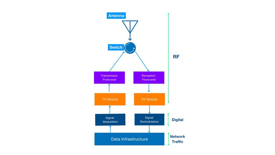
In some cases, more detailed information is required, including key performance metrics, FOMs, and even part numbers to convey the exact component, device, module, or subsystem being used in each block. In most cases, the RF interconnect used to connect the various blocks isn't displayed unless it serves a critical role at the abstraction level of the RF signal chain diagram. In some cases, the signal chain omits the antenna, antenna interface circuitry, or other peripheral circuits, as these are sometimes outside of the domain of responsibility of the design team.
An RF signal chain establishes the key performance metrics for each block, ensuring that input and output requirements are clearly defined for both transmitters and receivers. For instance, a transmitter front-end block typically has output metrics such as power, efficiency, linearity, bandwidth, and spectral content, while input metrics can include minimum power, noise, and distortion limits. Similarly, a receiver front-end block has output metrics such as minimum power and peak allowable noise, as well as a maximum power requirement at the input.
A more detailed RF signal chain will break down the individual requirements for each block and even detail the desired performance metrics for the given component, device, or module. For example, each node in each transmitter signal chain may have specific targets for power level or gain, noise limits, harmonic maximums, and phase variation ranges. Other, non-RF constraints and requirements may also be integrated into an RF signal chain, such as how much DC power can be used or how digital and analog control signals may be injected. Other aspects that may be included in an RF chain are shielding parameters, dynamic range, mechanical tolerances (e.g., vibration and shock), and environmental ruggedness FOM.
The constraints and requirements integrated into an RF signal chain help RF designers design around the given inputs and ensure they meet the output requirements. In some cases, this could be as easy as finding the right commercial-off-the-shelf component or as laborious as designing and manufacturing a device from the ground up.
Key RF Building Blocks
There are many different types of RF components and devices, and even more extensive variations of each type. These components are typically grouped into broad categories based on their primary function in the RF signal chain, including the following:
Frequency translation
Frequency and phase adjustments
Amplitude adjustments
Frequency selection
Switching
Signal directivity isolation
Multiplexing (time, frequency, phase, directivity)
Signal splitting/combining
Generation and synthesis
Signal detection, demodulation, or conversion to baseband (analog or digital)
Some RF components and devices may serve multiple functions, especially if the components are integrated into a module and the RF signal chain is at a high level of abstraction. In some cases, the RF signal chain building blocks correspond to RF circuit elements, but they may also be more complex circuits that include several RF circuits. For instance, an RF filter could be as simple as a 2D structure on a planar circuit board or a multi-element circuit with several active components as a dedicated filter module.
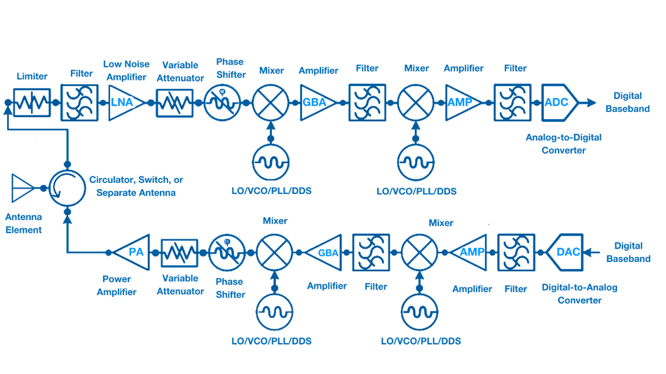
Figure 2 depicts a generic, hybrid digital/analog phased array transceiver circuit, like a hybrid analog/digital radar circuit. It presents a middle level of abstraction, displaying the key RF building blocks without showing significant details, ancillary components, or interconnects. The diagram also shows two frequency-translation stages, including two intermediate frequency (IF) stages. This is generally done when the distance between the baseband frequency and radio frequency is great enough that a single frequency translation stage would result in unacceptable signal quality at the output, such as from spurious content or harmonics.
Most common RF building blocks include:
Filters
RF filters are essentially frequency-selective attenuators. The frequency content of signals that pass through RF filters experiences minimal attenuation in the passbands (i.e., insertion loss) and significant attenuation in the stop bands. The design and complexity of an RF filter can result in multiple passbands and several stop bands. Depending on the application, these complex filters are often realized as filter banks and may also be used as diplexers or multiplexers.
The basic RF filter types are low-pass, high-pass, bandpass, and notch (or band reject).[1] The quality of the filter components and design dictate the filter response, which is generally prioritized to focus on the insertion loss, selectivity, and attenuation performance. Examples of RF filters include bulk acoustic wave (BAW), surface acoustic wave (SAW), and filter modules designed for Wi-Fi and other common wireless communication standards.
Suggested reading: BAW filters for Performance Improvements in Wi-Fi, 5G, and RF Applications
Mixers, Frequency Multipliers, Frequency Dividers, and Prescalers
RF mixers, frequency multipliers and dividers, and prescalers are all frequency translation elements. These elements translate RF signals from one frequency to another, either higher or lower, while introducing minimal distortion and nonlinearities. Mixer circuits can be passive or active, where the passive types present an insertion loss, and the active types may minimize the insertion loss or even provide gain at the output for translated signals. It is common to use an amplifier prior to a passive frequency translation component to ensure that the signals are at an adequate power level at the output of the frequency translation component and to ensure a desired dynamic range figure.
As these circuits are intrinsically nonlinear, some spurious content and harmonics are always produced. When selecting or designing mixers, engineers must account for the undesirable frequency content by-products and either filter out these by-products or ensure they exist outside of relevant frequency bands. As these devices can introduce interference and noise content into relevant frequency bands, the input and output of these devices are often filtered and even attenuated to prevent standing waves from developing at the input and output nodes of these circuits.
LOs, VCOs, PLLs, and DDS Devices
Local oscillators (LOs), voltage-controlled oscillators (VCOs), phase-locked loops (PLLs), and direct digital synthesis (DDS) devices are all used to generate desired RF signals for use as carrier frequencies or LO frequencies for frequency translation circuits. LOs are typically designed for a fixed frequency, with additional circuitry to ensure frequency accuracy and minimal phase variations. VCOs are often used as LOs in situations where it is desirable to adjust the LO frequency, either to different frequency channels or for frequency sweeping. PLLs can be used as LOs to ensure highly accurate frequency generation and can often be adjusted over a narrow range. DDS uses digital electronics and signal processing to generate digital signals that are converted to LO or RF signals using high-frequency digital-to-analog converters (DACs).
Amplifiers
RF amplifiers increase the desired signal energy while minimizing the added noise, distortion, and nonlinearities of signals passing through the amplifier circuit. There are many different types of RF amplifiers, which are generally designated based on the functions they are optimized for. For instance, power amplifiers (PAs) are designed to prioritize high power output over other performance aspects. Similarly, low-noise amplifiers (LNAs) prioritize minimal added noise while increasing the gain of low-power signals. For these reasons, PAs are most often seen at the output of transmitters, while LNAs are most often used at the input of receivers or within the RF signal chain where the gain is needed for low-power signals but minimal added noise is desired.
Other common RF amplifier types, such as gain-block amplifiers, are generally used within an RF signal chain to amplify RF signals so the signal power level is adequate after being attenuated by interconnect or other signal chain components. A broadband amplifier is designed specifically to provide a moderate amount of gain over a very wide bandwidth and can be used like a gain block amplifier.
RF Limiters, Receiver Protectors, and Digital Step Attenuators
RF limiters are devices that either shunt excessive RF energy at the input to a load or reflect the signal back toward the original path. RF limiters mainly protect sensitive components from signal energy beyond what they can handle or beyond a desired limit. They are commonly placed in the receiver signal path prior to an LNA. This prevents the LNA from being exposed to high RF power signals that could damage it or desensitize the receiver circuitry if amplified. Limiters may also be used within a signal chain if there is a chance that a failed high-power component could damage sensitive monitoring circuits or cause reflections that could damage components and devices on the same path.
In some cases, filters, usually bandpass filters, are also placed after an LNA in the receiver chain to protect and prevent the amplification of out-of-band signals. Another method of protecting sensitive receiver electronics is using a variable attenuator, such as a digital step attenuator (DSA), before the LNA in a receiver chain. The DSA can use signal-power-monitoring circuitry to determine the level of attenuation needed to ensure the signal energy in the receive path does not exceed the desired threshold. The challenge associated with using receiver protection circuitry is that any component or device before the LNA or receiver circuitry will inevitably result in insertion loss and added noise, increasing the noise floor of the receiver chain. This ultimately results in reduced dynamic range on the low end but may enhance the dynamic range on the high end in the case of filters and variable attenuators.
Multiplexers, Circulators, Switches, and Antenna Diversity
Many RF systems, including sensing, radio navigation, communication, and imaging applications, rely on both a transmission and reception signal chain, such as radar and transceivers, for communication. With purely passive systems, only a receiver is needed to pick up ambient and reflected signals generated by other sources.
However, other systems require a method that prevents the higher-power transmission signal energy from being coupled into the receiver signal chain. If the transmitter signal energy is low enough, the receiver may just be desensitized during transmission, but a high enough transmitter signal energy and coupling could damage a receiver chain. This is a problem if the transmitter and receiver share the same antenna or if the transmitter and receiver antennas need to be in proximity or are omnidirectional.
To minimize coupling in directional antennas, they should be placed at least 10 wavelengths away from each other. This can still be done with omnidirectional antennas to limit near-field coupling and allow only far-field coupling to the receive antennas, but it will still result in a significant amount of the transmitter signal energy entering the receiver. For some applications, it is desirable to have antenna diversity (different transmitter and receiver antennas), but that comes with the previously mentioned considerations.
If there is a need for greater transmitter/receiver isolation than what antenna diversity can provide, then engineers can choose from several different methods and hardware components. If it is possible to incorporate time-division multiplexing (TDM), then a synchronized switching scheme can be used where only the transmitter or receiver is switched on to the antenna path. This can provide an extremely high amount of isolation, which is why many high-power radar systems are based on TDM. If the system can achieve different frequencies for transmission and reception, then a frequency-division multiplexing (FDM) method can be used. Some cellular communication systems implement this method, using different transmit and receive frequencies and filter banks that limit adjacent channel leakage.
If it is necessary to have both transmitter and receiver activity at the same time and frequency along the same antenna transmission path, then designers can use components such as circulators. A circulator is a three-port device that shifts the signal entering a port to the next port while providing isolation among the ports. In this method, a designer connects a circulator directly to the transit, receive, and antenna paths, where the transmit signal energy will be carried to the antenna path, and the antenna-coupled signal energy will be directed to the receive path.
Digital Converters and Synthesizers
Many modern RF systems are either fully digital or hybrid analog/digital systems. This means that digital synthesizers generate RF signals, sometimes completely modulated and pre-distorted, and digital converters convert RF signals into digital signals to be processed and even demodulated. Depending on the frequencies and the performance capabilities of the digital electronics involved, designers may need to add only an RF front end (RFFE) between the digital synthesizers and digital converters to create a communication and sensing system.
Antennas
RF antennas are transducers that convert RF electrical signals to EM radiation and vice versa. They can be made from simple conductive structures, waveguides, or more complicated multi-element arrays that require sophisticated antenna processors to properly control the arrays and process the multitude of incoming and outgoing signals.
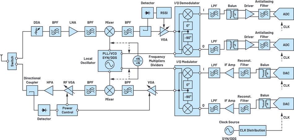
Make Versus Buy Considerations for RF Modules
Though an RF system may contain many components and devices in each signal chain, RF part manufacturers have become extremely proficient at developing complex integrated circuits (ICs) and high-density printed circuit board (PCB) modules that address many challenges of designing an RF signal chain (Fig. 3). In the simplest form, an RF module may be a relatively simple filter bank for a multiple-frequency channel wireless communication protocol or as complex as a complete RFFE, antenna processor, digitization blocks, and signal processing in one module.
The complexity and capabilities of a module generally scale the price and development curve. Moreover, there may be less flexibility when using a pre-built module. Designing a circuit or module in-house can result in a more desirable performance outcome that meets specific product requirements. However, developing RF circuits and modules requires substantial expertise and extensive equipment, testing, and technician support unless a capable contract manufacturer is commissioned. RF circuit and module development may often require more time and dedicated resources than purchasing a module. As some RF modules are pre-certified and tested for electromagnetic compatibility (EMC) compliance and other regulatory requirements, purchasing a pre-built module could dramatically shorten the development and certification time of a product.
For example, u-blox SARA-R4 series LTE-M/NB-IoT/EGPRS modules can perform simultaneous LTE communications and GNSS positioning. In order to develop such a capability internally, a design team would need to be knowledgeable of LTE, narrowband Internet of Things (NB-IoT), and GNSS technologies and have the equipment and methodologies at hand to test each of these technologies during development. Because the u-blox SARA-R4 series modules are already designed to be cost-effective, efficient, and provide end-to-end IoT communication with MQTT Anywhere and MQTT Flex, it would require many RF design team hours and upfront investment in production resources to achieve the same result in such a compact form factor, while assuming the risk of developing these capabilities.
Pre-Certified WiFi Modules by Microchip and Mouser Electronics for Wireless Design
Wi-Fi modules are self-contained hardware blocks that integrate the radio transceiver, RF front end, and security features needed to enable wireless connectivity. Because they are pre-certified, they reduce the burden of RF design, compliance testing, and regulatory approval, allowing engineers to focus on system functionality rather than low-level wireless implementation.
Microchip WILCS02 Wi-Fi® Link Controller Module
Microchip WILCS02 Wi-Fi® Link Controller Module is intended for designs where engineers need to add reliable Wi-Fi capability to a system with a host microcontroller. Acting as a dedicated network controller, it manages the RF front end, including the power amplifier, low-noise amplifier, and switching, and exposes a straightforward SDIO or SPI interface to the host.

This modular approach is useful for embedded systems that must retain a specific MCU platform due to existing codebases, toolchains, or application constraints. By offloading Wi-Fi complexity into a pre-certified package, the WILCS02 lets developers expand connectivity while avoiding RF layout challenges and compliance hurdles.
Table 1: Key features of Microchip WILCS02 Wi-Fi® Link Controller Module
Specification | Details |
Host Interface | SDIO, SPI |
Flash | Up to 2 MB (on-module) |
Radio | 2.4 GHz IEEE 802.11 b/g/n |
RF Front End | Integrated PA, LNA, TX/RX switch |
Security | Hardware crypto engines (AES, ECC, RSA, SHA), secure boot |
Antenna Options | PCB antenna (WILCS02PE) / U.FL connector (WILCS02UE) |
Certification | FCC, CE, ISED, UKCA, Wi-Fi Alliance™ |
Temp Range | -40 °C to +85 °C |
Microchip WFI32E04UE Wi-Fi® MCU Module
Microchip WFI32E04UE Wi-Fi® MCU Module goes a step further by combining a 200 MHz MIPS32 microcontroller with a 2.4 GHz 802.11 b/g/n radio in one pre-certified module. Instead of pairing Wi-Fi with an external MCU, it delivers an integrated compute-and-connect platform that can run both application code and wireless networking on the same device.

This makes it especially suitable for IoT endpoints, industrial automation, and smart appliances where reducing component count, simplifying layout, and securing communications are top priorities. With built-in support for WPA3, TLS/SSL, and multiple Wi-Fi operating modes, the module provides a ready-made foundation for secure, connected designs.
Table 2: Key features of Microchip WFI32E04UE Wi-Fi® MCU Module
Feature | Details |
MCU | 200 MHz MIPS32 M-Class microprocessor core |
Memory | 2 MB Flash, 512 kB SRAM, 128 kB buffer |
Interfaces & I/O | 3 × UART, 2 × I²C, 2 × SPI, SQI, 60 × GPIOs, USB, CAN, Ethernet |
Radio | 2.4 GHz IEEE 802.11 b/g/n |
Security | WPA3, TLS/SSL, optional hardware crypto accelerator |
Antenna | U.FL connector |
Certification | CE, FCC, ISED, MIC, KC, SRRC, NCC, UKCA |
Temp Range | -40 °C to +85 °C |
Conclusion
RF circuits and electronics are essential for many of the advanced technologies we use every day, including wireless communications in our phones and radar in our weather reports. Due to the complexity of RF systems, RF designers use the RF signal chain as an abstraction layer to simplify system-level planning and performance evaluation. This article described the value of an RF signal chain, some nuances of how RF signal chains are used, and some considerations around the risks and value of making versus buying RF modules.
References
[1] STMicroelectronics. Filters [Internet]; Available from: https://www.st.com/en/wireless-connectivity/filters.html
[2] Patyuchenko A. RF signal chain discourse - Part 2: Essential building blocks. Analog Dialogue [Internet]. 2021 Jul;55(3). Available from: https://www.analog.com/en/resources/analog-dialogue/articles/rf-signal-chain-discourse-part-2-essential-building-blocks.html

This article was originally published by Mouser Electronics. It has been edited by the Wevolver team and Ravi Y Rao for publication on Wevolver. Upcoming articles in this series will continue to explore key areas of RF engineering, offering engineers practical insights into the design and implementation of modern RF systems.