How to Specify an RF Antenna: RF Antenna Operation, Design, Selection, Testing, & Verification
Article #3 of Mastering RF Engineering: Antenna design impacts RF system performance. This article covers selection, design, testing, and compliance for RF, microwave, and mmWave applications, ensuring efficiency, reliability, and regulatory approval.

12 Dec, 2025. 15 minutes read
This is the third article in our multi-part series on “Mastering RF Engineering,” brought to you by Mouser Electronics. The series explores how RF technology is designed, built, and tested, highlighting the principles, components, and applications that make modern wireless systems possible. Each installment introduces a new dimension of RF engineering, giving readers a structured path from fundamentals to advanced practice.

Articles from this series:
- An Introduction to RF Theory, Practices, and Components
- Understanding RF Signal Chains: Key Building Blocks and Components
- How to Specify an RF Antenna: RF Antenna Operation, Design, Selection, Testing, & Verification
- Understanding RF Circuit Fabrication and Interconnects
- Digital RF Technology Explained: How Digital Signal Processing is Revolutionizing Wireless Systems
- Understanding RF Applications: Communication, Sensing, Power Transfer and Beyond
- The Fundamentals of RF Testing and Measurement Techniques
All radiofrequency (RF), microwave, millimeter-wave (mmWave), and terahertz-wave technologies that send or receive signals need one key component that can make or break the entire system: the RF antenna.
Unoptimized antenna design or selection can render an entire RF system completely non-functional and even dangerous, regardless of the quality of the design and fabrication of the system. RF antenna design and selection are sometimes considered separately from RF system design. This often leaves design teams either struggling at the end of a design cycle to develop an antenna that can achieve system performance goals or contracting other manufacturers to take on the burden of antenna design.
In some instances, a system may be designed to accept generic antennas while sacrificing some performance for versatility with antenna selection. Whatever the case, selecting or designing an appropriate RF antenna for an RF system is as pivotal to overall system performance as selecting other major components, such as amplifiers, mixers, filters, and frequency synthesizers and generators.
When specifying an optimized antenna for a given application, designers must carefully consider the system's performance criteria, materials, and environmental constraints. Additionally, most regions, governments, and industries require rigorous certification and compliance testing of new RF systems, which often hinge on antenna performance.
This article surveys RF antennas, including how they work, key performance criteria, and common types. It also explores antenna design, selection, testing, and verification in new RF systems.
Understanding RF Antennas
An antenna is a fundamental transducer that converts electrical signals carried through conductors, transmission lines, or waveguides into electromagnetic waves that travel through space. RF antennas operate reciprocally, meaning they convert electrical signals into electromagnetic waves and vice versa, with the same efficiency in both directions.
Transmission occurs when a transmitter directs an electrical signal to the antenna terminals, causing magnetic and electric fields to develop along the antenna structure. These fields eventually transform into electromagnetic waves traveling away from the antenna in a pattern dictated by the antenna geometry. Reception occurs when electromagnetic waves in space collide with an antenna structure. The waves then induce electrical signals carried along a conductor or transmission line or are captured by an aperture and converted to guided waves within a waveguide.
Antenna Feeds and Signal Transmission
Antennas are often driven via feed lines or feeds, which are typically transmission lines or waveguides designed to efficiently direct the electrical signals to and from the RF system to the antenna terminals.
Nearby dielectric or conductive objects can affect the electric, magnetic, and electromagnetic fields around an antenna. These interactions impact performance, as field size, shape, and behavior depend on the antenna's structure and the frequency of the signal.
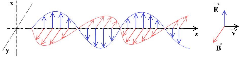
The distance at which electric, magnetic, or electromagnetic coupling can occur depends on the wavelength of the electrical signals, with lower-frequency signals coupling more efficiently at greater distances. In antenna structures, three different field regions exist depending on frequency: near field, radiative near field, and far field. The near field includes the reactive or inductive region, where electric and magnetic field coupling occurs. The radiative near field (known as the Fresnel region) is where electromagnetic fields are not strictly perpendicular and have not yet formed a plane wave. In the far field, electromagnetic waves establish a true plane wave with perpendicular electric and magnetic field vectors. The electric and magnetic fields of a uniform plane wave are truly perpendicular, with a clear direction of propagation orthogonal to the electric and magnetic field directions. The direction of propagation of a uniform plane wave is known as the Poynting vector.
Objects within the near-field range can affect antennas via loading or other complex coupling dynamics. Antenna loading occurs when an inductive or capacitive element induces a change of behavior in an antenna, by design or otherwise. This phenomenon is used in antenna design to influence the antenna pattern, gain, directivity, efficiency, bandwidth, and other specifications.
Far-Field vs. Near-Field Considerations
Most antennas are specified for their far-field performance, though specialized probes and certain types of near-field antennas are often used to test antenna systems. There are no clear boundaries between the antenna field regions, and a variety of different models are used to estimate or predict the transitions between these regions. However, beyond the far-field boundary, electromagnetic energy can be considered a pure radiating plane wave, significantly reducing the complexity of mathematically analyzing an antenna.
Antenna Performance Criteria
The following are key performance criteria used to specify RF antennas:
Polarization
Radiation/antenna pattern
Directivity
Gain
Beamwidth
Effective area/aperture
Efficiency
Impedance
Voltage standing wave ratio (VSWR)
Return loss
Resonance
Bandwidth
Power handling
Environmental ruggedness
Feed interconnect
Polarization and Its Impact on Performance
Polarization describes the orientation of the electric field portion of the antenna plane wave with respect to the surface of the earth. An antenna can be either linearly or circularly polarized. Linear polarization is either vertical or horizontal, and circular polarization is either left-hand or right-hand. More accurately, all polarizations are elliptical, with linear polarization collapsing the electric field oscillating pattern of the ellipse into a line and circular polarization presenting a perfect rotation around the direction of propagation. There is a substantial reduction in antenna coupling efficiency when the antenna polarization and electromagnetic wave polarization are misaligned.
Radiation Pattern, Directivity, Gain, and Beamwidth
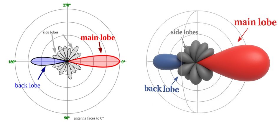
An antenna's radiation pattern (also known as antenna pattern) is the three-dimensional distribution of the electromagnetic radiation from the antenna. By design, most antennas have primarily lobe patterns, with undesirable sidelobes reducing the antenna’s directivity and gain. An antenna’s directivity is a measure of how concentrated the antenna radiation pattern is compared to a perfectly isotropic spherical antenna pattern.
This concept directly relates to antenna gain, as the gain of an antenna is the ratio of energy of an actual antenna’s radiation pattern compared to that of a perfectly spherical (ideal) isotropic antenna. The following equation expresses antenna gain (G), where D is the directivity of the antenna, and ε is the radiation efficiency, which accounts for losses due to resistance, mismatches, and material imperfections:
G = εD
Antennas don’t provide additional energy to a signal, as amplifier gain does, which is why antenna gain is a comparative measure that relates to directivity; the antenna radiation must be concentrated to realize gain in relation to an antenna with a conformal energy output in a spherical pattern.
An antenna’s beamwidth is the angular width measurement across the axis of the main lobe of a directional antenna, typically given in degrees or radians.
Effective Area and Antenna Efficiency
An antenna’s effective area (or effective aperture) is a measure of the captured power flux density of a passing electromagnetic wave by an antenna. In other words, it is a ratio of the total available power of a wave (incident co-polarized power density) that an antenna can capture and deliver to a conjugate matched load. This measurement is given as a function of the direction to the source of the captured radiation for directional antennas with matched polarization.
Antenna efficiency is how much of the energy captured from an electromagnetic wave is delivered to the antenna terminals or how much of the energy directed to the antenna terminals is converted to radiated energy. As all practical antennas have losses, antenna efficiency is always less than 100 percent, and efficiency impacts the antenna’s effective area, gain, and directivity.
Impedance Matching, VSWR, and Return Loss
The impedance match of an antenna's terminals to the feed line affects the VSWR and return loss metrics. If the impedance match is perfect, the antenna carries 100 percent of the signal energy. However, practical systems cannot provide perfectly matched impedance, and some energy will reflect from the antenna terminals and form a standing wave. The standing wave is characterized by the standing wave ratio (SWR) or, if measured in voltage, VSWR.
Antenna tuning circuits are often used to enhance the impedance match between the antenna and feed line over a desired frequency range. Reactance, which arises when inductors and capacitors oppose alternating current by storing and releasing energy in magnetic and electric fields, can affect this match. To compensate for this, tuning circuits use physical conductor or dielectric structures or a reactance network that cancels the reactance of the antenna at the feed point.
Transformers at the antenna and feed node, such as a balun, may be used to match balanced/unbalanced antenna and feed lines to prevent substantial reflections.
Resonance and Bandwidth Optimization
The physical structure of an antenna and tuning network (known as a transmatch) may be designed to allow for resonance to occur, or resonances may be the by-product of design and structure. Resonance is when an antenna's reactance is zero, presenting a purely resistive feed point impedance.
Depending on the quality of the resonance (Q), the electrical length or effective area can be substantially more than the non-resonant electrical length or effective area. This makes a resonant antenna attractive for narrow-band applications because the resonance operates over a limited bandwidth. Other methods exist, such as combining different resonant structures, using fractal designs, or tuning to enhance the bandwidth of an antenna over a greater frequency range.
Power Handling and Thermal Considerations
The power handling capability of an antenna is a measure of the maximum (peak) and continuous power an antenna can radiate before derating or being damaged. As all conductive elements of an antenna have losses, some of the transmitted and received energy is converted to thermal energy. Excessive transmit or receive power can result in overheated elements that damage the antenna and possibly degrade or destroy any dielectric structures or radomes.
Environmental Durability and Protection
Another set of antenna parameters is the environmental conditions for which an antenna is suitable. Factors such as temperature, wind shear, shock, vibration, radiation, cosmic weather, corrosive gases or liquids, and humidity are all common considerations for antennas in extreme environments. In response, engineers often use radomes to protect more sensitive antenna elements. However, radomes also affect the behavior and performance of an antenna system.
Feed Interconnect
The feed interconnect dictates how the feed line is connected between the transmitter/receiver and the antenna terminals. Typical antenna feeds include single conductors, dual conductors, transmission lines, and waveguides.
Antenna Types
Antennas are typically categorized as either omnidirectional or directional. Omnidirectional antennas present a 360-degree azimuth antenna pattern with varying degrees of vertical coverage. Directional antennas are concentrated on a specific direction or a limited range of directions, presenting an azimuth antenna pattern of less than 360 degrees.
Common antenna types include aperture, reflector, lens, array, and metamaterial.
Types of aperture antennas, not to be confused with the aperture of an antenna, include waveguide horns, slots, and other cavity-type antennas.
Reflector antennas, such as parabolic dish antennas, are designed using a reflective structure and a feed antenna that directs the electromagnetic waves to the reflector to achieve a desired antenna pattern. This generally enhances directivity, as the radiated energy is concentrated in a specific direction rather than spread in multiple directions. The reflector helps convert a spherical wave—where electromagnetic waves radiate outward in all directions from a point source—into a collimated plane wave, meaning the wavefronts are parallel and travel in a single direction along the reflector axis, improving signal focus and efficiency.
Lens antennas use dielectric structures to warp the path of the wavefront emitted by a feed antenna. They can be used similarly to reflector antennas to enhance directivity, or to reduce directivity and enhance the beamwidth. Depending on the complexity of a lens antenna, the dielectric structure can be designed to be frequency selective.
Array antennas use a line, grid, or mesh of smaller antenna structures that can behave as a much larger antenna that may otherwise be impractical to fabricate. With the appropriate electronics, array antennas can be made electronically steerable and facilitate spatial diversity schemes, such as multi-input multi-output (MIMO).
Metamaterial antennas are a diverse class of antennas made using dielectric or conductive structures. They use electromagnetic phenomena and geometry to achieve antenna behavior that is different from what can be achieved with bulk materials.
Antenna Design and Selection
Designing and selecting an antenna involves evaluating the performance dynamics and criteria of the rest of the RF system (e.g., transmitter or receiver dynamics), application requirements for communication or sensing technology, and the constraints of regional spectrum and safety regulations.
Matching Antennas to Existing Systems
In some cases, an antenna is selected based on available resources and technologies after an RF system has been designed. In this case, an antenna must conform to all the other criteria without the ability to modify the attached RF system. Alternatively, the design of the entire RF system could be concurrent with the antenna design or selection. In this scenario, engineers can account for antenna performance during system-level design.
In the simplest cases, such as selecting a Wi-Fi router antenna or an antenna for a prebuilt Internet of Things (IoT) module, the top concerns are matching antenna bandwidth, gain, directivity, radiation pattern, impedance, interconnect, and power handling. An antenna's cost and physical dimensions often also significantly impact the design and selection.
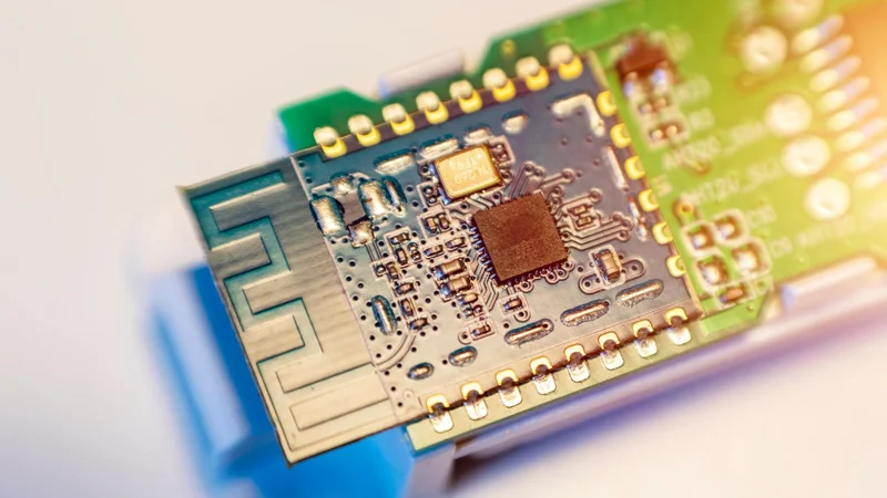
For instance, some IoT module and portable electronics designers may prefer to incorporate extremely compact or integrated antenna designs. There are methods of integrating antenna designs into the electronics housing, fabricating antennas with PCB metallization, using attachable antenna modules to the electronics feed directly on a substrate (i.e., chip antennas), and even using the housing of the electronic structure as an antenna. All these methods are commonly used for portable, mobile, or integrated antennas. Still, external antenna structures are typically used in large platforms, such as vehicles, aircraft, and ships, as the RF equipment is generally protected or housed within the platform, and interconnects are needed to route signals between the RF equipment and antenna.
Antenna Arrays and Advanced Design Considerations
Antenna arrays can be designed as relatively simple static structures with fixed attenuators or phase shifters that generate a specific antenna pattern and meet other performance specifications. Conversely, some arrays incorporate more advanced attenuation and phase adjustments to enable active beamforming and beamsteering, along with antenna processing circuits that support spatial multiplexing.
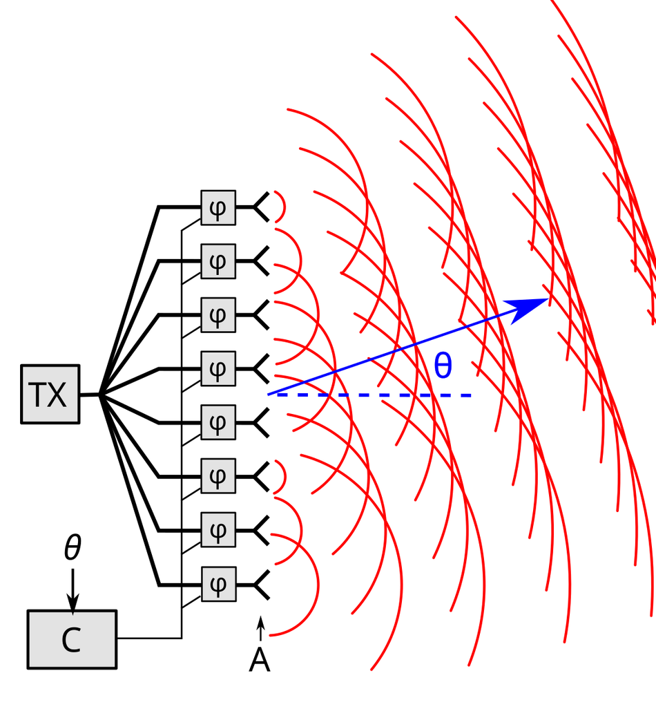
Such an antenna design is likely not viable without the complex beamforming or beamsteering and spatial multiplexing circuit, in addition to a much more complex RF front-end (RFFE) and antenna feed interconnect. These systems may use multiple transmit and receive (TRX) signal chains, sometimes with a dedicated TRX for each antenna element in the array. The performance and flexibility of such systems can be advantageous for communication and sensing (i.e., radar) applications with extreme performance requirements. However, such system complexity comes with associated high costs and fabrication hurdles that must be overcome.
Electromagnetic Simulation for Antenna Design
A substantial amount of research has been done on various antenna designs, and guidance has been given on how to approach the designs from a practical standpoint. However, the sensitivity of antenna designs to fabrication tolerances and placement nuances within a structure or environment makes even basic antenna design extremely complex. This is why there are advanced software suites with full-electromagnetic simulation solvers that use a variety of methods to solve the complex interactions of conductors, dielectrics, current, voltage, and fields. These solvers have become incredibly accurate and, with high-performance computing (HPC) and other simulation acceleration technologies, can perform parametric optimizations over wide ranges in relatively short periods of time.
However, even with such advanced tools, antenna design is still incredibly nuanced, and getting accurate and repeatable results from these tools requires a steep learning curve. Manufacturers and other companies offer design and validation services that leverage these simulation tools, helping engineers refine their antenna designs before moving to production.
Antenna Testing and Verification
Using specific software tools can dramatically increase the ease, pace, and accuracy of antenna design. However, even with the highest quality control and precision fabrication, no simulation solver can perfectly predict antenna behavior in a real-world environment. This is why extensive hardware and software tools exist for testing antennas either in isolation or as part of an RF system.
For example, basic testing antennas, such as waveguide horns, are often used to perform various tests on other antennas. There are many types of test antennas and antenna test configurations, some of which involve highly advanced and complex testing setups. These systems use multiple probes and motion mechanisms to generate detailed 3D scans of the entire antenna radiation pattern.
The level of testing needed for a given antenna often depends on its performance goals, research data goals, and available budget. Typically, more rigorous testing produces results that can be used to enhance an antenna design or even a complex RF system design. But this comes at a premium and requires an RF design team with advanced expertise for the full extent of usefulness. Some more modern test systems produce results that can be used within simulation software suites (to optimize a design further) or alongside circuit simulations of the rest of the RF system.
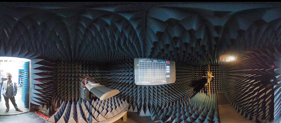
To properly test an RF antenna, the environment must be electromagnetically isolated from external interference, noise, and objects within the vicinity of the near-field regions of the antenna. This is why organizations often use open-air test ranges in remote areas with minimal outside interference. Another method is to construct a shielded chamber, sometimes with an absorptive interior structure, to isolate an antenna from the external environment. Installations like these are called anechoic chambers, test chambers, or test cells, depending on the type of structure. Some chambers specifically designed for antenna testing are simply called antenna test chambers.
Most global regions have spectrum regulations, known as electromagnetic compliance (EMC) and electromagnetic interference (EMI) testing, that limit the use of certain portions of the spectrum from interference or hazardous RF signal energy. Hence, it is vital to account for antenna gain and efficiency when designing or selecting an antenna for an application in a regulated spectrum, as the antenna performance can impact the signal's output power, frequency accuracy, and phase accuracy.
In addition to EMC and EMI, most regions have spectrum regulations based on frequency, application, and end-use environment. Additionally, most wireless protocols have specifications that must be met to attain certification, and antenna selection is often a critical aspect of meeting these. Many countries and regions around the world will not allow products to be sold or even shipped into their region without proper certification by approved testing facilities.
Featured Antenna Solutions from TE Connectivity and Mouser Electronics
As wireless applications expand across all the sectors, antenna performance and reliability remain at the core of system design. Compact form factors, multi-band coverage, and robust environmental resilience are increasingly critical as devices demand seamless connectivity. TE Connectivity addresses these needs with a broad antenna portfolio, including solutions that integrate multiple communication standards into a single design.
TE Connectivity / Linx Technologies GNSS L1 Passive Ceramic Patch & Chip Antennas
TE Connectivity / Linx Technologies GNSS L1 Passive Ceramic Patch & Chip Antennas provide high performance and reliable satellite positioning across GPS, Galileo, and BeiDou systems. Operating in the 1561MHz to 1602MHz band with a 50Ω impedance, these antennas are available in both surface-mount and through-hole configurations to suit diverse hardware requirements.

Patch antenna variants are offered in 25mm × 25mm, 20mm × 20mm, and 18mm × 18mm sizes, while the miniature 3mm × 1.6mm × 0.6mm chip antenna enables integration into highly compact designs. With applications ranging from asset tracking and smart home automation to precision surveying and industrial IoT, these antennas combine efficiency with flexibility.
Table 1: Key features of TE Connectivity / Linx Technologies GNSS L1 Passive Ceramic Patch & Chip Antennas
Feature | Details |
Frequency Range | 1561MHz to 1602MHz / 1575MHz to 1602MHz |
Impedance | 50Ω |
Mounting Options | Surface mount, Through-hole |
Dimensions | Patch: 25×25mm, 20×20mm, 18×18mm Chip: 3×1.6×0.6mm |
Applications | GPS, Galileo, BeiDou, IoT, IIoT, Smart Home, Asset Tracking, Precision Surveying, Navigation Systems, Wearables, Consumer Devices |
TE Connectivity FP40 Auto Antennas
The FP40 Auto Antennas from TE Connectivity are engineered to deliver an all-in-one solution for modern vehicular connectivity. Covering LTE/5G, Wi-Fi 6E/7, Bluetooth, and GNSS (L1 and L5), these antennas support up to eight ports and optional whip elements for VHF, UHF, and sub-GHz frequencies. Their aerodynamic design and robust ingress protection ratings make them suitable for integration into a wide range of vehicles, including emergency fleets, public transportation, and utility systems.

With 4×5G MIMO capability and an aluminum baseplate construction, FP40 Auto Antennas provide reliable high-bandwidth performance in demanding environments. This makes them an ideal choice for vehicular gateways, routers, and telematics platforms that require secure, multi-band connectivity under challenging conditions.
Table 2: Key features of TE Connectivity FP40 Auto Antennas
Feature | Details |
Supported Bands | 4G, 5G, CBRS, Wi-Fi® 6E/7, BLUETOOTH®, GNSS L1/L5, VHF/UHF, 700–900MHz |
Ports | Up to 8 |
Special Features | 4×5G MIMO, optional whip antenna, multi-port aerodynamic solution |
Dimensions | 245mm × 63mm × 84mm |
Mounting | P-mount |
Material | Aluminum baseplate |
Environmental | IP67, IP69K |
Operating Temperature | -40°C to +85°C |
Applications | Vehicular Gateways, Routers, Public Safety, Public Transportation, Utility Vehicles, Telematics, Emergency Services |
Conclusion
The nuances and complexity of RF antenna design, testing, and verification often lead organizations to outsource antenna development to dedicated RF antenna design houses instead of developing them internally.
Overcoming challenges to antenna design and selection while meeting regional regulations and certifications is often the difference between quickly bringing a competitive product to market and exceeding budgets and delaying development. To meet these needs, dedicated antenna design organizations specialize in one or more of the many antenna types and applications.

This article was originally published by Mouser Electronics. It has been edited by the Wevolver team and Ravi Y Rao for publication on Wevolver. Upcoming articles in this series will continue to explore key areas of RF engineering, offering engineers practical insights into the design and implementation of modern RF systems.