Stripline vs Microstrip: A Comprehensive Comparison
This article provides a detailed understanding of stripline vs microstrip, their structure, working principle, advantages and disadvantages, comparative analysis, and choosing the right one for your application.

06 Nov, 2023. 16 minutes read
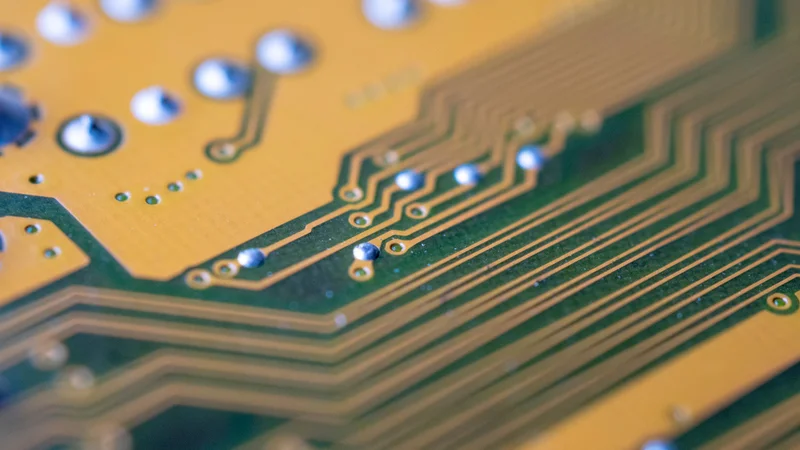
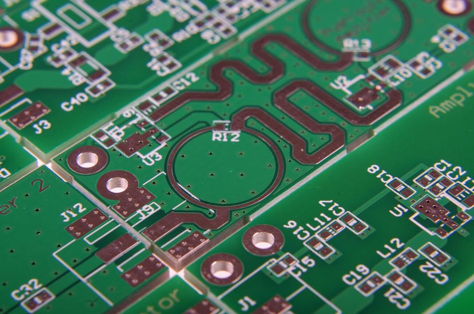
Closeup view of PCB with stripline vs microstrip
Introduction to Stripline and Microstrip
Transmission lines are essential in electronics and telecommunications, guiding electrical energy from one point to another, ensuring the transmission of signals with minimal dielectric loss. Two common transmission lines used in various applications are stripline and microstrip. What’s going to be stripline vs microstrip?
A stripline is a flat conductor sandwiched between two parallel ground planes, often made of copper, and enclosed within a dielectric material and a metal casing. The center conductor in a stripline is typically a copper strip. Striplines are used in various applications, including microwave circuits, antennas, and high-speed digital circuits.
Like striplines, microstrips are commonly made of copper and are used in similar applications. However, microstrips are not fully enclosed, allowing easier access and manipulation.
Both stripline vs microstrip have their unique advantages and disadvantages, which make them suitable for different applications. Understanding these differences is crucial for engineers and designers when choosing the appropriate transmission line for a specific application.
Understanding Stripline
A stripline, often called a planar transmission line or PCB transmission line, is a crucial component in electronics and telecommunications. It is a type of transmission line that is routed on the inner layers of a PCB design between two ground planes.
The Structure of Stripline
The physical structure of a stripline is unique and contributes significantly to its functionality. It consists of a flat conductor sandwiched between two parallel ground planes. The conductor is typically made of copper due to its excellent electrical conductivity. The copper conductor is embedded within a dielectric material, which is then enclosed by a metal casing.
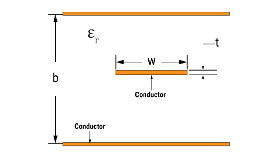
The dielectric material plays a crucial role in the operation of the stripline. It is responsible for maintaining the separation between the conductor and the ground planes, and it also determines the speed at which signals travel through the stripline. The dielectric constant of the material, denoted by 𝜺ᵣ, is a key parameter in this regard. Commonly used dielectric materials include FR-4, with a dielectric constant of approximately 4.5, and PTFE (also known as Teflon), with a dielectric constant of around 2.0. [1]
The metal casing, usually made of a conductive material like copper or aluminum, serves as the ground plane for the stripline. It provides a return path for the current and shields the conductor from external electromagnetic interference.
The dimensions of the stripline, including the thickness of the conductor and the dielectric and the trace width of the stripline, are carefully chosen based on the desired impedance and frequency characteristics. For instance, a wider stripline will have a lower characteristic impedance, while a thicker dielectric internal layer will result in slower signal propagation.
Edge-coupled stripline is a type of stripline where the two conductors are placed side-by-side on the edge of a dielectric substrate. On the other hand, a broadside-coupled stripline is a type of stripline where the two conductors are placed side-by-side on the same layer of the dielectric substrate. This type of stripline is often used for differential pairs, where the two conductors carry signals that are inverted versions of each other. Similarly, a symmetric stripline is a type of stripline where the two ground planes are equidistant from the center conductor.
In summary, the structure of a stripline is a complex assembly of carefully chosen materials and dimensions, each contributing to its overall performance and functionality. Understanding this structure is key to leveraging the advantages of striplines in various applications.
Working Principle of Stripline
The working principle of a stripline revolves around the propagation of electromagnetic waves along the conductor, which is sandwiched between two ground planes. The dielectric material surrounding the conductor plays a crucial role in this process.
When an electrical signal is applied to the stripline, it generates an electromagnetic field around the conductor. This field interacts with the dielectric material, causing the signal to propagate along the length of the stripline. The speed at which the signal travels, also known as the propagation speed, is determined by the dielectric constant of the material.
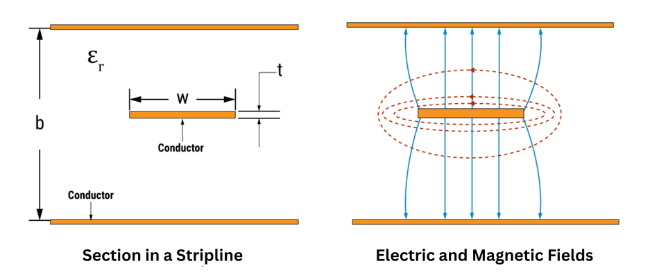
The propagation of signals in a stripline follows the TEM (Transverse Electromagnetic) mode. In this mode, both the electric and magnetic fields are perpendicular to the direction of propagation. [2] This is a desirable characteristic as it results in low signal distortion and attenuation, making striplines suitable for high-frequency applications.
The ground planes on either side of the conductor serve a dual purpose. Firstly, they provide a return path for the current, completing the electrical circuit. Secondly, they shield the conductor from external electromagnetic interference, ensuring the signal integrity is maintained.
The impedance of the stripline is a critical parameter for signal transmission. It is determined by the geometry of the stripline and the properties of the dielectric material. It is given by the formula:

where Z₀ is the characteristic Impedance, 𝜺ᵣ is the relative permittivity of the dielectric, 𝒉 is the height of the dielectric, and 𝒕 is the substrate thickness. [3] This formula shows that the impedance can be controlled by adjusting the dimensions of the stripline and the choice of dielectric material.
In conclusion, the working principle of a stripline involves the propagation of electromagnetic waves along a conductor, with the dielectric material and ground planes playing key roles in the process. Understanding this principle is essential for leveraging the advantages of striplines in various applications.
Advantages of Stripline
Striplines offer several advantages that make them a preferred choice for certain applications, particularly those involving high frequencies.
One of the primary advantages of striplines is their ability to support pure transverse electromagnetic mode (TEM) propagation. The TEM mode also ensures that the signal velocity is independent of frequency, leading to minimal dispersion.
Striplines also offer excellent isolation between adjacent traces due to the presence of ground planes on both sides of the conductor. This feature reduces cross-talk, which is a common issue in high-density circuits where multiple transmission lines are closely packed together.
Another advantage of striplines is their immunity to external electromagnetic interference. This is because the waveguide in a stripline prevents the electromagnetic field from propagating outside of the stripline. Differential pairs can help to reduce EMI by canceling out common-mode noise. Therefore, striplines with differential pairs are the best choice for applications where EMI must be minimized.
Striplines also have a consistent characteristic impedance, which is determined by the geometry of the stripline and the properties of the dielectric material. This consistent impedance reduces signal reflections, thereby improving signal integrity.
Finally, striplines allow for the integration of active and passive components within the same layer, leading to more compact and efficient circuit designs. There are a variety of different types of connectors available for striplines. This is particularly beneficial in applications where space and weight are critical considerations, such as aerospace and defense systems.
Stripline has a higher capacitance than microstrip, which can be advantageous in some applications. For example, striplines can be used to create filters that can block certain frequencies.
In conclusion, the advantages of striplines, including their support for TEM mode propagation, excellent isolation, immunity to electromagnetic interference, consistent impedance, and compact design, make them versatile solutions for a wide range of applications.
Disadvantages of Stripline
Despite the numerous advantages, striplines also have certain limitations that can affect their performance and suitability for some applications.
One of the main disadvantages of striplines is their complex and bulky structure. The need for two ground planes and a dielectric material sandwiching the conductor makes the stripline thicker than other types of transmission lines like microstrip. This can be a disadvantage in applications where space is a critical factor.
The fabrication of striplines is also more complex and costly compared to other transmission lines. The process requires precise control over the dimensions and properties of the materials used, which can increase the manufacturing cost. This can be a significant factor in large-scale production where cost-effectiveness is a priority.
Another limitation of striplines is the difficulty in accessing the conductor for testing and troubleshooting. Since the conductor is sandwiched between two ground planes, it is not directly accessible. This can make it challenging to perform in-circuit testing or modify the circuit once fabricated.
Heat dissipation can also be a concern in striplines. The enclosed structure of the stripline can trap heat generated by the signal transmission, which can lead to thermal issues. This can affect the performance and reliability of the stripline, especially in high-power applications.
Finally, striplines can lead to a slower signal propagation speed than other transmission lines. This is because the signal velocity in a stripline is determined by the dielectric constant of the material, which is typically lower than the speed of light in a vacuum.
In conclusion, while striplines offer several advantages regarding signal integrity and isolation, they also have disadvantages related to their physical structure, fabrication complexity, accessibility, heat dissipation, and signal propagation speed. These factors must be carefully considered when choosing a stripline for a specific application.
Recommended Reading: Trace PCB: A Comprehensive Guide
Understanding Microstrip
Microstrip is another type of transmission line that is widely used in the field of electronics and telecommunications. Like a stripline, it guides electrical energy from one point to another, ensuring efficient and minimal loss signal transmission. However, the structure and characteristics of microstrip are different from those of striplines, which leads to different advantages and disadvantages.
The Structure of Microstrip
The structure of a microstrip is simpler than that of a stripline. It consists of a conducting strip separated from a ground plane by a dielectric layer. The conducting strip, typically made of copper due to its excellent electrical conductivity, serves as the signal line.
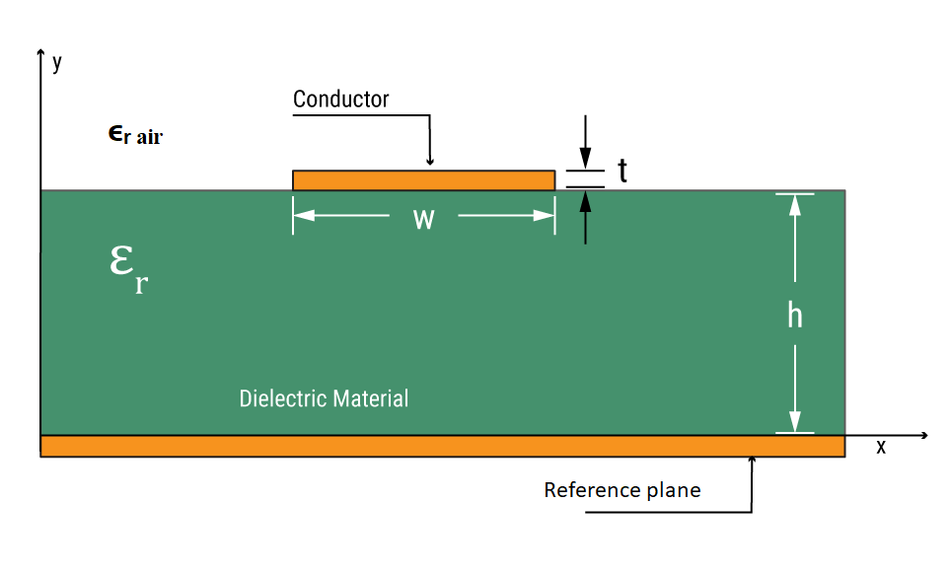
The dielectric multilayer plays a crucial role in the operation of the microstrip. It maintains the separation between the conductor and the ground plane and determines the speed at which signals travel through the microstrip. The dielectric constant of the material, denoted by 𝜺ᵣ, is a key parameter in this regard. Commonly used dielectric materials include FR-4, with a dielectric constant of approximately 4.5, and PTFE (also known as Teflon), with a dielectric constant of around 2.0.
The ground plane, usually made of a conductive material like copper or aluminum, provides a return path for the current and shields the conductor from external electromagnetic interference. However, unlike in a stripline, the ground plane in a microstrip is only on one side of the conductor.
The dimensions of the microstrip, including the thickness of the conductor and the dielectric, and the width of the microstrip, are carefully chosen based on the desired impedance and frequency characteristics. For instance, a wider microstrip will have a lower characteristic impedance, while a thicker dielectric layer will result in slower signal propagation.
Coplanar waveguide (CPW) is a type of transmission line where the center conductor is placed on the surface of a dielectric substrate, and the ground planes are placed on either side of the center conductor. CPW is similar to microstrip, but it has a lower capacitance and is less susceptible to radiation losses.
In summary, the structure of an embedded microstrip is a simpler assembly of carefully chosen materials and dimensions, each contributing to its overall performance and functionality. Understanding this structure is key to leveraging the advantages of microstrip in various applications.
Working Principle of Microstrip
The working principle of a microstrip is based on the propagation of electromagnetic waves along the conducting strip, which is separated from the ground plane by a dielectric layer. The dielectric material plays a vital role in this process, affecting the speed at which signals travel through the microstrip.
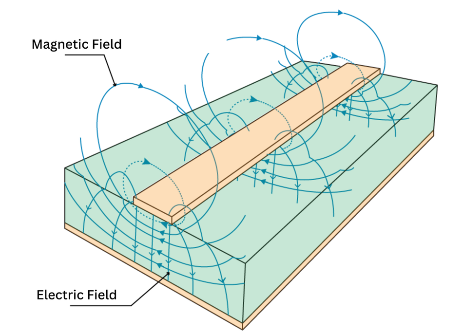
When an electrical signal is applied to the microstrip, it generates an electromagnetic field around the conductor. This field interacts with the dielectric material, causing the signal to propagate along the length of the microstrip. The speed at which the signal travels, also known as the propagation speed, is determined by the dielectric constant of the material.
Unlike striplines, which support pure transverse electromagnetic (TEM) mode propagation, microstrips typically exhibit quasi-TEM mode propagation. [4] In this mode, the electric and magnetic fields are not strictly perpendicular to the direction of propagation, and the signal velocity is slightly frequency-dependent. This can result in some dispersion and signal distortion, particularly at higher frequencies.
The ground plane in a microstrip serves two primary purposes. First, it provides a return path for the current, completing the electrical circuit. Second, it shields the conductor from external electromagnetic interference (EMI), ensuring that the signal integrity is maintained.
The impedance of the microstrip, a critical parameter for signal transmission, is determined by the geometry of the microstrip and the properties of the dielectric material. It is given by the formula:

where Z₀ is the characteristic Impedance, 𝜺ᵣ is the relative permittivity of the dielectric, 𝒉 is the height of the dielectric, and 𝒕 is the thickness of the conductor. [5] This formula shows that the impedance can be controlled by adjusting the dimensions of the microstrip and the choice of dielectric material.
In conclusion, the working principle of a microstrip involves the propagation of electromagnetic waves along a conductor, with the dielectric material and ground plane playing key roles in the process. Understanding this principle is essential for leveraging the advantages of microstrips in various applications.
Advantages of Microstrip
Microstrip transmission lines offer several advantages that make them a popular choice for many applications, particularly in high-frequency electronics.
One of the primary advantages of microstrips is their simple structure. Consisting of a single conducting strip separated from a ground plane by a dielectric layer, microstrips are easier and less expensive to fabricate than striplines. This simplicity also allows for easier access to the conductor for testing and modifications, which can be a significant advantage during the design and troubleshooting stages.
Microstrips can support lumped and distributed elements. This allows for integrating various components, such as resistors, capacitors, and inductors, directly onto the microstrip line, leading to more compact and efficient circuit designs.
Another advantage of microstrips is their ability to radiate a small amount of power. While this can be a disadvantage in certain applications due to potential interference, it can benefit others. For instance, in antenna design, the radiating characteristic of microstrips can be leveraged to create compact and efficient microstrip antennas.
Microstrips also have a higher power handling capacity compared to striplines. This is due to their open structure, which allows for better heat dissipation. This makes microstrips suitable for applications where high power levels are involved.
Finally, the signal propagation speed in a microstrip is higher than in a stripline. This is because the effective dielectric constant in a microstrip is less than in a stripline due to the fact that the electromagnetic field in a microstrip is not fully confined within the dielectric material.
In conclusion, the advantages of microstrips, including their simplicity, versatility, radiating characteristics, high power handling capacity, and faster signal propagation speed, make them an effective solution for various applications.
Disadvantages of Microstrip
While microstrip transmission lines offer several advantages, they also have certain limitations that can affect their performance and suitability for some applications.
One of the main disadvantages of microstrips is their susceptibility to external electromagnetic interference. Unlike striplines, which have ground planes on both sides of the conductor, microstrips have a ground plane only on one side. This open structure makes them more vulnerable to interference from nearby components or external sources, which can degrade signal integrity.
Another limitation of microstrips is their quasi-TEM mode of propagation. This mode results in a slightly frequency-dependent signal velocity, which can lead to dispersion and signal distortion, particularly at higher frequencies. In contrast, striplines support pure TEM mode propagation, which exhibits minimal dispersion and distortion.
Microstrips also exhibit higher levels of cross-talk compared to striplines. The open structure of microstrips allows for electromagnetic coupling between adjacent transmission lines, which can lead to unwanted signal interference. This can be a significant issue in high-density circuits where multiple transmission lines are closely packed.
The radiating characteristic of microstrips, while advantageous in some applications, can also be a disadvantage in others. The radiation of power from the microstrip can lead to potential interference with nearby components or circuits, which may require additional shielding or isolation measures to maintain signal integrity.
Finally, microstrips have a lower characteristic impedance range compared to striplines. This can limit their suitability for certain applications where a specific impedance value is required. Designers must carefully consider the impedance requirements of their application when choosing between microstrip and stripline transmission lines.
In conclusion, the disadvantages of microstrips, including their susceptibility to electromagnetic interference, quasi-TEM mode propagation, higher cross-talk, radiating characteristics, and limited impedance range, must be carefully considered when selecting a microstrip for a specific application.
Recommended Reading: PCB Material: A Comprehensive Guide to Understanding and Choosing the Right Materials
Stripline vs Microstrip: A Comparative Analysis
Stripline and microstrip are two types of low-impedance and planar transmission lines that are commonly used for high-frequency signal transmission in printed circuit boards (PCBs). They have similarities and differences in structure, working principles, advantages, and disadvantages. Comparing them can help choose the right type for an application. [6]
Comparison Based on Structure
The line structure of a stripline and microstrip are fundamentally different, which directly impacts their performance and application.
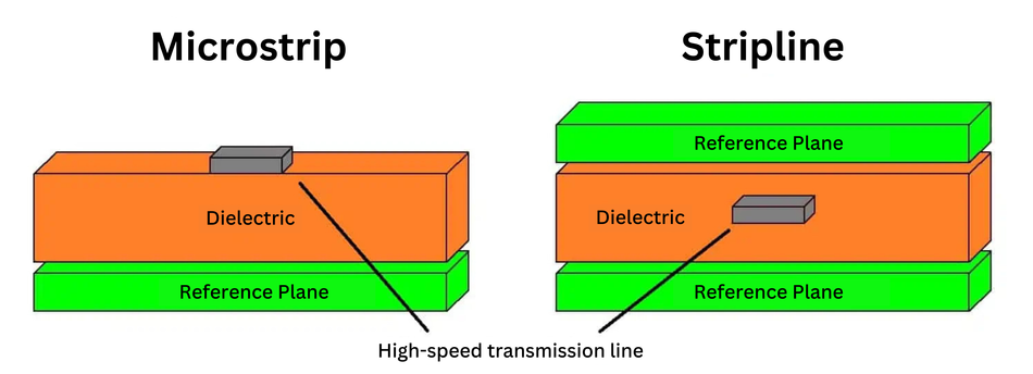
The dielectric substrate in a stripline or microstrip PCB is an insulator. A stripline is a type of transmission line that consists of a conductor sandwiched between two ground planes, all embedded within a dielectric material. It provides excellent shielding from external electromagnetic interference but is thicker and more difficult to fabricate than a microstrip.
A microstrip is a type of transmission line that consists of a single conducting strip separated from a ground plane by a dielectric layer. It is easier and less expensive to fabricate than a stripline, but it is more susceptible to external electromagnetic interference.
Both striplines and microstrips require a careful selection of dimensions to achieve desired impedance and frequency characteristics. However, striplines are typically larger than microstrips due to the presence of two ground planes. Striplines have a waveguide, which makes them less susceptible to radiation losses than microstrips.
In conclusion, the structure of striplines and microstrips significantly influences their performance, fabrication complexity, and suitability for different applications. Understanding these differences is crucial when choosing between these two types of transmission lines.
Comparison Based on Working Principle
A stripline is a type of transmission line where the electromagnetic waves propagate in a transverse electromagnetic (TEM) mode. This results in minimal dispersion and signal distortion, making striplines ideal for applications that require high signal integrity, particularly at higher frequencies.
Microstrips are a type of transmission line that exhibits quasi-TEM mode propagation. They are suitable for various applications but can have some dispersion and signal distortion at higher frequencies.
Striplines and microstrips are two types of transmission lines that differ in how they confine electromagnetic fields. In a stripline, the field is fully confined, resulting in minimal radiation and interference. In a microstrip, the field is not fully confined, resulting in some radiation and increased susceptibility to external interference.
The bandwidth of a transmission line is the range of GHz frequencies that it can transmit without significant attenuation. Stripline has a higher bandwidth than microstrip.
The impedance of both striplines and microstrips is determined by the geometry of the transmission line and the properties of the dielectric material. However, due to their different structures, striplines and microstrips have different impedance ranges. Impedance calculators are used to calculate the characteristic impedance of a transmission line. Similarly, impedance matching is the process of matching the impedance of a transmission line to the impedance of the source and load. This is done to minimize signal reflections. Striplines typically have a wider impedance range than microstrips, making them more versatile for applications that require a specific impedance value.
When designing a high-frequency circuit, it is important to consider the tolerances of the transmission lines. Stripline has tighter tolerances than microstrip, making it more suitable for applications where performance and EMI are critical. However, striplines are also more expensive and complex to manufacture. Microstrip is a good choice for low-cost applications where performance and EMI are not as important.
Recommended Reading: Controlled Impedance: A Comprehensive Guide
Comparison Based on Advantages and Disadvantages
Striplines offer several advantages, including their support for pure TEM mode propagation, excellent isolation between adjacent signal traces, immunity to external electromagnetic interference, consistent impedance, and the ability to integrate active and passive components within the same layer. Stripline and microstrip are both used in high-frequency applications, but stripline is typically used for applications that operate at GHz frequencies.
However, striplines also have some disadvantages, such as their complex and bulky structure, higher fabrication complexity and cost, difficulty in accessing the conductor for testing and troubleshooting, potential heat dissipation issues, and slower high-speed signal propagation compared to microstrips.
On the other hand, microstrips offer advantages such as their simple structure, ease of fabrication, support for both lumped and distributed elements, radiating characteristics that can be beneficial in antenna design, higher power handling capacity, and faster signal propagation speed. These advantages make microstrips a versatile and effective solution for various applications.
Microstrips have some limitations, including susceptibility to external electromagnetic interference, quasi-TEM mode propagation, higher levels of cross-talk, radiating characteristics, and a lower characteristic impedance range than striplines.
The choice of PCB manufacturing process with stripline or microstrip transmission lines will depend on the specific requirements of the application. Each has its own advantages and disadvantages, so engineers should carefully consider the needs of their project before making a decision.
Conclusion
The choice between stripline and microstrip transmission lines depends on the application's specific requirements, such as frequency of operation, signal integrity and isolation, available space, and cost. Striplines offer excellent signal integrity and isolation but are complex and expensive to manufacture. Microstrips are simpler and less expensive but have the potential for signal distortion at higher frequencies. Ultimately, the decision between stripline and microstrip should be based on a careful analysis of the specific needs and constraints of the application. Both types of transmission lines have their unique strengths and weaknesses, and understanding these can help in making an informed decision.
Frequently Asked Questions (FAQs)
What is the main difference between stripline and microstrip?
A. The main difference between stripline and microstrip lies in their structure. A stripline is a fully enclosed structure with a conductor sandwiched between two ground planes, all embedded within a dielectric substrate. A microstrip, on the other hand, consists of a single conducting strip separated from a reference plane by a dielectric layer.
Which is better, stripline or microstrip?
A. Neither stripline nor microstrip is inherently better than the other. The choice between the two depends on the specific requirements of the application. Striplines offer excellent signal integrity and isolation, making them suitable for high-frequency applications. Microstrips, with their simpler structure and lower fabrication cost, are a versatile choice for various applications.
Can striplines and microstrips be used together in the same circuit?
A. Yes, striplines and microstrips can be used together in the same circuit. In fact, many complex circuits use a combination of both to leverage their respective strengths. For example, a circuit might use striplines for critical signal paths that require high signal integrity and microstrips for other circuit parts where cost and space are more important considerations.
References
[1] Researchgate. Measured relative permittivity for Teflon and FR4 substrate. [Cited 2023 November 6]
[2] Microwaves101. Transverse Electro-Magnetic (TEM). [Cited 2023 November 6] Available at: Link
[3] IASJ. Impedance of Stripline. [Cited 2023 November 6] Available at: Link
[4] Rfwireless-world. TEM wave vs quasi TEM wave. [Cited 2023 November 6] Available at: Link
[5] Microwaves101. Effective dielectric constant in MicroStrip. [Cited 2023 November 6] Available at: Link
[6] Altium. Stripline vs Microstrip: PCB Design Routing Differences and Guidelines. [Cited 2023 November 6] Available at: Link