Selecting the Best Power Solution for Radio Frequency Signal Chain Phase Noise Performance
Article #4 of Power Management for Tomorrow’s Innovations Series: This article investigates the effect that power designs have on the phase noise of Radio Frequency amplifiers through an experiment comparing the performance of three power regulators at different frequencies.

24 Oct, 2022. 7 minutes read

This is the fourth article in an 8-part series featuring articles on Power Management for Tomorrow’s Innovations. The series focuses on power management and optimization techniques for modern electronic systems. This series is sponsored by Mouser Electronics. Through the sponsorship, Mouser Electronics shares its passion for technologies that enable smarter and connected applications.
Phase noise is the disturbance in a signal that comes from an unexpected lead or lag when a signal arrives at the receiving side of a system. Just as amplitude noise is a shift or deviation from the signal’s nominal amplitude, phase noise is a shift or deviation from the signal’s nominal phase.
This article discusses the problems associated with phase noise and how power supply designs can be optimized to deal with them. We perform an experiment to test the performance of DC-DC converters by Analog Devices and show how degradations in the signal chain can be avoided by proper component selection.
Cause and Contribution of Phase Noise
A critical and often-overlooked cause of phase noise is the Direct Current (DC) power solution of the signal chain. Any noise or ripple on the power rails that supply the signal chain can couple internally. This can lead to an increase in phase noise, which may hide critical frequency components in the bandwidth transmitted or could induce spurs offset from the carrier.
Power Solutions
Ensuring proper biasing and power supply to amplifiers in a Radio Frequency (RF) signal chain can be challenging, especially with drain voltages also used as the output port. There are numerous types of power solutions and topologies in the market. Which power solution we may need depends on the application and system requirements.
To understand the importance of choosing the right components for the RF signal chain, we compare the performance of three power regulator ICs by Analog Devices at different frequencies.
Analog Devices Inc. LTM8063 Silent Switcher µModule Regulator
Analog Devices Inc. LT3045 Power Supply Rejection Ratio (PSRR) Linear Regulator
For this experiment, the data is obtained using Low Dropout (LDO) linear regulators and step-down or buck switching regulators sd shown in Fig. 1.
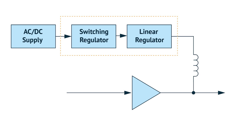
Table 1 shows a summary of the data sheet specifications of the power solutions used.
LTM8063 | LTM4626 | LT3045 | |
Topology | Buck µModule® | Buck µModule | LDO regulator |
Input Voltage Range | 3.2V to 40V | 3.1V to 20V | 1.8V to 20V |
Output Voltage Range | 0.8V to 15V | 0.6V to 5.5V | 0V to 15V |
Output Current | 2A | 12A | 500mA |
Noise | ~15mV ripple | ~35mV ripple | 1μV rms |
Switching Frequency | 200kHz to 2MHz | 600kHz to 2MHz | — |
Table 1: Specifications of LTM8063, LTM4626, and LT3045. Source: Analog Devices
The input signal swept the frequency range of 100MHz, 200MHz, 500MHz, and 1GHz to 10GHz. We analyzed phase noise with a frequency offset of 10Hz to 30MHz and noted the results in Table 2.
Table 2 shows a summary of the performance of two Analog Devices RF amplifier products employed to represent a block in the RF signal chain. Source: Analog Devices The HMC8411 and ADPA9002 are Gallium Arsenide (GaAs), Monolithic Microwave Integrated Circuit (MMIC), Pseudomorphic High Electron Mobility Transistors (pHEMT), low noise wideband amplifier that operates from 0.01 GHz to 10 GHz, and between DC and 10 GHz respectively.
HMC8411 | ADPA9002 | |
Frequency Range | 10MHz to 10GHz | DC to 10GHz |
VDD (typ.) | 5V | 12V |
IDD (typ.) | 56mA | 385mA |
Gain | 15.5dB | 15dB |
Output P1dB Compression (typ.) | 20dBm | 29dBm |
Table 2: Performance of HMC8411 and ADPA9002 GaAs MMIC pHEMT devices
Results
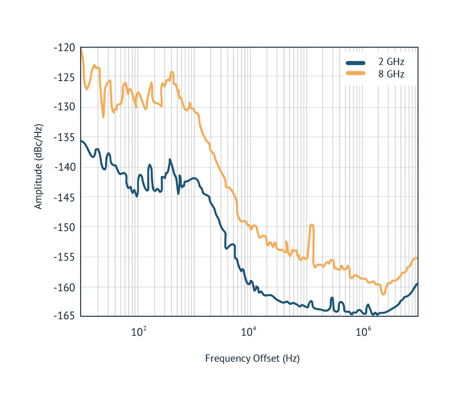
The Power Amplifier (PA) is observed to have slightly lower performance past 1/f frequencies. The PA draws substantially more supply current, resulting in roughly a 2dB to 4dB increase in observed phase noise as shown in Fig. 2(a), 2(b), and 3.
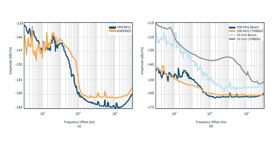
This relationship shows every doubling of the input frequency results in roughly a 6dB increase in phase noise. This can be seen with a 4X increase in frequency, results in approximately a 12dB increase from 10Hz to 100Hz frequency offset.
Bench supply phase noise response was used as a baseline to judge the performance of specific power solutions. The LTM8063 has exceptional performance across various frequencies compared to the bench supply, with only an approximate 2dB increase in the wideband noise floor as shown in Fig. 4.
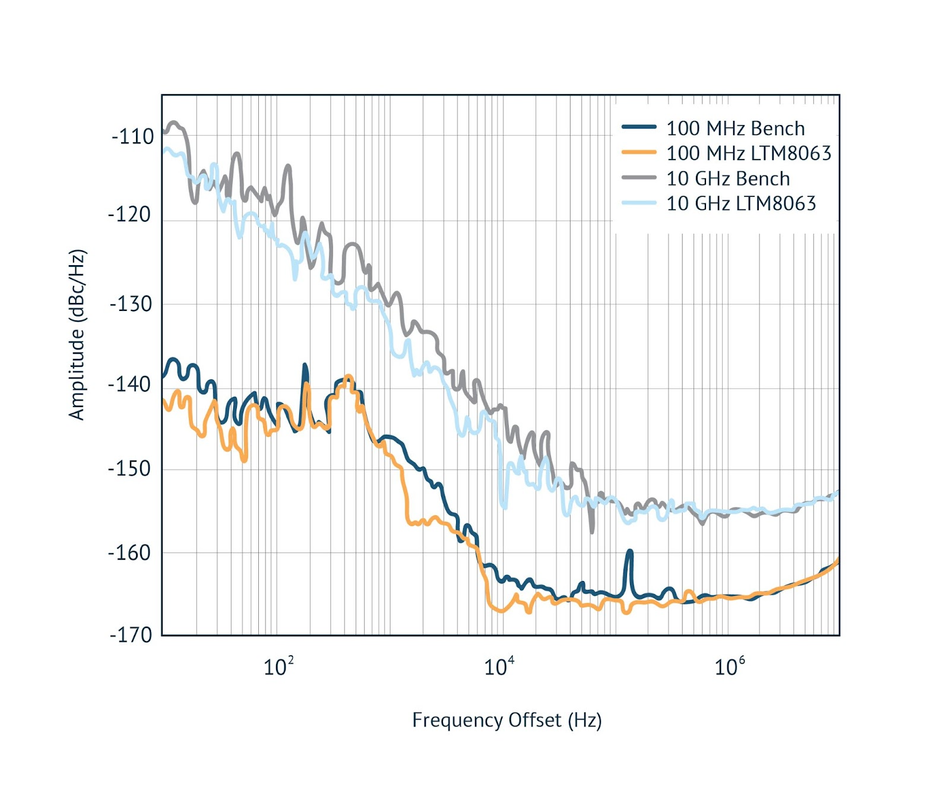
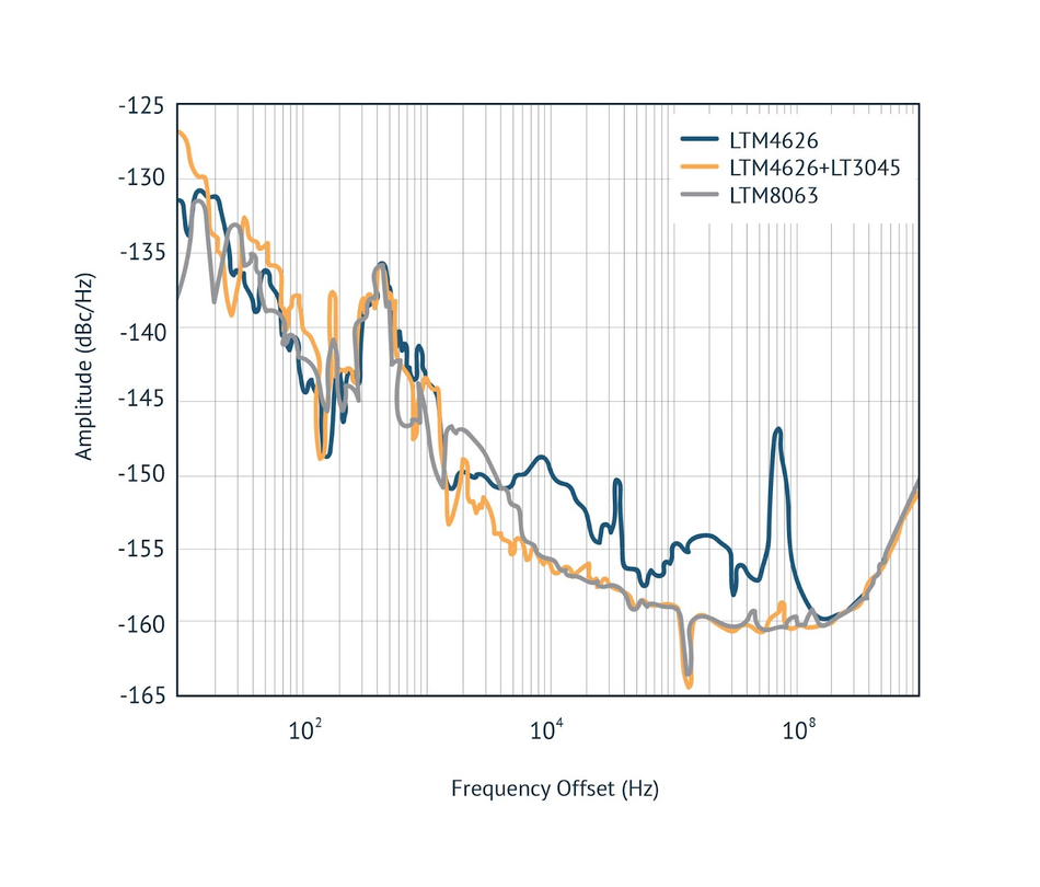
Commonly, a high-current module such as the LTM4626, will be used as the main supply so that the power distribution network can get stepped down according to each circuit block’s requirements. In this example, the LTM8063 exhibits similar phase noise performance to the LTM4626 cascaded with the LT3045 ultralow noise LDO regulator (Fig. 5). If the voltage and current output supplied by the LTM8063 can satisfy design requirements, this power solution can save considerable cost and board space.
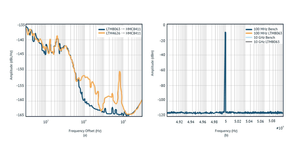
The switching power supplies exhibit markedly different behavior in various frequency bands as shown in Figure 6(a). The LTM8063 and LTM4626 have a similarly negligible impact on the power Low Noise Amplifier (LNA) phase noise below 5kHz but diverges significantly above that.
The LTM4626 was designed and optimized to power high-end digital products. These devices typically demand high efficiency and fast transient response. Their power supplies may have low passive impedance, fast switching edge rates, and increased control loop gain and bandwidth.
These features can create a few millivolts (mV) of perturbations in the output voltage. Though inconsequential in a digital system, these perturbations can degrade the performance of a signal chain product. Despite this, the output spectrum using the LTM4626 showed no noticeable spurs with a Spurious-Free Dynamic Range (SFDR) of 102.7dB as shown in Fig. 6(b).
The LTM8063, however, was designed for low noise—both Electromagnetic Interference (EMI) and output—optimizing its performance in signal chain applications. It exhibits excellent low-frequency stability, small output perturbations, and much less noise at the switching fundamental and its harmonics.
Conclusion
Considering all noise sources when performing a signal chain analysis is essential. One commonly overlooked source is the DC power solution, which can couple to and severely degrade the performance of the signal chain.
The results of our experiment show that proper choice of power modules is paramount and can lead to up to a 10dB improvement of phase noise at a 10kHz offset. For this application, the LTM8063 returned the best results. While the LTM4626 cascaded with the LT3045 gave comparable phase noise performance, knowing the correct power solution to choose is critical for optimizing the RF signal chain.
This article is based on an e-book by Mouser and Analog Devices. It has been substantially edited by the Wevolver team and Electrical Engineer Ravi Y Rao. It's the fourth article from the Power Management for Tomorrow’s Innovations Series. Future articles will introduce readers to some more power management and optimization techniques for modern electronic systems.
The introductory article covered the fundamentals of power electronics, the technology behind highly-efficient power conversion in different electrical/electronic systems.
The first article shares some design techniques for efficient power management in EVs. It covers how manufacturers can build significantly better vehicular electric power systems with systematic planning and innovative power electronic solutions.
The second article introduced readers to silent switching and how it prevents EMI at the source, rather than adding shields and filters to the product later.
The third article describes current measurement techniques using LTC297x series components by Analog Devices. It presents some application circuits and compares different approaches for current sensing in power electronic converters.
The fourth article discussed the problems associated with phase noise and experimentally showcased how power supply designs can be optimized to deal with them.
The fifth article featured Single-Inductor Multiple-Output architecture that integrates different power supply functionalities to drastically reduce the overall size and costs for wearables.
The sixth article describes how vehicular asset-tracking devices are powered with small, efficient power solutions and protected from electrical stresses.
The seventh article explains how designers can implement and validate proven power supply circuits for enabling the reliable operation of healthcare devices.
The final article dealt with a specific IoT power management solution for small, and portable gadgets. It showcases a nano-Power boost converter that ‘operates on fumes’ to make the most out of all the available energy.
About the sponsor: Mouser Electronics
Mouser Electronics is a worldwide leading authorized distributor of semiconductors and electronic components for over 1,100 manufacturer brands. They specialize in the rapid introduction of new products and technologies for design engineers and buyers. Their extensive product offering includes semiconductors, interconnects, passives, and electromechanical components.

References
[1] Mitchell Sternberg, Erkan Acar, David Ng, and Sydney Wells, ‘How to Select the Best Power Solution for RF Signal Chain Phase Noise Performance?’, Analog Devices, [Online], Available from: https://www.analog.com/en/technical-articles/how-to-select-the-best-power-solution.html, https://www.mouser.com/pdfDocs/A445251_select-the-best-power-solution-for-rf-signal-chain-phase-noise-performance.pdf