Power Supply Subsystems for Remote Patient Vital Sign Monitoring
Article #7 of Power Management for Tomorrow’s Innovations Series: Power supplies utilized in the medical industry must be compact, reliable, long-lasting, and robust.

24 Oct, 2022. 7 minutes read

Image credit: Masimo
This is the seventh article in an 8-part series featuring articles on Power Management for Tomorrow’s Innovations. The series focuses on power management and optimization techniques for modern electronic systems. This series is sponsored by Mouser Electronics. Through the sponsorship, Mouser Electronics shares its passion for technologies that enable smarter and connected applications.
While power supplies designed for medical equipment may not look different from the other commercially available ones, they are specially designed to offer high reliability and be compliant with different safety standards across the world. Medical products have to take accurate readings, fit in small spaces and go without replacement for long periods of time.
This article takes a look at how designers can implement and validate proven Switch-Mode Power Supply (SMPS) circuits for remote vital sign monitoring devices. References to Analog Devices’ pre-validated designs including biosensing Analog Front Ends (AFEs) and SMPS circuits will be made to practically explain the topic.
Components of a Power Supply for Remote Patient Vital Sign Monitoring Devices
Remote patient vital sign monitoring devices include wearables that keep a track of a person’s body temperature, pulse, blood pressure, respiration rate, oxygen levels, and more. These devices systematically monitor, store, and share data with healthcare service providers.
Medical wearables and remote patient vital sign monitoring devices include AFE circuits that are used to condition the signal coming from the sensor, a communication module for data sharing, a microcontroller for interfacing different subsystems, and a power circuit to fulfill the power requirements of the entire system.
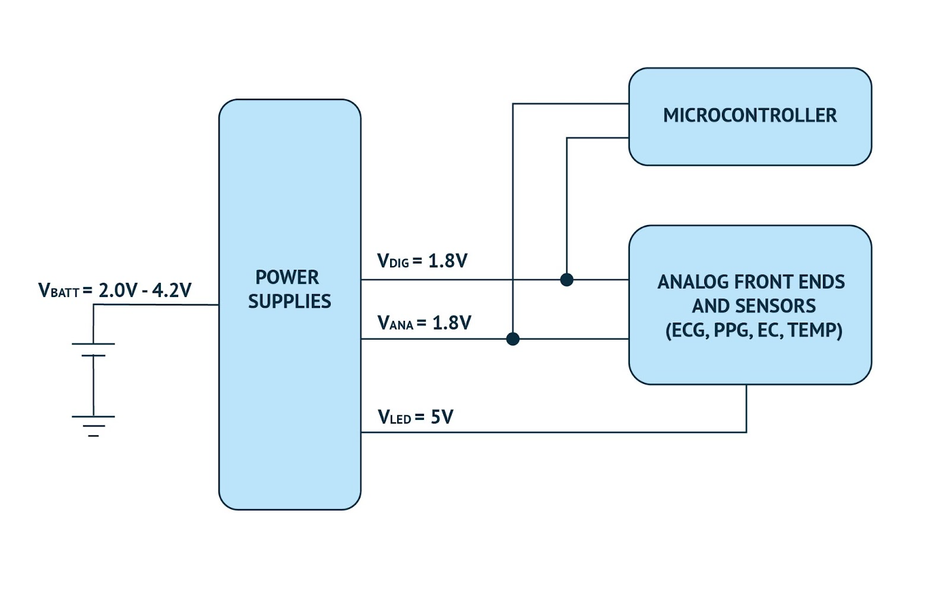
Fig. 1 shows a block diagram where various biosensing AFE devices require multiple power channels to power the digital, analog, and external Light Emitting Diodes (LEDs) supply.
Electronic manufacturers offer designers pre-validated power supply circuits for use with biosensing devices. In addition, each power supply circuit example is complemented with a validation checklist and troubleshooting guide to aid circuit designers if needed.
Battery Choices for Wearable Applications
Choosing the right battery for the wearable is critical as there it has a direct impact on the battery life, overall design size, cost, and ultimately–reliability. Common wearable battery types can be categorized into two basic groups:
Primary cell (non-rechargeable)
Secondary cell (rechargeable)
Examples of primary cell batteries include alkaline, lithium-ion (Li-ion), zinc-air, and silver-oxide varieties, whereas examples of secondary cell batteries include Li-ion and lithium polymer (LiPo or LiPoly) cells. Lithium-ion and lithium polymer batteries for wearable applications get favored due to size, mass, rechargeability, energy density, and eco-friendliness.
The designer should know that each battery type will have its own electrical characteristics (eg., voltage output level, energy storage level, charge/discharge behavior, etc.). Thus, an appropriate switch-mode power supply (SMPS) circuit will need to be implemented for each battery type. In addition, as newer battery types get deployed, the engineers will have to evaluate, characterize, and possibly re-design their power supply circuits accordingly.
AFEs and Power Electronic Converters by Analog Devices for Medical Applications
Retrieving actionable information from biosensor data requires excellent system signal-to-noise performance. Adopting high-performance AFEs is the first step toward this goal. The next step is to build a sound power supply design.
Pre-validated Solutions for Medical Product Design
Designers can develop remote patient vital sign monitors and consumable diagnostic devices using Analog Devices’ biosensing AFEs. Analog Devices’ pre-validated solutions apply to designs with the following requirements:
Small system form factor and low mass.
Maintains good battery life with low battery mass and cost. Most of the systems get kept in standby or low power state.
Very high signal-to-noise performance at sampling rates below 1kHz.
The design employs one or more (primary or secondary) batteries with a nominal voltage ranging from 0.9V to 4.2V. For example:
LP401230 3.7V 105mAh Secondary (Rechargeable) Cell LiPo Battery
BR2032 3.0V 190mAh Primary (Non-Rechargeable) Cell Battery
CR2032 3.0V 235mAh Primary (Non-rechargeable) Cell Li Battery
Includes devices that require one or more voltage rails, for example:
1.8V for digital devices (VDIG) with fast transitions and high operating current
1.8V analog supply (VANA) where power supply noise affects sensor data integrity
5V supply for LED currents (VLED) in optical systems
Analog Devices pre-validated solutions guide designers to:
Select a power supply configuration based on system requirements
Use reference circuits and layouts of both discrete and integrated designs
Adopt a power supply performance test methodology to validate the system over different device use cases and transient loading conditions
Utilize a comprehensive checklist to validate their implementation
View test data expected from a successful implementation
Apply system integration guidelines
Follow troubleshooting instructions to address issues
Table 1 summarizes some AFEs by Analog Devices available via suppliers like Mouser Electronics and their functions.
Analog Devices Part Number | Function |
MAX30001CWV+ | ECG, R-to-R, Pace, and BioZ Biosensor |
MAX30003CWV+ | Ultra-Low Power, Single-Channel Integrated Biopotential (ECG, R to R Detection) AFE |
MAX30004CWV+ | Ultra-Low Power, Single-Channel Integrated Biopotential HR Detection AFE |
MAX86140ENP+ | Optical Pulse Oximeter and Heart Rate Biosensor (MAX86140 Single Channel; MAX86141 Dual Channel) |
MAX86141ENP+ | |
MAX86176ENX+ | ECG, Optical Pulse Oximeter, and Heart Rate Biosensor |
MAX86131CWA+ | Electrochemical Biosensor |
MAX30208CLB+ | ±0.1°C Accurate, I2C Digital Temperature Sensor |
Table 1: Analog Devices AFEs and their functions
Remote Patient Monitor and Medical Wearable System Configurations
Analog Devices’ rechargeable power system configuration gets designed to work with input voltages ranging from 3.0V to 4.2V, typical of Li-ion or LiPo rechargeable batteries. Three outputs get generated: two 1.8V supplies (VANA and VDIG) and one 5V supply (VLED). Fig. 1 above showed a block diagram where one supply is a tightly regulated 1.8V digital supply to power the digital sections of a microcontroller where noise is typical with fast transitions of digital signals.
Analog Devices’ Switch-Mode Power Supply (DC-DC Converter) Circuits highlight operational details of known good reference designs, including:
Circuit description, including web links to applicable design files (schematic/Bill of Materials (BOM)/layout)
Validation checklist to confirm the implemented circuit function
Selecting test data plots highlighting secondary typical operating characteristics
Both discrete and integrated switch-mode power supply options get offered to help designers accommodate their specific PCB layout requirements.
DC-DC Converters for Maximum Reliability in Medical Applications
Analog Devices MAX3864xA/B nanoPower Buck Converters employ a unique control scheme that allows ultra-low quiescent current and high efficiency over a wide output current range. The MAX3864xA/B Converters feature an operating voltage of 1.8V to 5.5V while supporting load currents of up to 175mA, 350mA, and 700mA. Additional benefits of the series include a 330nA ultra-low quiescent supply current, a 5nA shutdown current, and 96% peak efficiency. The Buck Converters are excellent for battery applications where extended battery life is required.

Analog Devices MAX20343/MAX20344 Buck-Boost Regulators offer a 1A current capability at 3.5V intended for applications that require long run times while also demanding bursts of high current. The MAX20343/MAX20344 employs a unique control algorithm that seamlessly transitions between buck, buck-boost, and boost modes, minimizing discontinuities and subharmonics in the output voltage ripple. The MAX20343/MAX20344 features a low 1.9V input voltage for the startup that allows users to power the device from various sources. The MAX20343/MAX20344 design keeps inductance and output capacitance requirements as low as possible for space-constrained applications.

Conclusion
The purpose of power supplies in healthcare is to continuously feed energy to devices that assist doctors in treating and monitoring patients. These devices must comply with the highest standards of safety and reliability.
Pre-validated designs for AFEs and power electronic converters like the ones built by Analog Devices provide engineers with all the necessary tools and supporting documents required to build medical solutions that are compact, reliable, long-lasting, and robust.
Check out our recent series Improving Lives with Digital Healthcare to read more about how modern medical instruments like wearables, enhanced by the latest digital technologies, are making healthcare more accessible, personalized, and proactive.
This article is based on an e-book by Mouser and Analog Devices. It has been substantially edited by the Wevolver team and Electrical Engineer Ravi Y Rao. It's the seventh article from the Power Management for Tomorrow’s Innovations Series. Future articles will introduce readers to some more power management and optimization techniques for modern electronic systems.
The introductory article covered the fundamentals of power electronics, the technology behind highly-efficient power conversion in different electrical/electronic systems.
The first article shares some design techniques for efficient power management in EVs. It covers how manufacturers can build significantly better vehicular electric power systems with systematic planning and innovative power electronic solutions.
The second article introduced readers to silent switching and how it prevents EMI at the source, rather than adding shields and filters to the product later.
The third article describes current measurement techniques using LTC297x series components by Analog Devices. It presents some application circuits and compares different approaches for current sensing in power electronic converters.
The fourth article discussed the problems associated with phase noise and experimentally showcased how power supply designs can be optimized to deal with them.
The fifth article featured Single-Inductor Multiple-Output architecture that integrates different power supply functionalities to drastically reduce the overall size and costs for wearables.
The sixth article describes how vehicular asset-tracking devices are powered with small, efficient power solutions and protected from electrical stresses.
The seventh article explains how designers can implement and validate proven power supply circuits for enabling the reliable operation of healthcare devices.
The final article dealt with a specific IoT power management solution for small, and portable gadgets. It showcases a nano-Power boost converter that ‘operates on fumes’ to make the most out of all the available energy.
About the sponsor: Mouser Electronics
Mouser Electronics is a worldwide leading authorized distributor of semiconductors and electronic components for over 1,100 manufacturer brands. They specialize in the rapid introduction of new products and technologies for design engineers and buyers. Their extensive product offering includes semiconductors, interconnects, passives, and electromechanical components.

References
[1] Marc Smith, ‘Power Supply Subsystems for Vital Sign Monitors’, Analog Devices, [Online], Available from: https://pdfserv.maximintegrated.com/en/an/an7459-power-supply-subsystems-for-vital-sign-monitors.pdf, https://www.mouser.com/pdfDocs/an7459-power-supply-subsystems-for-vital-sign-monitors.pdf