SCCR Rating: How to Determine, Raise, and Mark It
This article is a practical reference for establishing the SCCR rating of an industrial control panel, from the weakest-link method in UL 508A Supplement SB through the marking the inspector will look for.

28 Oct, 2026. 15 minutes read
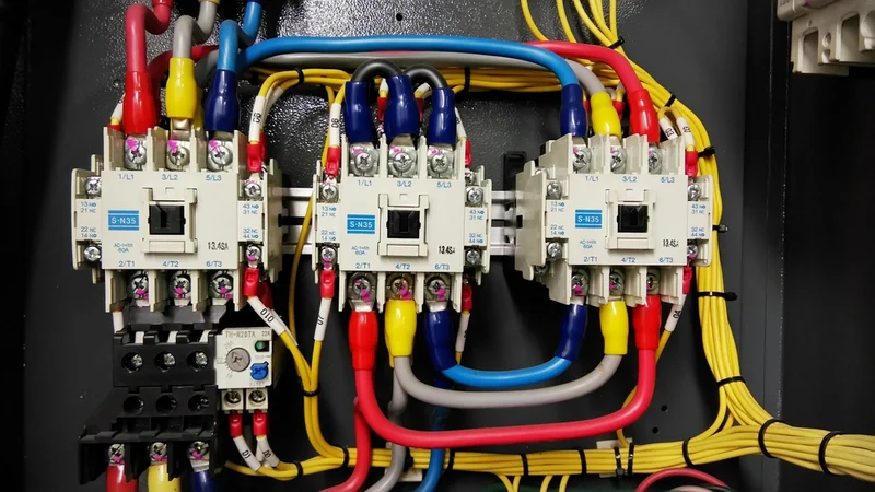
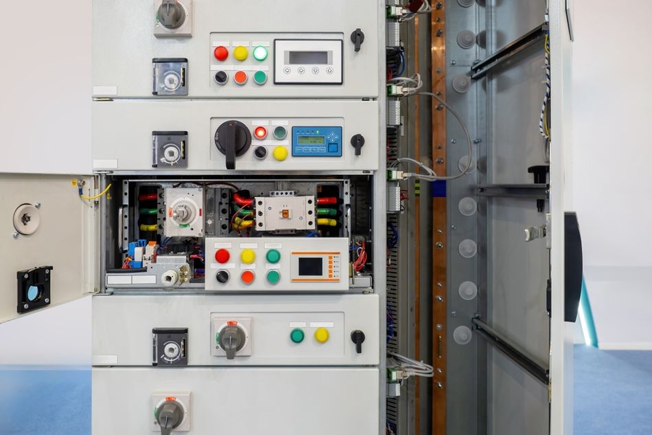
Industrial Electrical Control Panel with Contactors, Circuit Components, and Colored Wiring, Labels
Key Takeaways
SCCR vs. Available Fault Current – SCCR is an equipment assembly rating specifying the maximum fault current a panel can safely withstand; available fault current is a property of the supply grid, and the panel's rating must meet or exceed it.
Assembly Rating vs. Component AIC – Interrupting rating (AIC) applies to individual overcurrent protective devices under NEC 110.9, whereas short-circuit current rating (SCCR) applies to the complete integrated panel assembly under NEC 110.10.
Weakest-Link SB Methodology – UL 508A Supplement SB establishes the panel SCCR based on its lowest-rated component, meaning a single unmarked contactor or overload relay can reduce an otherwise 65 kA panel down to a 5 kA default rating.
Current-Limiting Fuse Mitigation – Integrating current-limiting fuses or circuit breakers into the main feeder circuit raises overall panel SCCR by capping peak let-through current below the downstream branch component ratings.
SCCR Calculation and Verification Steps – Calculating panel SCCR requires identifying individual component ratings, checking high-fault combination series ratings, applying feeder current-limiting devices, and documenting the final rating on the schematic.
NEC Nameplate Compliance – NEC Article 409 mandates marking the calculated short-circuit current rating directly on the industrial control panel nameplate, though panels containing only control-circuit components are exempt from this requirement.
Introduction
SCCR rating decides whether a panel may legally be installed at a given point in the distribution system of a plant. If you get it wrong and the panel either fails inspection or, worse, sits in service unable to survive a fault it will eventually see.
Despite its importance, SCCR rating is among the most commonly misunderstood figures in industrial control panel design. It is routinely confused with interrupting rating, often called AIC, and available fault current. Understanding these distinctions is essential when selecting components, evaluating a panel, or planning an upgrade.
This article explains how UL 508A Supplement SB establishes the SCCR rating, why so many panels end up at 5 kA, and which design changes can raise that limit. It also covers how to mark the SCCR rating so installers and inspectors can verify the panel’s suitability for its intended location.
What an SCCR Rating Is?
The National Electrical Code defines short-circuit current rating as "the prospective symmetrical fault current at a nominal voltage to which an apparatus or system is able to be connected without sustaining damage exceeding defined acceptance criteria". [4]
UL 508A carries a closely matching definition in its own Chapter 2.44, wording it as "the fault current at a nominal voltage to which an apparatus or system is able to be connected without sustaining damage exceeding the defined acceptance criteria". [2]
Here, two things follow from that wording. The rating belongs to equipment, not to the supply, and it is a withstand rating rather than a promise to clear anything. One code trainer puts it, the SCCR "is the equipment's ability to withstand high levels of current", while available fault current "is NOT an equipment rating". [6]
Article 409 of the NEC covers industrial control panels at and under 1000 V, a scope that previously stopped at 600 V, and the third edition of UL 508A reflects the same change. Everything below sits inside that scope.
SCCR vs AIC vs Available Fault Current
Understanding the difference between SCCR, interrupting rating, and available fault current is essential when evaluating an industrial control panel. Each describes a different aspect of short-circuit performance, and you can't use them interchangeably.
Available Fault Current describes the largest current the electrical supply can deliver at a particular point during a short circuit. It is a characteristic of the electrical system, not an equipment rating. Fault current describes the current delivered during a fault, while available fault current describes the maximum that could be delivered. Article 100 provides these definitions. [4]
Interrupting Rating, commonly called AIC (Ampere Interrupting Capacity), describes the current a protective device can safely interrupt at a specified voltage. NEC 110.9 requires equipment intended to interrupt fault current to have an interrupting rating at least equal to the current available at its line terminals, at nominal circuit voltage. [4] AIC is common industry shorthand, not the terminology used by the code.
Short-Circuit Current Rating (SCCR) describes the prospective fault current an assembly or component can withstand under specified conditions without damage exceeding the applicable acceptance criteria. NEC 110.10 addresses equipment short-circuit performance, while 409.110 covers SCCR marking for industrial control panels. [3][5]
The practical mistake is assuming that a protective device’s interrupting rating establishes the SCCR of the entire panel. It does not. A fuse may safely interrupt a high fault current, but that alone does not establish whether the terminal blocks, contactors, and other components it protects meet their applicable short-circuit acceptance criteria.
Terminology can add to the confusion. Expressions such as maximum fault current and available short-circuit current describe supply-side fault-current quantities rather than equipment capability. [6] Once reviewing a design, distinguish the current the system can supply from the current a protective device can interrupt and the fault-current level an assembly is rated to withstand.
Recommended Reading: Engineering for Transient Resilience
Where the Code Requires an SCCR Rating?
NEC 110.10 is why the rating exists. The code in question is NFPA 70, published as the National Electrical Code. [2] That section requires that overcurrent protective devices and component SCCRs "shall be so selected and coordinated to permit the circuit protective devices used to clear a fault to do so without extensive damage to the electrical components of the circuit". [3]

In practice, this means an industrial control panel must have an SCCR equal to or greater than the available fault current of the system where it is installed. The marking exists so that this can be checked at installation and again if the panel is ever relocated.
| Requirement | What it Obliges? |
| NEC 110.10 | The equipment SCCR must be equal to or greater than the available fault current at the installation point. |
| NEC 409.110 | The industrial control panel must be marked with its assembly short-circuit current rating, plainly visible after installation. |
| NEC 409.22 | Document the available fault current feeding the panel and the date of that calculation. |
| NEC 670.5(2) | Field marking of industrial machinery with the short-circuit current calculation date and the maximum available fault current. |
| NEC 408.6 | "Switchboards, Switchgear, and Panelboards shall have a short-circuit current rating (SCCR) not less than the available fault current". |
| NFPA 79 Clause 16.4 | Nameplate on industrial machinery carrying the short-circuit current rating. |
Article 409 also names its own escape hatch: an industrial control panel containing only control circuit components does not need an SCCR rating. Article 409 references UL 508A Supplement SB4 in an informational note as an approved method of calculating the rating of a panel. [2]
How to Determine the Available Fault Current at the Panel?
Determining the available fault current requires a short-circuit calculation for the panel’s installation point. Start with the supply characteristics, then account for the transformers, conductors, and other sources that affect how much current can reach a fault.
First, obtain the utility’s available fault current at the service point, or use an existing short-circuit study that accurately represents the installation. Record the supply voltage and system configuration so the calculation follows the actual electrical path to the panel.
Next, establish the transformer and feeder characteristics. Transformer kVA, secondary voltage, and percentage impedance affect the fault current available at its secondary terminals. Conductors between the transformer and panel add impedance, so include their length, size, material, and parallel arrangement. Eaton’s point-to-point method accounts for these factors when calculating fault current at successive locations in a distribution system.
Include contributions from motors and other connected sources. Running motors can briefly feed current into a short circuit. Where generators or multiple supplies are present, the study must account for the operating configurations that produce the maximum available fault current. A transformer-only estimate may therefore be insufficient for the panel location.
Finally, compare the calculated available RMS symmetrical fault current with the panel’s marked SCCR at the applicable voltage. For example, a panel rated 65 kA at 480 V can satisfy the fault-current comparison where 40 kA is available, provided the installation meets the conditions supporting that rating. A 10 kA panel cannot satisfy the same comparison.
Keep the calculation inputs, results, and calculation date with the installation records. Reassess the comparison when changes to the supply, transformer, feeder, or panel location could alter the available fault current.
Recommended Reading: Terminal Block Selection: Types, Ratings, and Wiring
How to Calculate SCCR Under UL 508A Supplement SB?
The UL 508A standard, formally the Standard for Industrial Control Panels, is now in its third edition, dated 24 April 2018. Supplement SB covers the rating.

There are two accepted routes to a panel rating. First, you can test the assembled panel to a standard with a third party witness such as Underwriters Laboratories, which suits simple panels built in volume, or you can use UL 508A Supplement SB, which lets the panel manufacturer assign a rating without testing the assembly. [3]
The second route is what most panel shops use because, for "low volume or one-of-a-kind panels", testing the assembled panel would be prohibitive. It is commonly called the weakest link approach: the panel SCCR is limited to the SCCR of the lowest rated component or the lowest rated branch circuit protective device in the panel.
The SCCR calculation runs in four steps:
Step 1: Rate Every Power Circuit Component
Power circuits are every circuit in the panel except control circuits. The feeder circuit supplies power to the supply side of the branch-circuit overcurrent device, and the branch circuit runs from that overcurrent protection device to the load.
UL 508A requires all power components to carry short-circuit current ratings, except power transformers, reactors, current transformers, dry-type capacitors, resistors, varistors, and voltmeters. [3] Rockwell's guidance names voltmeters, EMI filters and power resistors as examples of exempt parts, and notes that a one-port surge protection device does not need an SCCR either.
There are three ways to establish a component's rating: the manufacturer's tested rating from the label or instruction sheet, the manufacturer's product test data, or the default values in Table SB4.1 where the device is not marked and no data is provided. The third route is very conservative. [2]
Step 2: Account for Current-Limiting Devices
This is where a low component rating stops being fatal. Considering the current-limiting effect of an upstream device allows higher panel ratings, on three conditions. [3]
The upstream overcurrent protective device must be a UL Class CC, G, J, L, RK1, RK5 or T fuse, or a listed circuit breaker marked "current-limiting". [3] Under SB4.3.3, the short-circuit current on the line side of that feeder fuse cannot exceed the branch device's interrupting rating or combination controller rating.
That current-limiting fuse or circuit breaker must sit in the feeder circuit position rather than the branch circuit, and must be inside the panel.
The peak let-through current passed by the feeder device must not exceed the SCCR of the protected component.
The peak let-through current is "the maximum instantaneous current passed by a current limiting fuse when clearing a fault current of a specified magnitude". UL 508A Table SB4.2 tabulates it by fuse class and ampere rating: a 60 A Class J fuse, for instance, has a peak let-through of no more than 10 kA for available short circuit currents up to 100 kA. [3]
The circuit breakers work differently. UL 508A publishes no equivalent let-through table because UL 489 does not specify maximum allowable let-through values for current-limiting breakers, whereas the UL 248 fuse standards do specify maximum acceptable values at 50 kA, 100 kA, and 200 kA. For breakers, consult the manufacturer's let-through curves for the specific device. [2]
The example shared by Rockwell shows how much this matters. With 65 kA available and a current-limiting feeder breaker holding peak let-through to 22 kA, a motor controller rated only 25 kA is acceptable, and the branch circuit breaker then sets the result: a 65 kA branch breaker yields a 65 kA panel, while a 35 kA branch breaker yields 35 kA, even with a 100 kA feeder breaker ahead of it. [2]
Step 3: Assign the Overall Panel Rating
For a single branch circuit with branch circuit protection, SB4.4.1 takes the smallest rating among the load-side power circuit components and compares it with the rating of the branch circuit protective device, assigning the smaller of the two to the line side of that device.
Where a panel has multiple branch circuits and feeder components, the overall rating is the lowest of three values: the lowest branch circuit rating not modified by the current-limiting rules, the SCCR of any feeder component not otherwise covered, and the modified rating determined for each branch circuit fed by the associated feeder component.
Step 4: Mark the Panel
Under SB5.1, every industrial control panel nameplate must show the SCCR and maximum voltage. Rockwell's example label reserves a field reading "panel short circuit rating [kA rms sym.]", and shows a panel marked 65 kA installed where 40 kA is available. [2]
But, two marking subtleties catch people out. The panel needing a field-installed branch-circuit protective device must be marked with the required size and type, and a panel marked with a high-fault rating but supplied without feeder-circuit protection must state the type and size of the field-installed feeder protection its rating depends on.
Recommended Reading: UL 508A: The Standard for Industrial Control Panels
Why Do So Many Panels Come Out at 5 kA?
If a power circuit component carries no marked short-circuit current rating, Supplement SB does not let you ignore it. Table SB4.1 assigns an assumed rating, and several common component types default to just 5 kA.

In the historical Table SB4.1 values reproduced by Mersen, effective 25 April 2006, circuit breakers, overload relays, switches other than mercury tube types, switch units, and motor controllers rated up to 50 hp all receive an assumed SCCR of 5 kA. The otherwise highly rated panel can therefore end up with a low SCCR because of a single motor branch. [3]
Some defaults are even lower. Supplementary protectors receive an assumed rating of 0.2 kA, while GFCI receptacles receive 2 kA. Busbars, terminal blocks, power distribution blocks, fuseholders, and non-GFCI receptacles receive 10 kA. For larger motor controllers, the assumed ratings increase to 10 kA for 51–200 hp, 18 kA for 201–400 hp, and 30 kA for 401–600 hp. [3]
These historical values illustrate the impact of relying on defaults; they should not replace verification against the applicable edition of UL 508A. Tables can change between editions. Rockwell, for example, notes that the companion transformer table SB4.4 was updated with lower values than earlier versions.
Rockwell’s example panel shows the practical consequence. Its main breaker has a manufacturer rating of 65 kA, and three of its four motor branches have manufacturer combination ratings of 65 kA. However, the circuit breaker, contactor, and overload relay in the remaining branch fall back to their 5 kA defaults. The resulting panel marking is 5 kA at 480 V AC, despite the higher ratings elsewhere in the assembly. [2]
Whether that rating is adequate depends on the available fault current at the installation point. Mersen illustrates how a 2,500 kVA transformer with a 480 V secondary, supplied by a utility with a primary short-circuit capability of 250 MVA, can produce secondary fault current approaching 60 kA when motor contribution is included. [3] A 5 kA or 10 kA panel would be inadequate at that location. The installation’s available fault current, rather than a general assumption about industrial facilities, determines the required rating.
Recommended Reading: Future Trends in Control Panels
How to Raise a Low SCCR?
Here, three strategies do the work, and they combine.
Upgrade the Weak Components: In Mersen's example panel, swapping a 5 kA motor starter for one marked 10 kA lifts that branch to a modified 100 kA once you account for the current-limiting feeder fuses. The weakest link then moves to a 20 A molded case circuit breaker in the same branch, and the panel rating becomes 65 kA. [3]
Use Type-Tested Components: UL 508 lets component manufacturers test a device with specific overcurrent protective devices at higher levels to establish what UL calls high fault short circuit current ratings, a process called type-testing. Rather than accept the Table SB4.1 minimum, ask the manufacturer whether a higher rating exists for the device-and-protection combination you are using. Replacing the 5 kA starter with one tested at 100 kA with 15 A Class CC fuses, and the 20 A breaker with Class CC fuses rated 15 A or less, eliminates both weak links and allows a 100 kA panel. [3]
Exploit Current Limitation: Class J and Class CC time-delay fuses are chosen for their high degree of current limitation, and designers using RK5 fuses or devices that are not current-limiting may unnecessarily restrict the panel rating. [3]
Do not overlook the control circuit. Its SCCR equals the interrupting rating of the overcurrent protective device protecting it under SB3.2, so a low-rated control circuit device can cap the whole panel. Protecting the control circuit with Class CC time-delay fuses allows a 200 kA rating and removes that weak link.
For reference, a panel with a 100 kA SCCR suits virtually all industrial and commercial installations. [3] Ratings you will commonly meet on nameplates run 5, 10, 25, 35, 65, 100 and 200 kA, the values that recur across the worked examples above.
Recommended Reading: Open Circuit vs Short Circuit: Core Differences between Open and Closed Circuit
SCCR for Industrial Machinery
Machinery adds a wrinkle. Once determining the rating for UL Listed industrial machinery, UL 508A Supplement SB is the method used, while NFPA 79 is the standard for designing and building the machine. [1]
The available fault current at the line terminals of each machine supply circuit disconnecting means must be known to establish whether the panel containing that disconnect has an adequate rating, and a machine may have more than one source of supply. Where a machine has several panels, all panels used to provide control for that machine must be provided with a short-circuit current rating. [1]
The series ratings are worth knowing as a field-applied option. The circuit breaker can be used where available fault current exceeds its marked interrupting rating if it is connected on the load side of an acceptable overcurrent protective device with a higher rating. [1]
Recommended Reading: NFPA 79: The Electrical Standard for Industrial Machinery
How This Differs Outside North America
If you build for both markets, the concepts map, but the arithmetic does not. IEC 61439-1:2020 defines rated conditional short-circuit current Icc as the "value of the prospective short-circuit current, declared by the assembly manufacturer, that can be withstood for the total operating time (clearing time) of the SCPD under specified conditions". [7]
That is recognizably the same idea as SCCR, and the same source is explicit that despite being the same concept, "the way to calculate the SCCR is quite different between IEC and North America". The Icc declaration does not transfer to a UL 508A nameplate.
Common Mistakes and Troubleshooting
Reading the main breaker as the panel rating. The interrupting rating of the device protecting a circuit is not the short-circuit rating of that circuit. [5] The 65 kA main breaker on a panel full of 5 kA defaults still gives a 5 kA panel. [2]
Putting the current-limiting fuse in the wrong place. The current-limiting device must be in the feeder circuit, not the branch circuit, and inside the panel, or you can't claim its limiting effect.
Assuming a breaker limits current like a fuse. There is no UL 508A let-through table for breakers, and performance varies by manufacturer, so the specific device's curves must be checked. [2][3]
Forgetting the control circuit. The control-circuit rating is set by its protective device and can quietly cap the assembly.
Treating the rating as permanent. Changes to the power system change fault levels, and a panel moved to another part of the plant may face a different available fault current.
Assuming the calculation settles the matter. UL inspector or the authority having jurisdiction has the final ruling on code interpretation.
Conclusion
SCCR rating is the panel's license to be installed where you intend to install it. The method is not difficult, but it is unforgiving: Supplement SB reduces an assembly to its weakest link, and unmarked components bring severe defaults with them.
Specify components with marked or type-tested ratings, place current-limiting fuses in the feeder circuit where they can do useful work, check the control circuit, and mark the nameplate with the rating and voltage. Then confirm the figure against the available fault current where the panel will actually live, and document the SCCR calculation with the date it was performed.
Frequently Asked Questions
Q. Is an SCCR the same as an AIC rating?
A. No. "AIC" is industry shorthand for a device's interrupting rating, which NEC 110.9 applies to equipment intended to interrupt fault current. SCCR applies to a whole assembly or component under NEC 110.10 and describes withstand, not interruption. Assuming the protective device's interrupting rating represents the rating of the entire circuit is a documented and common error.
Q. How do you calculate an SCCR rating?
A. Follow UL 508A Supplement SB in four steps: establish each power circuit component's rating under SB4.2, modify the available current for current-limiting components under SB4.3, determine the overall panel rating under SB4.4, and mark the panel under SB5.1. The overall result follows the weakest link in the power circuit.
Q. What is a 5000 SCCR rating?
A. 5000 A is 5 kA, and it is usually not a designed figure but a default. In the 2006-era Table SB4.1 reproduced above, 5 kA is the assumed rating for unmarked circuit breakers, overload relays, switches and motor controllers up to 37.3 kW, so a single unmarked device can produce a 5 kA panel. Check the current edition for the values that apply to your build.
Q. Is a higher SCCR always better?
A. Higher gives you margin and flexibility, since fault levels change as the power system changes and panels get relocated. What matters for compliance is only that the rating is equal to or greater than the available fault current at the installation point. The 100 kA rating covers virtually all industrial and commercial installations.
Q. Does every industrial control panel need an SCCR marking?
A. Almost. Article 409 states that a panel containing only control circuit components does not need an SCCR rating. Any panel with a power circuit does, and it must be marked so it is plainly visible after installation.
Q. What happens if the panel's SCCR is lower than the available fault current?
A. It does not comply with NEC 110.10, which requires the rating to be equal to or greater than the available fault current where the panel is installed. The fix is either to raise the panel's rating or to reduce the available fault current reaching it.
References
[1] UL Solutions. Determining Short-Circuit Current Rating (SCCR) for Machinery [Cited 2026 October 27] Available at: Link
[2] Rockwell Automation. Short-circuit Current Ratings and Your Industrial Control Panel [Cited 2026 October 27] Available at: Link
[3] Mersen. Achieving Higher Short Circuit Current Ratings for Industrial Control Panels [Cited 2026 October 27] Available at: Link
[4] IAEI Magazine. Fault Current, or Short-Circuit Current, that is The Question [Cited 2026 October 27] Available at: Link
[5] IAEI Magazine. New Short-Circuit Current Rating Requirements Facilitate Compliance with 110.10 [Cited 2026 October 27] Available at: Link
[6] JADE Learning. Short-Circuit Current-Rating (SCCR) vs. Available Fault Current [Cited 2026 October 27] Available at: Link
[7] GT Engineering. Short-Circuit Aspects: NEC vs IEC [Cited 2026 October 27] Available at: Link
in this article
1. Key Takeaways2. Introduction3. What an SCCR Rating Is?4. SCCR vs AIC vs Available Fault Current5. Where the Code Requires an SCCR Rating?6. How to Determine the Available Fault Current at the Panel?7. How to Calculate SCCR Under UL 508A Supplement SB?8. Why Do So Many Panels Come Out at 5 kA?9. How to Raise a Low SCCR?10. SCCR for Industrial Machinery11. How This Differs Outside North America12. Common Mistakes and Troubleshooting13. Conclusion14. Frequently Asked Questions15. References