How to Test a Relay: Comprehensive Engineering Guide
Design engineers, hardware integrators, and automotive technicians frequently need to verify whether relays are healthy or need replacement. This article provides a thorough, step-by-step approach to testing relays while explaining the underlying science and standards.

03 Apr, 2026. 12 minutes read
Key Takeaways
Relays isolate control circuits from high-current loads. Mechanical relays rely on an electromagnetic coil and movable contacts, whereas solid-state relays use semiconductor devices.
Use a multimeter to measure coil resistance between the coil pins; typical values range from tens of ohms for automotive power relays to thousands of ohms for reed and solid-state relays.
Energise the coil with a controlled power source and listen for a firm click. Measure continuity between the common terminal and the normally open or normally closed contacts using a multimeter.
For critical applications, measure contact resistance using a micro-ohmmeter or the 6 V/1 A method. New automotive relays often show contact resistance below 50 milliohms. Rising or unstable resistance can indicate wear or contamination.
Always disconnect power before testing, use appropriate personal protective equipment, and verify the relay's rated coil voltage before applying any power.
Automotive systems, industrial PLCs, safety relays, and solid-state relays each require tailored test procedures.
Introduction
Relays are ubiquitous in electronic and electrical systems because they allow a low-power control signal to actuate high-power loads while maintaining galvanic isolation. Modern vehicles use relays to operate fuel pumps, cooling fans, starter motors, and climate-control compressors. Industrial machinery depends on interlock relays, safety relays, and PLC plug-in relays to sequence motors and protect workers.
Because relays undergo mechanical wear and may suffer from coil failures, burnt contacts, or contamination, engineers and technicians routinely test them to ensure reliability.
This article delivers an authoritative guide on how to test a relay. It explains relay theory, details the required tools, and provides step-by-step test procedures covering coil resistance measurement, continuity checks, contact resistance measurements, and specialised tests for automotive and industrial contexts. Failure modes and troubleshooting strategies are discussed, along with guidance for testing solid-state relays.
Fundamentals of Relays
Electromechanical relays consist of an electromagnetic coil that actuates one or more sets of movable contacts. When current flows through the coil, a magnetic field pulls a metal armature to close or open contacts.
Types of Relay and their Characteristics
Relays have various types which dictate their purpose of use. The following table elaborates the different types of relays and their distinctive features.
Relay Type | Typical Coil Resistance and Current | Notes |
Electromechanical power relay | Hundreds to thousands of ohms with coil currents around 40 mA. A 12 V automotive relay typically draws 150 to 200 mA with a gcoil resistance of approximately 80 to 60 ohms. | Uses an iron core and spring to move contacts. Suitable for automotive, industrial controls, and power distribution. |
Reed relay | Coil resistance around 2.4 kilohms, coil current around 10 mA. | Utilises hermetically sealed reed contacts. Offers fast switching and low contact bounce but limited current capability (500 mA or less). |
Solid-state relay (SSR) | Input "coil" equivalent is an LED; input resistance is typically thousands of ohms. Output uses MOSFETs or triacs with an on-state voltage drop of less than 2 V. | No moving parts; provides infinite mechanical life and fast switching. Leakage current and on-state voltage drop must be considered. |
Safety/industrial relays | Coil resistance ranges widely (75 to 225 ohms) depending on rated load; initial contact resistance is as low as 3 to 4 milliohms. | Designed for high reliability and compliance with safety standards. Often include mechanical indicators and test buttons. |
Coil Voltage and Resistance Fundamentals
Nominal voltage: The voltage at which the relay is designed to operate reliably. Many automotive relays use 12 V DC; industrial relays may use 24 V or 120 V.
Turn-on voltage (max): Minimum voltage needed to energise the coil. For a 12 V relay, the coil typically energises around 9 V.
Turn-off voltage (min): Voltage below which the coil releases. A 12 V relay often releases around 1.2 V.
Maximum coil voltage: Highest voltage allowed without overheating, often approximately 20 V for a 12 V relay.
Use Ohm's law (R = V/I) to calculate coil current. For example, a relay rated 12 V with 80 ohm coil resistance draws about 150 mA.
Contact Arrangements and Pin Functions
The contact arrangements on a relay are defined under the DIN72552 standard. It is a universal numbering system that ensures consistency, specifically for automotive and industrial applications. It is important to remember that the numbers don’t represent pin positions. Instead, they represent the functionality of the pins for consistency.
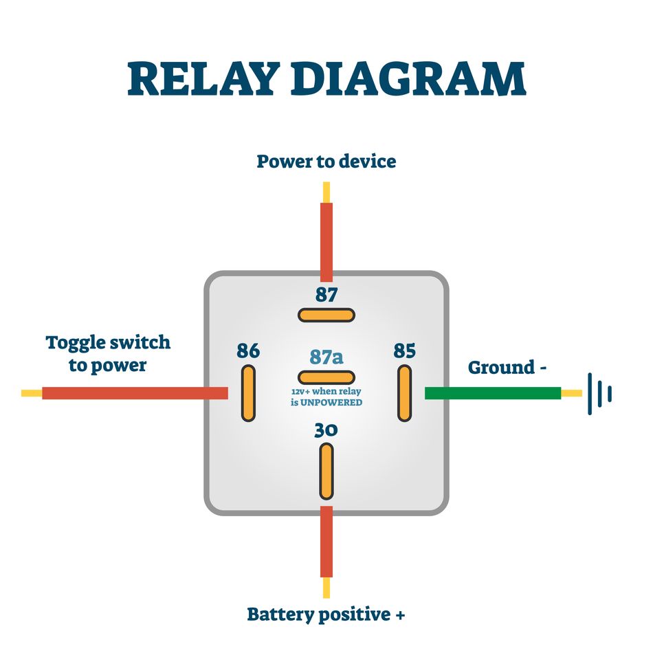
The following table summarizes the pin numbers and their functions.
Pin | Function | Wiring Scheme |
85 | Coil terminal (often connected to the negative terminal) | Connect to the ground or the negative side of the power source |
86 | Coil terminal (positive) | Connect to the positive control voltage |
30 | Common terminal | Connects to the load; switches between pins 87 and 87a |
87 | Normally open output | Connected to 30 only when the coil is energised |
87a | Normally closed output (not present on 4-pin relays) | Connected to 30 when the coil is not energised |
Recommended Reading: What is a Relay? Theory, Types, and Practical Implementation for Engineers
Tools and Safety Considerations for Relay Testing
Since relays are purely electrical devices, their testing equipment and tools must strictly ensure safety. As an engineer, you can test your relay with the following tools and equipment.
Tool | Purpose |
Digital multimeter (DMM) | Measures resistance (ohms), voltage, and continuity. Used to measure coil resistance and verify contact continuity. |
Micro-ohmmeter or milliohm meter | Provides accurate contact resistance measurement in the milliohm range using a four-wire (Kelvin) method. |
Bench power supply or automotive battery | Energises the relay coil at its rated voltage. |
Alligator clip leads and test leads | Secure connections to relay terminals. |
Insulation resistance tester (megohmmeter) | Measures resistance between coil and contacts to confirm insulation integrity. |
Oscilloscope (optional) | Observes operating and release times, contact bounce and chatter. |
Suggested Reading: How to Use a Multimeter: Engineering-Grade Techniques for Accurate Measurements
Safety Guidelines
Like with most electrical devices, there is a risk of electric shocks while working with relays. Here are a few considerations to ensure safety.
Safety Measure | Action | Advantage |
Disconnect power before removing or testing a relay in-circuit | Turn off and isolate the power supply before touching or removing the relay from the circuit. | Prevents electric shock, avoids arcing, and ensures safe handling and accurate testing. |
Verify voltage ratings | Check the relay’s nominal coil voltage and ensure the supply voltage matches it before energizing. | Prevents overheating, malfunction, and permanent damage to the relay. |
Use proper PPE | Wear safety glasses and insulated gloves while working with electrical circuits. | Protects against electric shock, sparks, and physical injury. |
Avoid short circuits | Carefully inspect wiring and double-check alligator clip connections before applying power. | Prevents current surges, equipment damage, and fire hazards. |
Respect stored energy (use suppression diodes) | Install a flyback diode across the relay coil to handle voltage spikes during switching. | Protects components from inductive kickback and reduces multimeter electrical noise in the circuit. |
Suggested Reading: Contactor vs Relay: Understanding the Differences and Applications
Step-by-Step Relay Testing Procedures
Testing a relay is a sequential procedure. While the steps may seem like a routine procedure for technicians and engineers, it’s critical to ensure the sequence for effective testing.
Step 1: Visual Inspection
Examine the relay for melted housing, burn marks, cracks, corrosion or discoloured plastic. If severe damage is visible, replace the relay. Usually, relays working for longer durations tend to wear out. Such devices are best replaced to avoid further malfunctions.
Step 2: Identify Relay Pins and Wiring Diagram
Consult the wiring diagram printed on the relay case or the datasheet. Match pin numbers with their functions. Relay contacts are marked with Normally Open (NO) and Normally Closed (NC) labels to ease testing. Make sure to read the markings before starting with the measurements.
Step 3: Measure Coil Resistance
Use a DMM to measure the resistance of the coils. Set the multimeter to resistance (ohms) mode. Connect one probe to pin 85 and the other to pin 86. You may observe the following typical results:
Automotive power relays: coil resistance between 50 and 200 ohms. Many 12 V power relays measure around 80 to 110 ohms.
Reed relays: coil resistance around 2 kilohms.
An open coil will show an infinite or "OL" reading; a shorted coil will show near-zero ohms.
Step 4: Apply Power and Listen for a Click
Connect the positive lead to pin 86 and the negative lead to pin 85. Now, momentarily energise the coil and listen for a distinct click. This click indicates that the armature has moved and the contacts have switched.
If you don’t hear a click, it indicates that the supply voltage meets or exceeds the turn-on voltage (usually 70% of nominal).
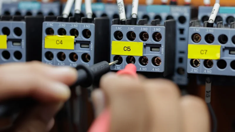
Step 5: Check Contact Continuity
With the relay de-energised, set the DMM to continuity mode:
30 to 87a: Should beep (closed circuit)
30 to 87: Should show no continuity (open)
Then energise the coil and repeat:
30 to 87: Should show continuity
30 to 87a: Should now be open
Step 6: Measure Contact Resistance
Set the DMM to a low-resistance range and measure resistance between pins 30 and 87 with the coil energised. A good automotive relay should measure less than 100 milliohms; high-quality relays specify an initial contact resistance of 3 to 4 milliohms.
For critical applications, use a micro-ohmmeter or the 6 V/1 A method that applies a known current and measures the voltage drop across the contacts.

Step 7: In-Circuit Testing
When it is not feasible to remove the relay from the board, it is better to go for in-circuit testing. Here is what you should do::
Identify pins in the socket using the vehicle's wiring diagram
Check coil resistance through the harness connectors
Jumper test: temporarily bypass the relay by connecting a jumper wire between the supply and output pins
Use an oscilloscope or logic probe for PLC relays
Step 8: Testing Solid-State Relays
Input check: Using DMM diode test mode, measure across input terminals. The forward voltage of the input LED should be around 1.2 to 1.4 V.
Output voltage drop: When energised under load, measure the voltage drop across the output. For AC SSRs using triacs, expect less than 2 V.
Leakage current: With no input signal, measure any leakage current across the output.
Insulation resistance: Use a megohmmeter to verify input/output isolation (typically greater than 100 megohms at 500 V DC).
Suggested Reading: Electrical Testing: Comprehensive Guide for Engineering Professionals
Failure Modes and Troubleshooting
In this section, we will discuss the common symptoms and failure modes of a relay. The following table summarizes the possible outcomes of your relay test, and what you should do next.
Failure Mode | Symptoms | Possible Cause | Corrective Action |
Open coil | Infinite resistance on coil terminals; no click | Broken coil wire, burned coil due to overvoltage | Replace relay |
Shorted coil | Near-zero resistance; excessive current draw; may blow fuses | Insulation breakdown due to overheating or moisture | Replace the relay; check for overvoltage causes |
Welded contacts | Continuity between COM and NO even when de-energised | Switching currents above rating, fault currents | Replace the relay; use a higher current rating or a snubber circuit |
Pitted/eroded contacts | High or unstable contact resistance; intermittent operation | Repeated switching under inductive loads without suppression | Measure with a micro-ohmmeter; replace if high. Fit arc-suppression networks. |
Contaminated contacts | Erratic operation, high contact resistance | Oxidation, dust, oil, or humidity contamination | Clean if possible; in sealed relays, replace |
End of life | Increased contact resistance, inconsistent operate/release times | Normal wear after exceeding rated operations | Schedule replacement based on rated life |
Mechanical obstruction | Weak or no click; contacts may not fully close | Debris inside the housing or a misaligned armature | Replace relay |
Automotive Relay Testing
Relays are widely used in automotive applications. So, when troubleshooting vehicle components such as the fuel pump, cooling fan, compressor clutch, or starter relay, here is what you should do:
Locate and remove the relay from the fuse box. Typically, fuse boxes display a diagram or you may find it in the service manual to elaborate on the removal steps. Use that diagram to remove the relay effectively.
Inspect the socket and wiring for corrosion, overheated insulation, or loose connectors. In vehicles, burned-out relays are one of the most common factors for malfunction.
Measure coil resistance between pins 85 and 86. A reading between 50 and 200 ohms indicates a healthy coil.
Apply power using a car battery (positive to 86, negative to 85) and listen for a click.
Check continuity across switched pins (30 to 87 or 30 to 87a).
Consider replacement if the relay drives safety-critical devices or shows signs of wear. Relays are inexpensive and easy to replace.
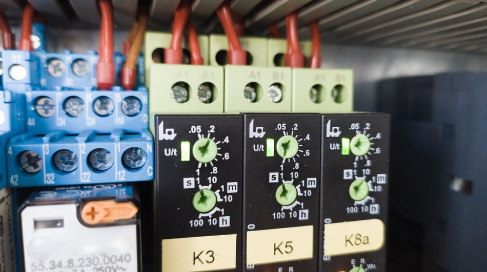
Industrial and PLC Relay Testing
In industrial testing, relays usually direct larger current and voltage values. Here are a few recommendations for industrial PLCs and relays.
Lockout and Tagout (LOTO)
The first step for performing any maintenance on a relay installed in a control panel is to follow a proper lockout and tagout (LOTO) procedure. This involves disconnecting and isolating all power sources and placing warning tags to ensure that the system is not accidentally energized while work is being carried out. Once the panel is safe, the relay can be removed or tested in place.
Verify Voltage Ratings
A critical next step is to verify the coil voltage rating. This is especially important in PLC-controlled systems where relays may operate on either 24 V DC or 120 V AC. If you supply incorrect voltage, it can lead to coil damage or unreliable operation.
Coil Resistance Measurement
The next diagnostic check is to measure the contact resistance using a micro-ohmmeter. High-quality relays typically exhibit an initial contact resistance in the range of 3 to 4 milliohms, indicating good conductive surfaces and minimal losses.
Any significant deviation may suggest contact wear, contamination, or pitting. Insulation resistance testing is also crucial and is performed using a megohmmeter, commonly at 500 V DC. Healthy relays should show insulation resistance values exceeding 100 megohms, ensuring proper isolation between conductive parts.
Dynamic Performance Evaluation
Additionally, you can evaluate dynamic performance by verifying operation and release times with an oscilloscope. These timing characteristics help assess the responsiveness and mechanical integrity of the relay, ensuring it meets system requirements.
Recommended Reading: Preventive Maintenance Checklist For Industrial Machinery
Standards for Relay Testing
Relays used in industrial, commercial, and automotive applications must comply with established international standards to ensure safety, reliability, and interoperability. Here are the common standards for relay testing:
IEC 61810-1
The IEC 61810-1 standard defines the general requirements for electromechanical elementary relays. This standard covers aspects such as performance characteristics, testing conditions, insulation coordination, and expected operational life.
By adhering to IEC guidelines, manufacturers ensure that their relays meet globally accepted benchmarks for quality and safety.
UL 507 and CSA C22.2
In North America, standards such as UL 508 and CSA C22.2 play a significant role in regulating industrial control equipment, including relays. These standards focus on electrical safety, construction requirements, and proper operation under various environmental and load conditions.
UL and CSA certifications are often mandatory for equipment like industrial control panels, ensuring protection against hazards such as short circuits, overloads, and insulation failures.
ISO Mini Relay Specification (ISO 7576)
The ISO Mini Relay specification (ISO 7576) provides detailed guidelines for automotive applications. It dictates the design and functionality of compact relays used in vehicles. It standardizes dimensions, terminal layouts, and performance characteristics, allowing easy replacement and compatibility across different manufacturers.
Collectively, these standards create a unified framework that enhances system reliability, simplifies maintenance, and ensures safe operation across diverse applications.
Conclusion
Properly testing relays involves more than simply swapping parts. Engineers must understand the type of relay, expected coil resistance, contact configuration, load characteristics and environmental conditions. Using a multimeter to measure coil resistance and continuity is often sufficient to diagnose common faults in automotive and household applications. For critical industrial systems, micro-ohm contact resistance measurements, insulation tests and timing analyses provide deeper insight.
Relay technology continues to evolve. Solid-state relays offer long life and fast switching, while advanced electromechanical relays incorporate integrated electronics for diagnostics and protection. Smart relays with built-in microcontrollers can monitor coil currents, contact resistance, and operating temperature, enabling predictive maintenance.
FAQs
1. What is the difference between normally closed and normally open contacts?
Normally open (NO) contacts are open when the relay coil is de-energised and close when the coil is energised. Normally closed (NC) contacts are closed when de-energised and open when energised. Many automotive relays use a changeover configuration with both.
2. Why do I need to measure coil resistance before applying power?
Measuring coil resistance verifies the coil is intact and helps estimate current draw using Ohm's law. Applying voltage to a shorted coil can blow fuses. Typical automotive relays show coil resistance between 50 and 200 ohms.
3. How do I test a relay if I can't remove it from the circuit?
Identify relay pins in the socket using the schematic. Measure coil resistance through harness connectors. Energise the coil and listen for a click. Jumper the common and output terminals to verify the downstream circuit.
4. Can I test a solid-state relay with a multimeter?
A DMM can provide a simple functional test: measure forward voltage of the input LED on diode-test mode (around 1.2 V) and apply rated control voltage to verify output switching. For power SSRs, measure voltage drop under rated load (expect less than 2 V for triac types).
5. Why is contact resistance important?
Contact resistance represents the resistance across closed contacts. High contact resistance causes voltage drops, heat and reduced efficiency. New automotive relays have initial contact resistance below 50 milliohms. Measuring periodically helps detect deterioration before complete failure.
6. What causes relay contacts to weld together?
Contact welding occurs when high currents or inrush currents create arcs that melt contact surfaces. Overloading the relay, switching inductive loads without suppression, or encountering fault currents can weld contacts. Prevention includes sizing relays appropriately and adding snubber circuits.
7. When should I replace a relay instead of cleaning it?
Replace if coil resistance deviates significantly from specification, if there are signs of melted housing, if contact resistance is high or unstable, or if the relay controls safety-critical functions. Sealed relays cannot be opened for cleaning.
8. Do I need a micro-ohmmeter to test all relays?
For routine troubleshooting, a digital multimeter provides adequate testing of coil resistance and continuity. A micro-ohmmeter becomes necessary when verifying high-current contacts or performing predictive maintenance, tracking small increases in contact resistance.
References
O. IC, “A practical approach to relay testing – step‑by‑step guide for accurate results,” Origin‑IC Blog, 2023. [Online]. Available: https://www.origin-ic.com/blog/how-to-test-a-relay-step-by-step-guide-for-accurate-results/47767
“Relay guide,” 12 Volt Planet. [Online]. Available: https://www.12voltplanet.co.uk/relay-guide.html
Panasonic Industrial Devices, “ACTC2R2 – Automotive TC series relay,” Panasonic Industrial Devices Catalog. [Online]. Available: https://na.industrial.panasonic.com/products/relays-contactors/mechanical-power-relays/series/2967/model/3248
Geya, “Solid state relay working – how does a solid state relay work?,” Geya Blog. [Online]. Available: https://www.geya.net/solid-state-relay-working-how-does-a-solid-state-relay-work/
TE Connectivity, “Verification and diagnosis of suspected relay failures,” TE Connectivity Technical Resources. [Online]. Available: https://www.te.com/en/products/relays-and-contactors/electromechanical-relays/intersection/verification-diagnosis-suspected-relay-failures.html?tab=pgp-story
OTS Test Equipment, “How to test an automotive relay,” OTS Test Equipment Blog. [Online]. Available: https://ots-testequipment.net/blog/how-to-test-an-automotive-relay/
Delcon Oy, “What does 30 85 86 87 mean on a relay?,” Delcon Oy Blog. [Online]. Available: https://delcon.fi/what-does-30-85-86-87-mean-on-a-relay/
in this article
1. Introduction2. Fundamentals of Relays3. Tools and Safety Considerations for Relay Testing4. Step-by-Step Relay Testing Procedures5. Failure Modes and Troubleshooting6. Automotive Relay Testing7. Industrial and PLC Relay Testing8. Standards for Relay Testing9. Conclusion10. FAQs11. References