DIN Rail Terminal Blocks: Rails, Selection, and Assembly
DIN rail terminal blocks are modular connectors that secure and organize wires on standardized DIN rails. This article explains rail profiles, ratings, connection methods, wire sizes, accessories, and assembly practices for reliable control panels.

22 Sep, 2026. 29 minutes read
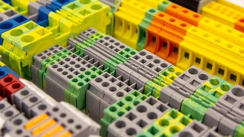
Different types of DIN rail terminal blocks used for electrical connections and control-panel wiring.
Key Takeaways
The DIN rail is a specified mounting component, not a generic bracket. IEC 60715 defines standardized mounting profiles and dimensions. The common TS 35 profile is available in two heights, 35 × 7.5 mm and 35 × 15 mm, alongside other profiles such as TS 15, TS 20/C20, TS 27, and TS 32/G 32.
Terminal block ratings are established under defined installation conditions, not by testing an isolated block. Temperature-rise testing is performed with five terminal blocks mounted in sequence on a compliant rail. The assembly passes when the measured temperature rise remains at or below 45 K.
The same rail-mount terminal block can have different ratings under IEC and UL/CSA requirements. For example, a 3.5 mm-wide push-in terminal block may be rated at 13 A and 300 V under UL/CSA while carrying an IEC rating of 17.5 A and 500 V. The applicable standard and rating system therefore need to be identified before selecting a component.
Double-level terminal blocks increase wiring density with a small change in current rating. A 3.5 mm-wide double-level configuration can provide the same nominal packing density of 285 blocks per meter while carrying 16 A rather than 17.5 A under IEC conditions. The trade-off is higher circuit density within the same DIN-rail footprint.
Accessories determine how maintainable a terminal strip will be in service. Jumpers, end brackets, end covers, partition plates, test plugs, and marking systems support circuit grouping, isolation, identification, testing, and mechanical retention. These accessories are generally standardized within a manufacturer's product system rather than universally interchangeable across manufacturers.
Introduction
A DIN rail terminal block is a modular connection device that terminates one or more conductors and mounts on a standardized rail inside a control panel. Unlike standalone wire connectors, rail-mount terminal blocks are designed as part of an assembly system that can include jumpers, end brackets, end covers, partition plates, markers, and test plugs. Together, these components determine how circuits are connected, grouped, identified, tested, and maintained within the terminal strip.
Selecting DIN rail terminal blocks therefore involves more than matching a conductor to a current rating. The rail profile must be compatible with the terminal block, the block arrangement must accommodate circuit grouping and potential distribution, and the selected connection method must suit the specified wire sizes and installation requirements. Published electrical ratings also need to be interpreted in the context of the applicable standard and test conditions rather than treated as universal values.
The result is a terminal strip whose performance depends on the entire assembly, not simply on the individual blocks. Rail geometry, spacing, conductor preparation, jumper configuration, accessory selection, and thermal conditions can all affect the finished installation. Treating these elements as a coordinated system makes the terminal strip easier to wire, inspect, test, modify, and maintain throughout the service life of the control panel.
Start With the Rail: EN/IEC 60715 Profiles
The mounting rail is the first mechanical interface to specify because its profile determines which components can be mounted and how they are retained. IEC 60715:2017 defines the dimensional and functional requirements for compatible mounting of switchgear, controlgear, and accessories on standardized rail profiles. The current second edition was published in July 2017 and replaced the 1981 edition. Importantly, IEC 60715 addresses the rail primarily as a mechanical mounting system; its 2017 revision explicitly moved the rail's protective-earthing function to the relevant product standards.
Weidmüller identifies DIN rails according to the standardized profiles used in panel construction, including TS 15, TS 20/C20, TS 27, TS 32/G 32, and TS 35. TS 35 is available in two common heights: 35 × 7.5 mm and 35 × 15 mm. The 35 mm dimension identifies the profile width; the second dimension identifies its nominal height.
Standard DIN rail profiles
Designation | Profile | Typical form |
TS 35 | Top-hat rail | 35 × 7.5 mm or 35 × 15 mm |
TS 15 | Top-hat rail | 15 mm profile |
TS 20 / C20 | C-profile | C-section rail |
TS 27 | C-profile | C-section rail |
TS 32 / G 32 | G-profile | G-section rail |
For most contemporary control-panel layouts, TS 35 is the primary profile to evaluate because a broad range of terminal blocks, relays, power supplies, circuit breakers, and other rail-mounted components are designed around it. However, selecting the profile is not enough. The rail height, material, perforation pattern, and compatibility of the intended components must also be checked before the control-panel layout is released.
The distinction between TS 35 × 7.5 and TS 35 × 15 is significant when specifying accessories. Although both profiles share the same nominal 35 mm width, manufacturers can specify different end covers, mounting accessories, or retention components for each height. Weidmüller's product range, for example, lists separate end-cap options for 35 × 7.5 and 35 × 15 rails.
Rail material and finish are part of the electrical specification.
A DIN rail is not necessarily an electrically neutral structural member. Its material, surface treatment, cross-sectional geometry, and intended function can affect electrical performance when the rail is used as part of a protective-earth or bonding arrangement. Weidmüller offers DIN rails in materials including galvanized or passivated steel, aluminum, copper, and plastic, with both perforated and unperforated versions.
A representative example is Phoenix Contact's NS 35/7.5 perforated rail. The rail is 35 mm wide and 7.5 mm high and is manufactured from galvanized, passivated steel. Its product data also specifies an equivalent E-Cu cross-section of 16 mm² and a 1-second short-time withstand current of 1.92 kA under the stated test conditions. These values illustrate why rail material and construction should not be treated solely as mechanical specifications.
Perforated and unperforated rails also serve different installation needs. Perforated rails provide a predefined hole pattern for mounting screws, while unperforated rails allow the installer to position mounting holes according to the panel layout. The choice should therefore account for the mounting plate, required support spacing, available rail length, and installation method rather than being made solely on component availability.
If the DIN rail is intended to perform a protective-earth or PEN function, the selection becomes a separate electrical design decision. The rail material, cross-sectional area, fault-current capability, bonding method, and applicable requirements must all be verified; a rail that mechanically accepts a terminal block is not automatically suitable as a protective conductor.
How the Blocks Attach, and What Holds the Row Together
Rail-mount terminal blocks attach to the DIN rail through an integrated latching mechanism, but the latch alone does not define the finished terminal strip. End brackets, end covers, and partition plates establish the mechanical boundaries and separation of the assembled row. Together, these components control longitudinal movement, exposed conductive surfaces, and separation between functional groups.
End brackets, also called end anchors or end stops, clamp to the DIN rail at the ends of the terminal assembly to prevent the blocks from sliding along the rail. Their mechanical duty is part of the assembly specification rather than a universal characteristic of the rail. Manufacturers may offer standard- and heavy-duty versions for the same rail profile, so the bracket should be selected according to the terminal arrangement and expected mechanical loading.
End covers close the exposed side of the terminal block at the end of a row. Unlike generic mounting hardware, end covers are normally matched to a specific terminal block family and geometry. For example, Rockwell Automation specifies different end barriers for its 1492-P2 single-level and 1492-PD2 double-level terminal blocks. The correct end cover therefore needs to be included in the bill of materials with the corresponding terminal block series rather than selected as a generic DIN-rail accessory.
Partition plates provide additional separation between adjacent terminal blocks or functional groups. They can establish a visible and physical boundary where circuits have different functions or electrical potentials. Phoenix Contact, for example, includes partition plates among its terminal-block system accessories. Their use can also improve identification and reduce the likelihood of accidental contact during inspection or maintenance.
Some devices require an intermediate mounting component rather than a terminal-block mounting foot. Mounting feet can adapt compatible components to a DIN rail, while specialized rail supports can provide alternative mounting orientations for particular installation requirements. These components should be treated as part of the mounting system and verified against both the rail profile and the device being installed.
Recommended reading: Understanding the Connector Landscape: Types and Design Trade-offs
DIN-rail mounting practice that improves maintainability
The physical order of a terminal strip should follow the panel's wiring architecture rather than simply reproducing the numerical order of the schematic. Grouping incoming power, distribution circuits, field I/O, and door-mounted devices into defined terminal sections reduces the distance a technician must trace when inspecting or troubleshooting a circuit. Keeping terminals associated with the same outgoing cable together also makes conductor identification and isolation more straightforward.
Reserve spare positions within functional groups rather than packing every available DIN-rail position. A fully populated and interconnected strip can require the end bracket to be removed and multiple terminal blocks or jumpers to be repositioned before a new circuit can be added. Leaving planned spare positions provides physical capacity for expansion without disturbing existing terminations.
The same principle applies to jumpers. Where adjacent terminals share a potential, use the manufacturer's specified jumper system rather than improvised conductor links. Jumper length, pitch, current rating, and compatibility with the terminal block all need to match the assembly. A partition plate or clearly defined gap can then separate functional groups without compromising the mechanical integrity of the terminal strip.
Ratings Are Measured on the Rail, Not on the Bench
A terminal block's published electrical ratings are established under defined test conditions, not by testing an isolated component on a bench. For rail-mount terminal blocks, those conditions can include the mounting rail, the number of adjacent blocks, conductor cross-section, test current, ambient temperature, and test duration. The DIN rail and surrounding terminal arrangement can therefore form part of the configuration used to establish the component's performance.
Weidmüller's documented qualification procedures illustrate this approach:
Temperature rise: Five terminal blocks are mounted consecutively on a compliant DIN rail and connected in series using harmonized PVC-insulated conductors with the rated cross-section. The assembly is loaded at the specified test current until thermal equilibrium is reached. The measured temperature rise must remain within the applicable 45 K limit.
Voltage drop: Five blocks are mounted on the rail and wired with conductors of the rated cross-section. A defined measuring current is applied, and the voltage drop is measured across the specified current path. For feedthrough terminal blocks, the measured value must remain within the manufacturer's specified limit.
Impulse withstand voltage: Ten terminal blocks are arranged on a compliant rail and subjected to standardized 1.2/50 µs impulse voltages. The test is performed between adjacent conductive parts and between the conductive parts and the mounting rail, with pulses applied at both polarities.
Short-time withstand current: The terminal assembly is subjected to a specified high current for one second. Protective-earth and feedthrough terminal blocks can have different test sequences because their intended current paths and protective functions differ.
Dielectric strength: Five blocks are mounted on a rail and subjected to the specified test voltage for at least 60 seconds between adjacent conductive circuits and between the circuits and the mounting support.
Test | Typical test configuration | What it evaluates |
Temperature rise | Five blocks on a compliant DIN rail | Thermal performance at rated current |
Voltage drop | Five blocks with rated conductors | Resistance of the current path |
Impulse withstand | Ten blocks on a compliant rail | Insulation performance against transient voltage |
Short-time withstand current | Defined terminal assembly | Short-duration fault-current capability |
Dielectric strength | Blocks mounted on a rail | Insulation withstand under test voltage |
Clearance and creepage are also evaluated in the assembled condition. Clearance is the shortest distance through air between two conductive parts. Creepage is the shortest distance along the surface of an insulating material between those parts. Both distances affect insulation performance and depend on the geometry and materials used in the terminal-block assembly.
The practical implication is significant: a datasheet rating represents performance under a defined test configuration. It should not automatically be interpreted as a guaranteed continuous operating condition for a fully populated terminal strip inside a hot, enclosed control cabinet. Increasing terminal density, changing conductor size, raising ambient temperature, or altering the mounting arrangement can change the thermal behavior of the assembly.
What the standards say about derating
The absence of a published derating curve does not mean that thermal effects can be ignored. Weidmüller notes that IEC 60947-7-1, IEC 60947-7-2, and IEC 60947-7-3 do not prescribe a general derating requirement for conventional terminal blocks. Pluggable terminal blocks are treated differently and can fall under IEC 61984, with current-carrying capacity evaluated using the applicable connector test methods.
For pluggable components, IEC 60512-5-2 provides methods for determining current-carrying capacity as temperature increases. Manufacturers can use these methods to publish a derating curve showing the allowable current at different operating temperatures. WAGO, for example, references IEC/EN 60512-5-2 for current-carrying-capacity curves for its connection systems.
For conventional feedthrough terminal blocks, the lack of a standardized derating curve means the designer must evaluate the actual installation rather than apply an assumed correction factor. Cabinet ambient temperature, terminal density, conductor size, heat generated by adjacent components, and enclosure ventilation can all affect operating temperature.
Recommended Reading: Terminal Block Selection: Types, Ratings, and Wiring
A practical design should therefore retain thermal margin rather than treating the nameplate current as a target operating value. A terminal block that passes its type test at its rated current is not necessarily the correct choice for continuous operation at that current in a densely populated, poorly ventilated enclosure.
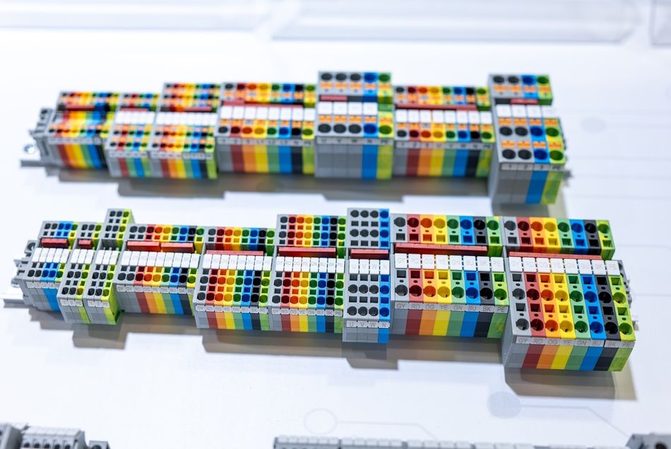
Short-circuit current rating in a UL 508A panel
In North American industrial control panels, terminal blocks can also affect the panel's short-circuit current rating (SCCR). Under UL 508A, terminal blocks without a specified higher SCCR can be assigned the applicable default value under the standard's requirements and tables. The SCCR must therefore be evaluated as part of the complete panel construction rather than treated as an isolated characteristic of the terminal block.
The short-circuit test again uses an assembled configuration. Weidmüller's documented procedure uses terminal blocks mounted on a DIN rail and connected with conductors of the specified cross-section. A short-circuit current is applied at the rated voltage and interrupted by the specified upstream protective device. The terminal assembly must meet the applicable acceptance criteria after the interruption, including remaining suitable for service and maintaining the required electrical performance.
The upstream protective device is therefore part of the SCCR determination. A terminal block's short-circuit capability cannot be separated from the fuse or circuit breaker used to limit and interrupt the fault current. Substituting a different overcurrent protective device can change the conditions under which the documented SCCR applies.
For panel builders, the key distinction is simple: a terminal block's current rating, thermal behavior, dielectric performance, and SCCR are all properties demonstrated under specific test configurations. The correct engineering question is not simply whether a block has the required rating, but whether the documented rating applies to the way the terminal strip will actually be assembled and operated.
Reading Two Numbers for One Block
A rail-mount terminal block can carry different electrical ratings under different certification systems. The physical component does not change, but the applicable test methods, installation assumptions, conductor specifications, and certification requirements can produce different recognized values. Rockwell Automation's 1492-TD017G-EN-P publication illustrates this with the 1492-P2 single-level feedthrough terminal block, which carries separate ratings for UL/CSA, IEC, and ATEX applications.
1492-P2 single-level feedthrough | UL/CSA | IEC | ATEX |
Voltage rating | 300 V AC/DC | 500 V AC/DC | 550 V AC/DC |
Maximum current | 13 A | 17.5 A | 15 A |
Wire range / rated cross-section | 26–14 AWG | 1.5 mm² | 1.5 mm² |
The differences are not interchangeable. A designer should select the rating column that corresponds to the certification and installation requirements governing the application. For example, the 17.5 A IEC rating cannot simply be substituted for the 13 A UL/CSA rating when designing a North American panel. The applicable certification basis, conductor requirements, and installation standard determine which published value can be used.
The physical dimensions remain the same across these rating schemes. The 1492-P2 measures 3.5 × 33.5 × 55 mm, requires an 8 mm strip length, and can be installed at a nominal density of 285 terminal blocks per meter of rail. Its housing is specified for a temperature range of −60 to +130°C. These mechanical and environmental specifications are separate from the electrical ratings and should be evaluated independently during selection.
This distinction becomes important when comparing terminal blocks from different manufacturers. Two blocks with the same nominal width and similar connection technology may have different UL/CSA, IEC, or other regional ratings. The correct comparison therefore requires more than matching voltage and current; the designer should verify the applicable standard, conductor size, connection method, temperature conditions, spacing, and certification markings.
For panel builders, the practical rule is straightforward: use the rating recognized for the governing installation standard, not simply the highest number printed in the datasheet. The highest published current or voltage value may belong to a different certification regime and may not be valid for the intended application.
Single-Level and Double-Level: Buying Panel Density
Single-level terminal blocks provide one connection level per block, while double-level blocks place two electrically isolated connection levels within the same rail width. This increases the number of conductors that can be terminated within a given section of DIN rail without increasing the block width. The trade-off is that multi-level construction can increase the block's height and depth and may reduce some electrical ratings compared with an equivalent single-level model.
Rockwell Automation's 1492-P2 single-level and 1492-PD2 double-level feedthrough blocks illustrate the trade-off. Both are 3.5 mm wide and have a nominal density of 285 blocks per meter, but their overall dimensions and certification-specific ratings differ.
Parameter | 1492-P2 single-level | 1492-PD2 double-level |
Dimensions (W × H × L) | 3.5 × 33.5 × 55 mm | 3.5 × 45 × 84 mm |
Density | 285 pcs/m | 285 pcs/m |
UL/CSA | 300 V, 13 A | 300 V, 13 A |
IEC | 500 V, 17.5 A | 500 V, 16 A |
ATEX | 550 V, 15 A | 440 V, 13.5 A |
The important point is that rail width does not tell the whole density story. The double-level block provides two connection levels without increasing the 3.5 mm width, but its height increases from 33.5 mm to 45 mm and its length increases from 55 mm to 84 mm. That additional envelope can affect wire-duct clearance, bending space, marker visibility, screwdriver access, and access to the upper and lower connection levels.
The electrical comparison also matters. The UL/CSA rating remains 300 V and 13 A for both models, while the IEC rating decreases from 17.5 A for the single-level block to 16 A for the double-level block. Under ATEX, the difference is larger: 550 V and 15 A for the single-level model versus 440 V and 13.5 A for the double-level model. Therefore, choosing a double-level block should not be based solely on the number of circuits gained per unit of DIN rail; the applicable certification, operating current, voltage, and available enclosure space must also be checked.
For dense control panels, the practical calculation is circuits per rail length, not simply blocks per meter. A double-level arrangement can increase the number of available connection points without increasing rail width, but only where its dimensions, wiring access, and applicable ratings suit the installation. This makes double-level blocks useful for compact I/O and control wiring, while single-level blocks may provide simpler access and greater electrical margin for higher-current circuits.
Design check: before replacing a single-level block with a double-level version, verify four things together: available rail width, vertical and depth clearance, required electrical rating under the governing certification system, and accessibility for wiring and maintenance.
Potential Distribution: Jumpers, Bridges, and Commoning
Jumpers and bridges distribute a common electrical potential across a group of terminal blocks. Instead of creating individual loop wires between adjacent terminals, a jumper provides a purpose-designed connection that can be installed, removed, or configured as part of the terminal block system. This reduces wiring work and can make the finished terminal strip easier to inspect and modify.
Phoenix Contact's FBS plug-in bridges, for example, are designed for potential distribution between terminal blocks with the same nominal cross-section. The bridge family is available with multiple contact tabs, allowing several adjacent terminals to be connected with one component. The rated current depends on the bridge design and terminal-block pitch; for example, Phoenix Contact specifies 24 A for 5.2 mm pitch bridges and 32 A for 6.2 mm pitch bridges.
Some bridge systems can be shortened with a cutting tool, while individual contact tabs can be removed to create a bridge that skips selected terminals. This allows commoning to follow the actual circuit arrangement rather than requiring every terminal in a row to share the same potential. The manufacturer's instructions should be followed when modifying a bridge because removing contact tabs changes the resulting connection pattern and may affect its permissible application.
Several bridge types serve different wiring arrangements:
Bridge type | Primary function | Typical application |
Standard bridge | Connects terminals with the same nominal cross-section | Common potential across adjacent terminals |
Reducing bridge | Connects terminals with different nominal cross-sections | Distributing a larger incoming conductor to smaller conductors |
Potential bridge | Connects different levels within a multi-level terminal block | Bridging upper and lower levels |
Short-circuit plug | Provides a removable connection between potentials | Temporary shorting, testing, or commissioning |
A reducing bridge is useful when a larger feed-in terminal supplies several smaller distribution terminals. A potential bridge performs the same basic commoning function between levels of a double-level or multi-level block. Short-circuit plugs serve a different purpose: they provide a removable electrical connection and are not intended to function as permanent retained bridges.
WAGO uses a similar system approach for rail-mount terminal blocks, with bridge options that include continuous, adjacent, step-down, and vertical configurations, along with modular tap-off solutions. The terminology varies between manufacturers, but the underlying design principle is the same: the bridge must match the terminal-block family, connection geometry, and intended electrical function.
Do not treat jumpers as universal accessories. Bridge pitch, contact geometry, terminal-block family, current rating, and the number and arrangement of contact tabs all determine compatibility. A 5.2 mm bridge, for example, is not interchangeable with a 6.2 mm system simply because both blocks perform the same basic function. Mixing manufacturers within a terminal strip can therefore create compatibility problems even when the individual terminal blocks appear mechanically similar.
For this reason, specify the jumper and terminal block as a system. Confirm the manufacturer's compatible bridge series, pitch, nominal cross-section, current rating, and required connection pattern before assembly.
Testing and Marking: Making the Strip Serviceable
A terminal strip is not only a connection point; it is also an interface for testing, isolation, and maintenance. Accessories such as test plugs, disconnect plugs, fuse plugs, and markers allow technicians to inspect or modify a circuit without unnecessarily disturbing the conductors. Designing these functions into the terminal strip makes troubleshooting more controlled and reduces the need to dismantle completed wiring.
Test plugs provide access to the circuit through a dedicated test connection or function slot. Phoenix Contact's MPS test plugs are available with 2.3 mm and 4 mm test probes. The 2.3 mm version can also be used with the test connections of spring-cage terminal blocks, allowing the terminal's function slot to remain available for potential distribution. Alignable test plugs can be assembled into test probe blocks, while spacer plates can be used to skip selected terminal positions in a row.
Repeated testing also places mechanical demands on the test connection. Phoenix Contact offers service plugs with silver-plated contact surfaces for repeated insertion and removal. WAGO rail-mount terminal blocks similarly provide dedicated test connections that accept 2 mm test plugs. The practical advantage is that a technician can connect a meter or test instrument without loosening the primary conductor termination.
Disconnect functionality can also be incorporated into the terminal block rather than provided by a separate disconnect device. For terminal blocks with a standardized disconnect zone, available function plugs can include isolating plugs, feed-through connectors, feed-through barriers, fuse plugs, and component connectors. An isolating plug allows a circuit to be opened manually for testing or maintenance while retaining the plug within the terminal system when the circuit is open.
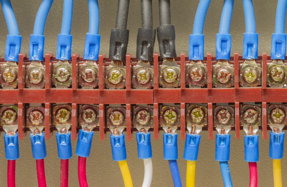
Fuse plugs extend the same concept by adding overcurrent protection to a terminal block configured to accept the appropriate fuse accessory. Versions can include an LED indicator to provide a visual indication of the fuse condition or circuit status, depending on the specific product design. Pick-off plugs provide another option by creating an additional load connection through the function slot; their electrical rating must be checked against the manufacturer's specified conditions and any applicable derating.
Marking completes the serviceability system. Terminal markers, marker carriers, and warning labels provide a consistent identification scheme so that conductors, circuits, and terminal positions can be traced during wiring, commissioning, troubleshooting, and maintenance. A clear marking system is most useful when it is applied consistently across the entire terminal strip rather than only to terminals that appear difficult to identify.
Mark every terminal, and establish the identification scheme before wiring begins. The terminal designation should correspond with the electrical drawings and conductor or circuit identification used elsewhere in the control cabinet. Consistent marking reduces the time required to trace a circuit and lowers the chance of reconnecting a conductor incorrectly after testing or maintenance.
The result is a terminal strip that can be connected, tested, isolated, protected, and identified without dismantling the wiring. Those functions should be considered during terminal-block selection rather than added after the control panel has already been assembled.
Recommended reading: 6 Connectivity Solutions for Industrial Robotic Applications
Grounding: The Rail as a Protective Conductor Path
Protective conductor terminal blocks differ from feed-through terminal blocks in how the protective circuit is established. Instead of relying solely on an insulated internal current path between two conductor terminals, a PE terminal block makes an electrical connection between the protective conductor and its mounting support, typically the DIN rail. IEC 60947-7-2 covers protective conductor terminal blocks for copper conductors and specifies requirements for the electrical and mechanical connection between the conductors and the fixing support.
The testing requirements reflect this construction. For a PE terminal block, voltage drop is evaluated through the protective connection and mounting support rather than only across the internal conductor path. The applicable test requirements also include short-time withstand current testing intended to verify the protective connection under fault conditions. These tests are distinct from those applied to conventional feed-through terminal blocks because the protective path includes the connection to the mounting support.
This does not mean that every DIN rail automatically becomes a protective conductor. Whether the rail can serve as part of a PE or PEN system depends on its material, cross-sectional characteristics, mechanical continuity, electrical connections, and the requirements of the applicable installation standard. Weidmüller, for example, identifies conditions under which DIN rails and C-profile rails can be used as PE or PEN conductors and specifies additional requirements for PEN applications, including permissible rail materials and consideration of short-circuit and thermal currents.
PEN applications require additional care because a PEN conductor combines protective and neutral functions. The conductor system must satisfy the applicable requirements for both functions, including minimum cross-sectional and continuity requirements. A rail that is suitable as a mechanical mounting support therefore cannot be assumed to be suitable as a PEN conductor simply because it is metallic.
The enclosure connection also needs to be designed deliberately. A galvanized steel DIN rail carrying a row of PE terminal blocks may form part of the protective bonding arrangement, but the electrical connection between the rail and the enclosure or protective bonding system should be established through a specified bonding method. Mounting screws, painted surfaces, corrosion, mechanical joints, or incidental metal-to-metal contact should not be treated as an assumed protective connection unless the equipment design and applicable standard specifically permit it.
Design check: when using PE terminal blocks, verify the terminal block's protective-conductor rating, rail compatibility, rail continuity, rail-to-enclosure bonding method, and applicable fault-current requirements as one system. The fact that a terminal block clips onto a conductive DIN rail establishes mechanical attachment; it does not, by itself, establish that the complete rail assembly is an approved protective conductor path.
Conductor Preparation: Wire Sizes, Ferrules, and Crimping
Wire size is one of the first compatibility checks when selecting a rail-mount terminal block. A block may have sufficient current capacity for a circuit but still be unsuitable if its clamping unit does not accept the conductor size or conductor type. Check both ends of the specified range because a terminal block has a minimum as well as a maximum conductor size. For example, the Rockwell 1492-P2 accepts 26 to 14 AWG under its UL/CSA specification and specifies an 8 mm strip length, while WAGO rail-mount terminal blocks extend from small control conductors to high-current conductors as large as 185 mm² (350 kcmil), depending on the product family.
Published conductor ranges may also differ between certification systems. AWG and mm² are different sizing systems and should not be treated as directly interchangeable labels. The 1492-P2, for example, lists 26 to 14 AWG under UL/CSA while specifying a rated cross-section of 1.5 mm² under IEC and ATEX. The applicable conductor range should therefore be taken from the certification and installation requirements governing the panel rather than converted from one column to another by assumption.
The conductor type matters as well. Terminal blocks can specify separate permissible ranges for solid, stranded, fine-stranded, or ferruled conductors. Connection technology also affects preparation requirements: a push-in or spring-clamp terminal may accept several conductor types, but each type still has to fall within the manufacturer's specified range and preparation requirements.
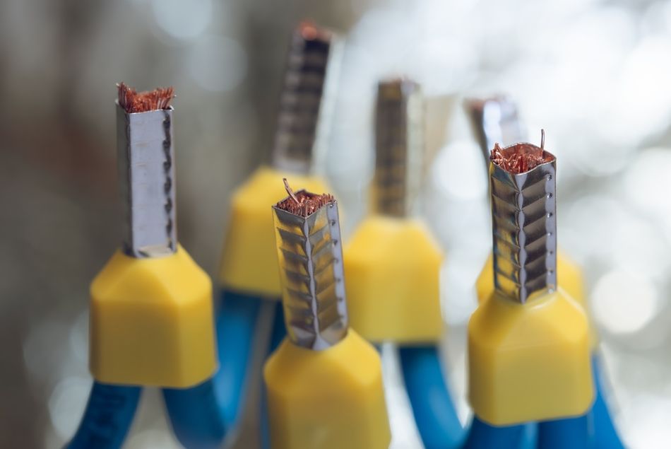
Ferrules are commonly used when terminating fine-stranded conductors. A ferrule creates a consolidated termination at the end of a stranded conductor, but it does not make an incompatible conductor acceptable. The ferrule must match the conductor cross-section, its length must suit the terminal's clamping area, and the crimping tool must be appropriate for the ferrule.
Crimp quality is part of the electrical connection. Manufacturer documentation can specify the compatible ferrule, required strip length, and acceptable crimp profile for a particular terminal-block family. Rockwell's specifications, for example, identify compatible ferrules by conductor size and specify hand crimp tools and crimp profiles for those ferrules. A properly selected ferrule with an incorrect crimp is therefore not equivalent to a properly prepared termination.
Ferrule color can provide a useful visual check, but it should not be treated as a universal wire-size code. Color systems vary between standards, manufacturers, and markets, and some sizes may share a color under a particular system. The conductor size, ferrule specification, and manufacturer's documentation remain the authoritative checks when verifying a termination.
Ring terminals belong to a different connection method. They are designed to terminate a conductor onto a stud, screw, or other threaded connection rather than into the clamping unit of a conventional rail-mount terminal block. Barrier-style terminal strips and stud-type connections commonly use ring terminals, while push-in and spring-clamp rail-mount terminal blocks generally accept the conductor or ferrule directly. If a design requires ring terminals at the rail interface, verify that the selected terminal block is specifically designed for that connection method rather than assuming a standard DIN rail terminal can accommodate them.
Conductor-preparation check: verify the conductor material and type, AWG or mm² range, strip length, ferrule requirements, ferrule dimensions, and crimp specification against the terminal block's documentation. The correct current rating is only one part of a valid termination; the conductor and its preparation must also match the connection system.
Vibration, Shock, and Environment
A control panel installed on a machine skid, vehicle, or other moving equipment can experience vibration and shock that a stationary laboratory installation does not. Terminal-block manufacturers therefore evaluate mechanical robustness using environmental test methods in addition to the electrical tests required for terminal blocks. WAGO, for example, describes vibration testing according to IEC/EN 60068-2-6, where controlled frequency, acceleration, and amplitude are applied across multiple axes to evaluate whether prolonged vibration affects the electrical connection.
Recommended Reading: High Performance Connectivity in Robotics
Shock testing addresses a different loading condition. IEC/EN 60068-2-27 applies discrete mechanical shocks rather than continuous vibration, with the severity defined by parameters such as acceleration and pulse duration. The applicable test level depends on the product and intended application, so a manufacturer's stated shock qualification should be read as a property of the tested product and configuration rather than as a universal rating for all terminal blocks.
The conductor connection is evaluated separately. Pull-out testing under EN 60947-7-1 and EN 60998-2-2 assesses whether the clamping system can retain the specified conductor when a defined tensile force is applied. A separate bending-stress test evaluates whether moving a connected conductor causes an unacceptable change in the electrical contact. These tests are important because a terminal can remain mechanically attached to the DIN rail while the conductor connection itself is compromised.
Environmental selection also extends beyond mechanical loading. Temperature, humidity, contamination, corrosion, and exposure to chemicals can affect the housing, insulating materials, metal contacts, and connection system. A published housing temperature range, therefore, should not automatically be interpreted as the permissible ambient temperature for the complete terminal assembly. The applicable datasheet should be checked for the specific operating, storage, and electrical-rating conditions associated with the stated temperature range.
Recommended Reading: Rugged Connectors Meet the Connectivity Demands of Transportation
For example, Rockwell specifies a housing temperature range of −60 to +130°C for the 1492-P2. That specification describes the permitted temperature range for the housing material under the manufacturer's stated conditions; it does not by itself establish that the terminal can continuously carry its full rated current at +130°C.
Environmental check: match the terminal block to the actual installation environment, not simply its electrical rating. For equipment exposed to vibration or shock, verify the manufacturer's mechanical test data, conductor-retention performance, mounting arrangement, and applicable environmental limits. For elevated or low temperatures, check how temperature affects both the material rating and the electrical rating before treating the published housing range as an operating limit.
The Rest of the Rail: What Shares the Strip
A terminal block row rarely has the DIN rail to itself. DIN rail circuit breakers, power supplies, relays, interface modules, and other control components can share the same 35 mm rail. Weidmüller identifies terminal blocks, relays, and power supplies among the equipment designed for DIN rail mounting. The resulting layout is therefore an assembly of components with different thermal, wiring, clearance, and service requirements rather than a row of terminal blocks considered in isolation.
Two layout practices are useful. First, allow the clearance specified by the power-supply manufacturer rather than packing terminal blocks tightly against a DIN rail power supply. A power supply can contribute significant heat inside an enclosed control cabinet, and restricted airflow or inadequate spacing can affect its thermal performance. The required clearance should come from the specific power-supply documentation rather than from a generic spacing rule.
Second, control the number of connection technologies used within a serviceable section of the terminal strip. Screw clamp and push-in terminal blocks can coexist when the design requires it, but they impose different installation procedures, including conductor preparation and, for screw connections, specified tightening requirements. A consistent connection method can simplify installation, inspection, troubleshooting, and maintenance because technicians encounter fewer termination procedures within the same work area.
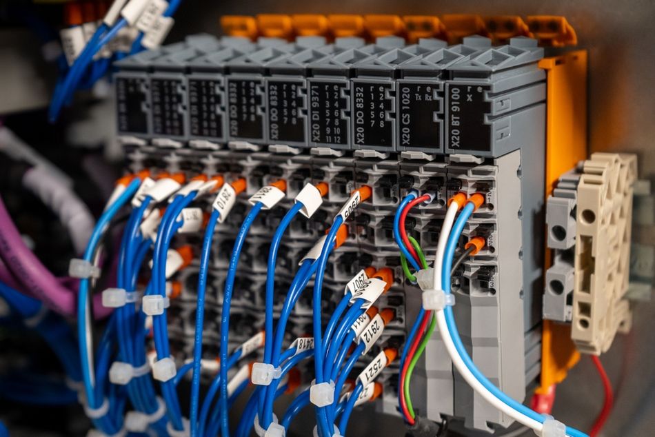
The panel door creates another wiring group that should be planned from the beginning. Push-buttons, selector switches, pilot lights, and other door-mounted devices are connected to the stationary control panel through flexible door wiring. Reserving a contiguous group of terminals for these circuits keeps the door harness organized and makes it easier to disconnect, troubleshoot, or replace the door assembly.
The door-terminal group should follow the physical arrangement of the door devices where practical. For example, terminals serving push-buttons, selector switches, and pilot lights can be grouped and identified according to the corresponding device and electrical drawing. This reduces conductor crossover and makes the relationship between the door wiring and the terminal strip easier to trace.
A useful rule is to organize the rail according to function and service path, not simply available space. Group power distribution, control circuits, field I/O, safety-related circuits, and door wiring according to the panel's electrical architecture, while maintaining the required electrical separation and manufacturer-specified clearances. A few minutes spent establishing these groups before assembly can make the finished control cabinet substantially easier to wire, inspect, and service.
Recommended reading: Selecting Industrial Power Supplies for Automation
Common Mistakes
The most common terminal-strip errors are usually not caused by choosing the wrong terminal block in isolation. They occur when the rail, accessories, electrical ratings, conductor preparation, and layout are specified separately rather than as one assembly.
Choosing the rail last. The DIN rail profile and height affect accessory compatibility. For example, components intended for a 35 × 15 mm rail may not be interchangeable with accessories designed for a 35 × 7.5 mm profile. Specify the rail and compatible accessories as a system before purchasing components.
Reading the wrong ratings column. A single terminal block can have different UL/CSA, IEC, and other certification-specific ratings. Do not select the highest value simply because it appears on the datasheet; use the rating applicable to the certification and installation requirements governing the panel.
Omitting end brackets. Terminal blocks can move along the rail if the assembled row is not mechanically restrained. Select end brackets appropriate to the terminal-block family, rail profile, and expected assembly, and install them at the boundaries of the terminal strip as specified by the manufacturer.
Leaving out the end cover or required separation accessory. End covers, partition plates, and barriers are part of the terminal-block system rather than optional cosmetic components. They can provide electrical separation, protect exposed surfaces, and complete the physical arrangement of the terminal strip. Verify the required accessories against the exact block family before assembly.
Treating the nameplate current as independent of the installation. Published electrical ratings are established under defined test configurations involving factors such as conductor size, terminal arrangement, mounting rail, temperature, and test duration. The applicable rating therefore needs to be checked against the actual terminal-strip arrangement and operating environment rather than assumed to transfer unchanged to every installation.
Mixing manufacturers within a jumpered group. Jumpers and bridges are typically specific to a terminal-block family, pitch, geometry, and connection system. Two blocks with the same width or similar appearance may not accept the same bridge. Keep a common group within a compatible accessory system unless the manufacturer explicitly confirms interoperability.
Marking after wiring. Identification is easier to apply and verify when the terminal arrangement is established but before the wiring becomes congested. Mark terminal positions consistently with the electrical drawings and conductor identification so that the completed strip can be traced without relying on memory or wire color.
Checking only the maximum wire size. A terminal block also has a minimum permissible conductor size, and the permitted range can differ by certification system or conductor type. Verify the complete wire-size range, conductor type, strip length, and ferrule requirements before terminating the first conductor.
Ignoring physical clearance. A terminal block can fit on the DIN rail and still interfere with wire duct, cabinet doors, adjacent devices, or conductor bend radius. Check the complete height and depth envelope of the assembled terminal strip, including wires and accessories, rather than using the block width alone.
Adding jumpers after the strip is populated. Commoning should be part of the circuit layout from the beginning. Adding bridges later can require repositioning terminal blocks, removing end restraints, or disturbing existing wiring. Define the common potentials, bridge positions, and spare terminals before the strip is assembled.
The underlying mistake is treating the terminal block as an isolated component. A reliable terminal strip is a coordinated assembly of rail, blocks, conductors, jumpers, accessories, identification, spacing, and enclosure conditions. Selecting each item against the others prevents many of the problems that otherwise appear during wiring, commissioning, or maintenance.
Conclusion
A DIN rail terminal block is a standardized component, but the terminal strip is a designed assembly. Start with the rail profile and compatible accessories because the rail establishes the mechanical foundation for the blocks, and where the rail is used as part of a protective conductor system, its electrical suitability must also be verified. From there, select terminal blocks according to the applicable certification, conductor range, connection method, current and voltage requirements, and the actual conditions in which the assembled strip will operate.
Published ratings should be read as values established under defined test conditions rather than as isolated numbers that apply to every installation. The mounting rail, conductor size, terminal arrangement, temperature, connection technology, and certification basis can all affect how a rating applies to the finished assembly. The same discipline should carry through to the accessory layer, where jumpers, end brackets, end covers, partition plates, test plugs, disconnect accessories, and marking determine how easily the strip can be wired, tested, maintained, and modified.
The best terminal-strip design, therefore, is not simply the one that fits the most terminals onto a DIN rail. It is the one that provides the required electrical capacity while preserving mechanical security, conductor compatibility, thermal margin, accessibility, identification, and serviceability. Treating the rail, terminal blocks, conductors, and accessories as one engineered system produces a control-panel connection point that remains understandable and maintainable long after the initial wiring is complete.
Frequently Asked Questions
What is a DIN rail terminal block?
A DIN rail terminal block is a modular connection device that mounts on a standardized DIN rail inside a control panel and terminates electrical conductors through a screw, spring, push-in, or other clamping system. IEC 60947-7-1 covers terminal blocks for copper conductors across specified conductor sizes and for circuits within its stated voltage limits. Check the applicable product standard and manufacturer's specifications for the specific terminal-block type.
How do I attach a terminal block to a DIN rail?
Most rail-mount terminal blocks attach by engaging an integrated mounting mechanism with the DIN rail profile and snapping or locking into position. Then mechanically restrain the completed row with compatible end brackets or end stops. Some components use a mounting foot or adapter when their mounting arrangement does not directly match the rail profile. Always follow the manufacturer's mounting sequence because the locking mechanism and required accessories vary between product families.
Which DIN rail size do I need?
For many control-panel applications, 35 mm DIN rail is the common starting point, particularly the TS 35 profile. TS 35 is available in 35 × 7.5 mm and 35 × 15 mm forms, while other standardized profiles include TS 15, TS 20/C20, TS 27, and TS 32/G 32. The correct choice is determined by the terminal-block and accessory system being used; components designed for one rail profile or height should not be assumed to fit another.
How do I choose the right DIN rail terminal block?
Start with the conductor requirements: wire size, conductor type, preparation method, and required connection technology. Then check the certification or installation scheme governing the panel and use the corresponding voltage and current ratings. Select the required function—such as feed-through, protective conductor, fuse, disconnect, or multi-level—before determining the required terminal density and accessory system. Finally, verify compatible jumpers, end brackets, end covers, test accessories, markers, and available enclosure space.
Can I use the DIN rail as a ground busbar?
A PE terminal block can establish an electrical connection between the protective conductor and its mounting support, but that does not mean every DIN rail automatically qualifies as a protective conductor. Using a rail as part of a PE or PEN system depends on the rail material, dimensions, electrical continuity, bonding arrangement, fault-current requirements, and applicable installation standard. Where a rail is intended to perform a protective-conductor function, its suitability and the rail-to-enclosure connection must be specifically verified.
Do terminal blocks need to be derated when packed together?
There is no single derating rule that can be applied to every terminal block. Conventional non-pluggable terminal blocks are evaluated under defined test configurations, including specified numbers of adjacent blocks, conductor sizes, currents, and temperature-rise limits. The manufacturer's published rating and test conditions therefore need to be compared with the actual installation rather than applying a generic packing factor. Pluggable terminal systems may fall under different standards and current-carrying-capacity methods, so their derating requirements should be checked separately.
What is the difference between single-level and double-level terminal blocks?
A double-level terminal block provides two electrically isolated connection levels within the same rail width, increasing connection density without increasing the block's width. In Rockwell's push-in range, the 1492-P2 single-level and 1492-PD2 double-level models are both 3.5 mm wide and have a nominal density of 285 pieces per meter. However, the IEC maximum current is 17.5 A for the single-level model and 16 A for the double-level model, while the overall dimensions increase from 33.5 × 55 mm to 45 × 84 mm. The choice therefore involves both panel density and the available electrical and physical margins.
Are fuse terminal blocks covered by their own standard?
Yes, IEC 60947-7-3 specifies requirements for fuse terminal blocks intended for cartridge fuse-links within its stated application limits. Other specialized terminal-block functions can also have their own product standards; for example, IEC 60947-7-4 addresses PCB terminal blocks. The relevant standard should therefore be identified from the terminal block's function rather than assuming that every terminal block is covered by the same requirements.
References
[1] International Electrotechnical Commission, IEC 60715:2017, Dimensions of Low-Voltage Switchgear and Controlgear—Standardized Mounting on Rails for Mechanical Support of Switchgear, Controlgear and Accessories, 2nd ed. Geneva, Switzerland: IEC, 2017.
[2] International Electrotechnical Commission, IEC 60947-7-1:2025, Low-Voltage Switchgear and Controlgear—Part 7-1: Ancillary Equipment—Terminal Blocks for Copper Conductors, 4th ed. Geneva, Switzerland: IEC, 2025.
[3] International Electrotechnical Commission, IEC 60947-7-2:2009, Low-Voltage Switchgear and Controlgear—Part 7-2: Ancillary Equipment—Protective Conductor Terminal Blocks for Copper Conductors, 3rd ed. Geneva, Switzerland: IEC, 2009.
[4] M. P. Filippakou, C. G. Karagiannopoulos, P. D. Agoris, and P. D. Bourkas, “Electrical contact overheating under short-circuit currents,” Electric Power Systems Research, vol. 57, no. 2, pp. 141–147, 2001, doi: 10.1016/S0378-7796(01)00081-5.
[5] L. Xu, S. Ling, D. Li, and G. Zhai, “Vibration-induced dynamic characteristics modeling of electrical contact resistance for connectors,” Microelectronics Reliability, vol. 113, Art. no. 113868, 2020, doi: 10.1016/j.microrel.2020.113868.
[6] S. Ling, L. Xu, D. Li, and G. Zhai, “Fretting wear reliability assessment methodology of gold-plated electrical connectors considering manufacture parameters distribution,” Microelectronics Reliability, vol. 114, Art. no. 113787, 2020, doi: 10.1016/j.microrel.2020.113787.
[7] Z. Li, C. Li, C. Zhao, and H. Lu, “Reliability-based design optimization of electrical connectors,” Reliability Engineering & System Safety, vol. 272, Art. no. 112660, 2026, doi: 10.1016/j.ress.2026.112660.
in this article
1. Key Takeaways2. Introduction3. Start With the Rail: EN/IEC 60715 Profiles4. How the Blocks Attach, and What Holds the Row Together5. Ratings Are Measured on the Rail, Not on the Bench6. Reading Two Numbers for One Block7. Single-Level and Double-Level: Buying Panel Density8. Potential Distribution: Jumpers, Bridges, and Commoning9. Testing and Marking: Making the Strip Serviceable10. Grounding: The Rail as a Protective Conductor Path11. Conductor Preparation: Wire Sizes, Ferrules, and Crimping12. Vibration, Shock, and Environment13. The Rest of the Rail: What Shares the Strip14. Common Mistakes15. Conclusion16. Frequently Asked Questions17. References