Capacitors in Parallel: Theory, Design, and Practical Implementation
Capacitors in parallel are ubiquitous in digital and analog hardware. When used properly, they increase capacitance, reduce unwanted impedance and noise, and improve power integrity across a broad frequency range.

21 Aug, 2025. 14 minutes read
Key Takeaways
Capacitance adds in parallel, increasing total capacitance, since voltage is shared.
Parallel capacitors reduce ESR and ESL, lowering impedance for high-speed circuits.
Using bulk plus small ceramic capacitors covers broad frequencies and boosts decoupling.
Short leads, close placement, and proper planes minimize parasitics and anti-resonance.
Optimized can cut power noise by 66.7%, improve rise times by 20%, and reduce jitter by 37.5%.
Introduction
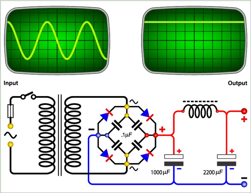
Supplying clean, stable power is crucial for reliable electronic systems, from high-speed FPGA boards to embedded processors. Capacitors placed across supply rails act as local energy reservoirs, filtering noise and stabilizing voltage during current spikes. Connecting multiple capacitors in parallel increases the total capacitance and lowers impedance, essential for effective decoupling and bypassing. Designers use parallel networks of ceramic, electrolytic, and film capacitors to suppress power supply noise across a wide frequency range.
This article discusses the theoretical foundations of capacitors in parallel, discusses why engineers combine capacitors, and provides detailed guidelines for selecting and arranging them in real circuits. We will look at how equivalent capacitance is calculated, how energy is stored and delivered, and how parasitic effects influence performance. Practical examples show how to implement parallel networks for decoupling microcontrollers, FPGAs, and power converters. Along the way, we will reference industry data and standards to ground the discussion in current practice.
Fundamentals of Capacitance
Definition and Basic Formulae
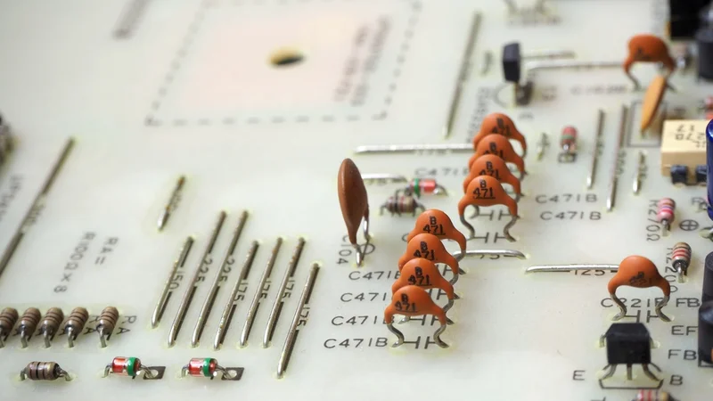
A capacitor is an electrical component that stores energy in an electric field. It consists of two conductive plates separated by an insulator (dielectric). The capacitance C of a capacitor is a measure of how much charge it can store per unit voltage:

where Q is the charge and V is the voltage across the plates. The energy stored in a capacitor is given by several equivalent expressions:
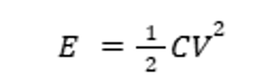 | Energy stored as a function of Capacitance and Voltage |
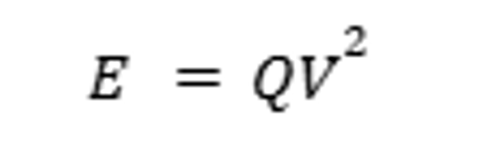 | Energy, as a function of Charge and Voltage |
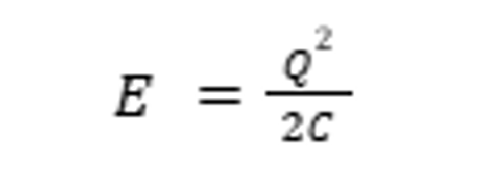 | Energy as a function of Charge and Capacitance |
These formulas show that increasing capacitance or voltage increases the stored energy. Capacitors are widely used to filter, smooth, and temporarily store charge in analog and digital systems.
Capacitors in DC and AC Circuits
The analogy of an ideal capacitor suggests that a capacitor will behave as an open circuit for DC voltages. That’s because once it is fully charged, there will be no net current flow. On the other hand, AC circuits use the capacitor’s reactance:

Hence, at higher frequencies, the impedance drops, and the capacitor therefore acts as a short circuit for AC signals.
In digital circuits, due to high switching frequencies, capacitors can effectively contain high-frequency elements, making them critical for noise suppression and decoupling.
Suggested Reading: Types of Circuits: A Comprehensive Guide for Engineering Professionals
Capacitance of Ideal Series and Parallel Networks
Capacitors can be combined in series or parallel. For series equivalent capacitance, the reciprocals add:

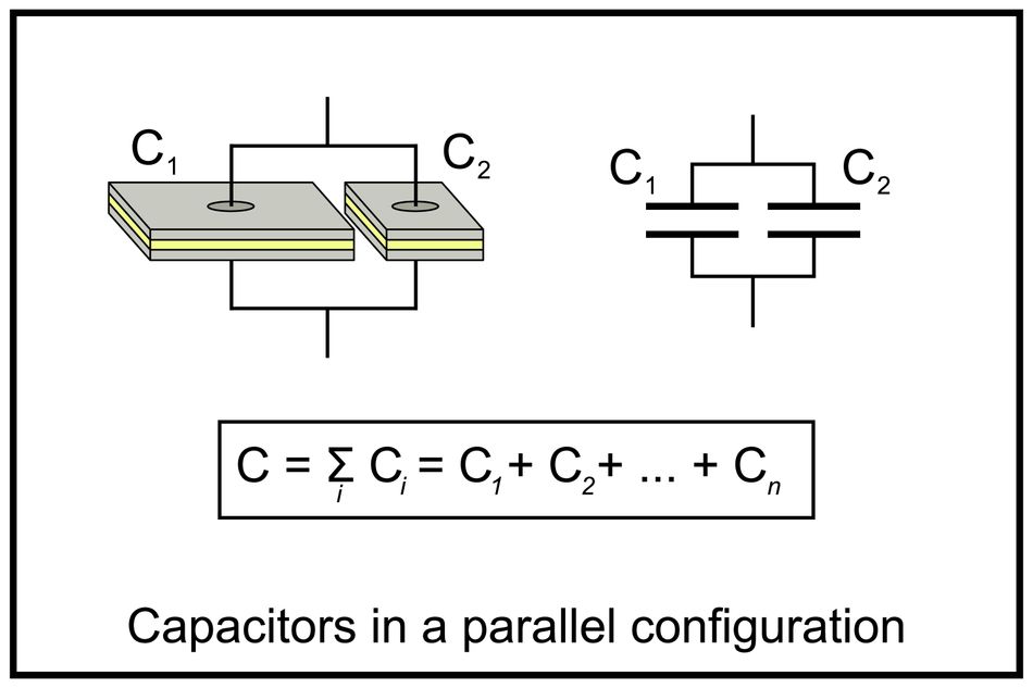
In a parallel combination, the capacitances add directly. If you connect n capacitors so that all positive plates join together and all negative plates join together, the equivalent capacitance is:

This result arises because putting capacitors in parallel effectively increases the plate area of the composite structure; more area results in higher capacitance.
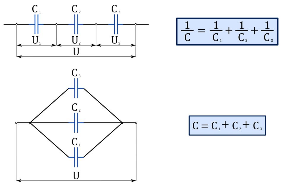
The equivalent capacitance in a series combination is always less than the lowest capacitance in the circuit, while the parallel equivalent capacitance is always higher than the highest capacitance in the circuit.
Recommended Reading: Capacitor Polarity: Ensuring Proper Orientation for Optimal Performance
Voltage and Charge Distribution in Parallel Networks
One key property of a parallel network is that each capacitor experiences the same voltage drop. When a voltage source is applied across a parallel combination, the potential difference is identical across all capacitors because the positive nodes are connected and the negative nodes are connected. The charge stored on each capacitor is proportional to its capacitance:

Consequently, larger capacitors will store proportionally more charge, but they will all see the same voltage. In contrast, current divides according to the impedance of each branch; lower‑impedance capacitors will draw more current during transients.
Why Connect Capacitors in Parallel?
When capacitors are connected in parallel, the voltage drop across each remains the same, while the stored charge is the sum of individual charges across each capacitor. It presents several advantages, such as:
Increasing Total Capacitance
The formula for parallel capacitance suggests that the total capacitance is the sum of individual capacitances. So, we can connect capacitors in parallel to achieve a specific capacitance value that is not available as a single component.
For example, if you need a total of 12 µF and only have standard values of 10 µF and 2 µF, you can place them in parallel to reach the desired total. Similarly, decoupling networks often require tens or hundreds of microfarads distributed around a printed circuit board.
Suggested Reading: Decoupling Capacitors: Mastering Power Integrity in Electronic Design
Lowering Equivalent Series Resistance and Inductance
Real capacitors are not ideal; they exhibit equivalent series resistance (ESR) and equivalent series inductance (ESL). ESR arises from resistive losses in the electrode and dielectric, while ESL arises from the physical lead inductance.
When identical capacitors are paralleled, their ESR and ESL effectively divide. For instance, A 10 µF capacitor with an ESR of 0.1 Ω placed in parallel with a second identical capacitor results in an equivalent ESR of 0.05 Ω.
This is the opposite of resistor behavior and is exploited by designers to lower impedance beyond what individual parts can provide.
Lower ESR and ESL mean the network can deliver current quickly and maintain a low impedance over a wider frequency range. In high‑speed digital circuits, a low impedance power distribution network (PDN) is essential to prevent voltage drop and noise coupling.
Covering Wide Frequency Ranges
Different capacitor types excel at different frequency ranges:
Electrolytic capacitors offer large capacitance (tens to thousands of microfarads) but have relatively high ESR and ESL, making them less effective at high frequencies.
Ceramic capacitors, particularly multi-layer ceramic capacitors (MLCCs), exhibit low ESR and ESL, performing well at high frequencies, but typically offer smaller capacitance values (nano- to tens of microfarads). By combining a bulk electrolytic with a small ceramic, you can achieve low impedance across both low and high frequencies.
Additionally, using multiple different values can minimize anti‑resonance effects. When two capacitors with different resonant frequencies are combined, their interaction can create a notch in the impedance response.
Suggested Reading: Insulation resistance and leakage current of ceramic capacitor
Mitigating Voltage Transients and Noise
In digital systems, switching transients occur every time a logic gate toggles. These transients cause rapid changes in current demand, which, if not supported locally, can lead to voltage drop and jitter in clock and data lines.
Parallel capacitors supply burst current to maintain voltage levels and shunt high‑frequency noise to ground. For analog circuits, parallel capacitors smooth out ripple and maintain stable biasing.
Calculating Equivalent Capacitance in Parallel
General Formula
For n capacitors connected in parallel, the equivalent capacitance is simply the sum:

Because the voltage is common, you can think of the capacitors as increasing the effective plate area. The total capacitance is always greater than the largest individual capacitor.
Tolerance and Voltage Rating
Real capacitors have manufacturing tolerances on their capacitance value and a rated maximum voltage. If you combine capacitors in parallel, the relative tolerances add randomly (root sum of squares for uncorrelated values). Always choose capacitors whose voltage ratings exceed the worst‑case operating voltage. Table 1 summarizes common capacitor types, tolerances, and voltage ranges.
Capacitor type | Typical tolerance | Typical voltage rating | Notes |
Ceramic (MLCC) | ±5 % to ±20 % | 16–100 V | Low ESR/ESL; limited capacitance; best for high‑frequency decoupling. |
Electrolytic | ±20 % to ±50 % | 16–450 V | Large capacitance; higher ESR/ESL; good for low‑frequency filtering. |
Film | ±1 % to ±10 % | 16–1000 V | Very stable and low ESR; used for precision applications and high voltage. |
When combining capacitors, using similar construction and voltage ratings helps maintain consistent behavior. Mixed types are common in decoupling networks, but be aware of the interplay of resonances and thermal coefficients.
Electrical Behavior and Impedance
Equivalent Series Resistance and Inductance
ESL and ESR are parasitics that limit capacitor performance, especially at high frequencies. When capacitors are connected in parallel, they decrease ESR and ESL as there are multiple current paths.
So, for N capacitors, the total ESR is divided by N. Similarly, ESL is divided by N.

Energy Loss and the Two‑Capacitor Paradox
When two capacitors are connected in parallel, where one is charged while the other is uncharged, it’s intuitive to think that the charge will be shared equally between them. However, half of the initial energy is lost even if the series resistance approaches zero.
It’s called the two‑capacitor paradox, which arises because energy is dissipated during oscillations and electromagnetic radiation when charge redistributes. The final energy in such a network is half the initial energy.
Applications in Digital and Power Electronics: Decoupling and Bypass Networks
What Is Decoupling?
Decoupling (or bypassing) refers to placing capacitors between a power rail and ground near an integrated circuit. The goal is to locally supply transient current and to provide a low‑impedance path for high‑frequency noise. This prevents noise from propagating through the power distribution network and interfering with other circuits.
High‑speed digital circuits draw current in bursts as logic gates switch. Without proper decoupling, the supply voltage can sag and bounce, which induces jitter, timing errors, and electromagnetic emissions.
Choosing Capacitor Values and Types
Decoupling is most effective when you distribute capacitors of different values across the PCB. A common strategy includes:
Bulk capacitors – Electrolytic or tantalum devices (10–100 µF) placed near the power entry point to handle low‑frequency ripple.
Intermediate capacitors – Mid‑value ceramics (1–10 µF) near clusters of devices to handle medium‑frequency transients.
High‑frequency capacitors – Small MLCCs (0.01–0.1 µF) placed directly at the power pins of digital ICs to handle high‑frequency switching noise.
Using multiple capacitors in parallel ensures low impedance across a broad spectrum. For example, pairing a 10 µF electrolytic with a 0.1 µF ceramic provides effective decoupling for both low and high frequencies.
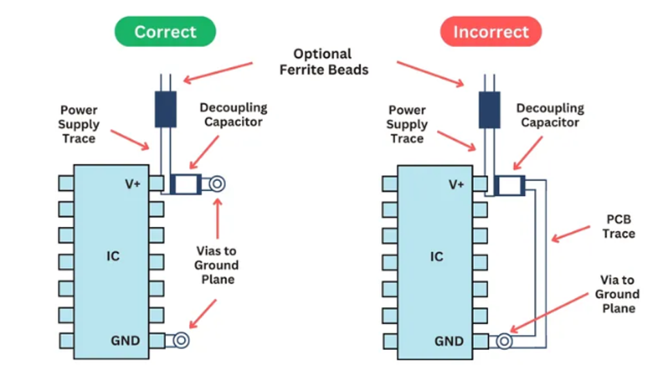
Placement and Layout Guidelines
Proper layout is crucial. Here are the best practices:
Place capacitors close to the load – Keep traces short and connect decoupling capacitors directly between the power pin and ground pin of the IC. Shorter loops minimize parasitic inductance and reduce the effective ESL.
Use multiple vias and wide traces – Provide low‑impedance connections by using several vias in parallel and wide copper pours. This also spreads current and reduces inductance.
Alternate capacitor orientation – For identical surface mount capacitors, alternating orientation can reduce mutual inductance and mitigate anti‑resonance.
Distribute capacitors across planes – Use power and ground planes placed close together to increase distributed capacitance and lower impedance.
Group by function – For multi‑rail systems, decouple each voltage rail separately. Placing all decoupling capacitors at one location defeats the purpose.
Suggested Reading: Decoupling Capacitors: Mastering Power Integrity in Electronic Design
Avoiding Resonance and Anti‑Resonance
Combining capacitors of different values introduces resonances where the net impedance drops or peaks. Anti‑resonance occurs when the interaction between capacitors and their parasitic inductances produces a sharp peak in impedance, which can amplify noise. To minimize these effects:
Use identical values and packages for groups of parallel capacitors when possible, as this reduces mismatches in inductance and capacitance.
Spread values over decades (e.g., 1 µF, 0.1 µF, 0.01 µF) to avoid resonances clumping together.
Place smaller capacitors physically closer to the IC pins than larger ones, ensuring that high‑frequency loops remain minimal.
Simulate the PDN impedance with tools like SPICE or dedicated PDN simulators to locate and dampen resonance peaks.
Energy Storage and Supercapacitors in Parallel
Beyond decoupling, designers use parallel capacitors for energy storage. Large capacitor banks can deliver bursts of current in power supplies or act as hold‑up energy sources. Supercapacitors or electrochemical double‑layer capacitors (EDLCs) provide farads of capacitance.
To increase total energy, multiple supercapacitors are often connected in parallel to reach the required current delivery while keeping ESR low.
When designing supercapacitor banks:
Match capacitor characteristics – Use the same model and batch to ensure similar ESR and leakage.
Balance cells – If connected in series to increase voltage, include active or passive balancing circuits to equalize voltage across cells. In pure parallel configurations, balancing is less critical, but series modules often require balancing.
Consider safety – Supercapacitors can deliver large currents; ensure that connectors and traces can handle the surge, and include fuses or protection circuits.
Supercapacitor banks are used in uninterruptible power supplies (UPS), regenerative braking systems, and memory backup for real‑time clocks. They illustrate another domain where parallel capacitance is crucial.
Practical Example 1: Decoupling a Microcontroller Board
Let's design the power decoupling for a microcontroller running at 48 MHz from a 3.3 V supply. The board uses a linear regulator followed by the microcontroller and a few peripheral ICs. Our goals are to maintain a stable 3.3 V across the microcontroller during operation and to suppress noise that could interfere with the analog-to-digital converter (ADC).
Step 1: Identify Current Profiles
The datasheet shows that the microcontroller draws bursts of up to 100 mA during operation. Peripheral ICs draw another 20 mA. The 3.3 V regulator can supply 500 mA, so average loading is moderate, but the transient current during clock edges is critical.
Step 2: Select Bulk Capacitance
Place a 10 µF tantalum capacitor near the regulator output to handle low‑frequency ripple and supply droop. Tantalum offers better ESR than electrolytics at this value and voltage rating.
Step 3: Distribute Ceramic Capacitors
Place a 4.7 µF MLCC near the microcontroller. Add several 0.1 µF MLCCs close to each supply pin. Because the microcontroller may have multiple power pins (e.g., VDD and VDDA for analog), each pin gets its own capacitor.
Step 4: Lay Out the Board
Position the 0.1 µF capacitors adjacent to the power pins with the shortest possible traces. Use wide copper pours for VDD and ground to minimize resistance and inductance. Place the 4.7 µF capacitor slightly further away but still within a few millimeters. The 10 µF can be near the regulator but still on the same plane.
Step 5: Simulate and Verify
Use a PDN simulation tool or SPICE to model the decoupling network. Check impedance profiles across frequency. Adjust capacitor values and placement to minimize peaks. In measurement, use an oscilloscope with a high‑bandwidth probe to observe the supply ripple while the microcontroller toggles. If noise is still problematic, add 1 µF MLCC or a ferrite bead as necessary.
Step 6: Monitor Temperature and Aging
Capacitors change their characteristics with temperature and age. MLCCs can exhibit capacitance reduction at high DC bias (voltage coefficient), while tantalums can fail catastrophically if overstressed. Provide a margin in the voltage rating and monitor the board under environmental conditions to ensure reliability.
By following these steps, you build a robust decoupling network using parallel capacitors, ensuring stable operation of the microcontroller and its peripherals.
Suggested Reading: Microcontroller-Based IoT Development Kits: Powering the Next Generation of IoT Solutions
Practical Design Example 2: FPGA Power Rail
Consider a field‑programmable gate array (FPGA) operating at 1.0 V with a maximum current of 10 A and switching frequencies up to 500 MHz. To design an effective decoupling network:
Step 1 - Estimate Required Decoupling Capacitance
Use the relationship.
ΔV = ΔI · dt / C,
where ΔV is the maximum allowable ripple (e.g., 50 mV), ΔI is the transient current (assume 2 A), and dt is the switching edge duration (e.g., 1 ns). When we rearrange,
C = ΔI · dt / ΔV = 2 A × 1 ns / 0.05 V = 40 nF.
Because transients occur across multiple frequencies, multiply by a safety factor (e.g., ×10), so you may aim for 400 nF of high‑frequency ceramic capacitors distributed around the FPGA.
Step 2 - Select capacitor values
Choose four 100 nF C0G capacitors near each FPGA power pin. Add two 4.7 µF X7R capacitors for mid‑frequency decoupling and one 100 µF tantalum capacitor near the voltage regulator.
Step 3 - Placement
Position the 100 nF capacitors as close as possible to each power ball on the BGA package. Use the via in the pad to connect directly to the inner planes. Place the 4.7 µF capacitors a few millimeters away on the same layer, and the bulk capacitor near the regulator, but still on the same plane pair.
Step 4 - Check impedance profile
Use simulation tools (e.g., SPICE, PDN analyzers) to model the impedance across frequency. Adjust capacitor values and positions to flatten peaks and avoid anti‑resonance.
Step 5 - Validate with Measurement
After assembly, measure the supply noise using an oscilloscope and adjust if necessary by adding or moving capacitors.
Recommended Reading: CPLD vs FPGA: A Comprehensive Technical Analysis and Implementation Guide
Advanced Considerations
The Impact of ESL and ESR on Parallel Networks
At high frequencies, the inductive reactance of a capacitor's leads and internal structure becomes significant. The impedance of a real capacitor is:

where j is the imaginary unit, and ω is the angular frequency. When multiple capacitors are paralleled, ESR and ESL combine in parallel just like resistors and inductors, lowering the total ESR and ESL. However, if the values differ significantly, the network may exhibit anti‑resonance. Engineers use simulation to predict these effects and choose values that produce a smooth impedance profile.
Temperature and Voltage Dependence
Capacitors vary with temperature, applied DC bias, and frequency. Ceramic capacitors with class II dielectrics (X7R, X5R, etc.) can lose 60 % of their nominal capacitance at rated voltage.
When building parallel networks, consider this loss; choose class I ceramics (C0G/NP0) or film capacitors for precision, though they come in smaller values. Electrolytic capacitors have a high negative temperature coefficient and may fail at cold temperatures if their electrolyte freezes. Always consult datasheets and derate appropriately.
Reliability and Failure Modes
Parallel capacitors increase reliability through redundancy: if one capacitor fails open, others still provide decoupling. However, catastrophic failures such as short circuits in tantalum capacitors can short out the power rail.
Fuses, polyswitches, or protection circuits may be necessary for high‑energy applications. For safety‑critical systems, perform failure mode and effects analysis (FMEA) and use capacitors with fail‑safe designs.
Aging and Failure Mechanisms
Tantalum capacitors can fail short due to dielectric breakdown; electrolytic capacitors dry out over time, increasing ESR and reducing capacitance. Ceramic capacitors can crack under mechanical stress or due to thermal cycling. To enhance reliability:
Use multiple capacitors in parallel to share stress. Even if one fails, the remaining capacitors maintain functionality.
Avoid mechanical stress by adhering to recommended land patterns and assembly guidelines.
Perform life testing under expected temperature and voltage conditions.
Conclusion
Connecting capacitors in parallel is a key technique in electronics to increase total capacitance, reduce impedance, and stabilize power distribution. This is crucial for applications like microcontroller decoupling, amplifier supply smoothing, and supercapacitor banks. Understanding the mathematics, along with the behavior of equivalent series resistance (ESR) and inductance (ESL), helps achieve broadband performance using multiple capacitor values.
Practical layout guidelines focus on minimizing parasitics and avoiding anti-resonance, while case studies show that optimized decoupling improves signal rise times, reduces jitter, and lowers noise. Mastering these principles enables better designs, supported by simulation tools and datasheet consultation, resulting in clean, stable power and more reliable circuits.
Frequently Asked Questions (FAQ)
What is the difference between connecting capacitors in series and in parallel?
In series, the total capacitance decreases because the effective plate separation increases; the voltage divides across each capacitor. In parallel, the plates’ areas add, so capacitance increases. Use series connections to handle higher voltages and parallel connections to increase capacitance.
Why do designers use different values of capacitors in parallel?
No single capacitor maintains low impedance over all frequencies. Large electrolytic capacitors filter low‑frequency noise but become inductive at high frequencies; small ceramics handle high frequencies but have limited capacitance. Combining values provides low impedance across the spectrum.
How close should decoupling capacitors be placed to IC pins?
As close as physically possible—ideally adjacent to the power and ground pins. This minimises loop inductance and ensures the capacitor supplies current before the power rail droops.
Is there energy loss when connecting charged capacitors in parallel?
Yes. When a charged capacitor is connected to an uncharged one, half of the initial energy is dissipated as heat or electromagnetic radiation, even if the series resistance is very low. Designers should avoid directly connecting capacitors with large voltage differences; instead, pre‑charge them to similar voltages or use controlled charging circuits.
What is the difference between a decoupling capacitor and a bypass capacitor?
These terms are often used interchangeably. Both serve to provide a low‑impedance path to ground for AC noise while maintaining DC supply voltage. Some practitioners differentiate by frequency: bypass capacitors shunt high‑frequency noise to ground, while decoupling capacitors store energy to supply sudden load changes.
How many capacitors should be used in parallel?
There is no universal number. Use enough high‑frequency capacitors to meet your impedance target and enough bulk capacitance for low‑frequency stability. Simulation and measurement guide the final count. Avoid excessive numbers that introduce anti‑resonant peaks.
Can supercapacitors replace batteries?
Supercapacitors offer high power density and long cycle life but have lower energy density than batteries. They are excellent for short‑term energy storage, regenerative braking and buffering power peaks. Combining supercapacitors in parallel increases energy storage, but designers must manage leakage and balancing.
References
“Basic Electronics Tutorials and Revision.” Electronics-Tutorials.ws. [Online]. Available: https://www.electronics-tutorials.ws
“Setup and Using MicroPython for Beginners.” Learn.SparkFun.com. [Online]. Available: https://learn.sparkfun.com
“Mastering EMI Control in PCB Design: Decoupling Strategies for PDN.” Altium Resources. [Online]. Available: Mastering EMI Control in PCB Design: Decoupling Strategies for PDN | Altium
“Low ESR Capacitors Increase Power Integrity.” VSE Corporation Blog, May 8, 2024. [Online]. Available: https://www.vse.com/blog/2024/05/08/low-esr-capacitors-increase-power-integrity/
“Multi Layer Ceramic Capacitor Market.” Precedence Research. 2025. [Online]. Available: https://www.precedenceresearch.com/multi-layer-ceramic-capacitor-market
“4.2.1 Decoupling Capacitors.” Microchip Documentation. [Online]. Available: https://onlinedocs.microchip.com/oxy/GUID-F2693295-804D-4E36-8BA5-0105C1751EA5-en-US-8/GUID-65D70C85-0378-4DFD-83FE-D16BFB33A63C.html
in this article
1. Key Takeaways2. Introduction3. Fundamentals of Capacitance4. Capacitors in DC and AC Circuits5. Why Connect Capacitors in Parallel?6. Calculating Equivalent Capacitance in Parallel7. Electrical Behavior and Impedance8. Applications in Digital and Power Electronics: Decoupling and Bypass Networks9. Energy Storage and Supercapacitors in Parallel10. Practical Example 1: Decoupling a Microcontroller Board11. Practical Design Example 2: FPGA Power Rail12. Advanced Considerations13. Conclusion14. Frequently Asked Questions (FAQ)15. References