Active High Pass Filter: Theory, Design, and Applications
Active high-pass filters remove unwanted low-frequency signals while preserving useful higher frequencies. This article covers first- and second-order filter design, Sallen-Key and multiple-feedback topologies, and practical applications in audio electronics, instrumentation, and signal processing.

26 May, 2026. 13 minutes read
Key Takeaways
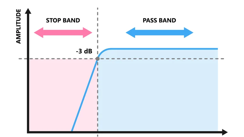
An active high-pass filter combines an operational amplifier with resistor and capacitor networks to block low-frequency signals while amplifying higher frequencies.
Unlike a passive high-pass filter, active designs provide amplification, higher input impedance, lower output impedance, and better control over the filter's frequency response.
A first-order filter has the transfer function H(s) = K(sRC) / (1 + sRC). The cutoff frequency is: fc = 1 / (2πRC)
Sallen-Key active high-pass filter circuits are popular because they provide stable unity gain or moderate voltage gain using a simple non-inverting amplifier configuration.
Multiple-feedback topologies are commonly used when sharper attenuation, higher-order responses, or high-Q frequency response characteristics are required.
Butterworth filters maximize flatness, Chebyshev filters improve transition sharpness, and Bessel filters preserve waveform accuracy and minimize phase shift.
Proper op-amp selection is critical. The amplifier bandwidth and slew rate must support the desired bandwidth and frequency response.
Active high-pass filters are widely used in audio electronics, sensor interfaces, communication systems, bandpass filter stages, and analog signal conditioning.
Introduction
An active high-pass filter (HPF) is an electronic filter that allows signals above a specific cutoff frequency to pass while attenuating lower-frequency components. These filter circuits are essential in analog systems because they remove DC offsets, suppress unwanted low-frequency noise, and improve signal clarity before amplification or digital conversion. In a passive high-pass filter, the response is created using passive components such as a resistor, a capacitor, and sometimes inductors. While passive RC filter designs are simple, they suffer from loading effects and cannot provide voltage gain. An active high-pass filter overcomes these limitations by integrating an op-amp or operational amplifier into the circuit design. The amplifier stage provides amplification, improves impedance matching, and stabilizes the output signal during cascading between stages.
A useful way to understand HPF behavior is through duality. The active high-pass filter is effectively the inverse of the active low-pass filter. In many Sallen-Key and multiple-feedback topologies, swapping resistor and capacitor positions converts a low-pass filter into a high-pass configuration. This makes HPF filter design easier for engineers already familiar with low-pass filter architectures. Active HPFs are commonly used in audio systems, instrumentation, communication electronics, and sensor interfaces where low-frequency attenuation is required without sacrificing higher frequencies. They also form the foundation of many bandpass and bandpass filter circuits used in analog signal-processing systems.
Recommended reading: Active Bandpass Filter Design Guide
Active vs Passive High-Pass Filters
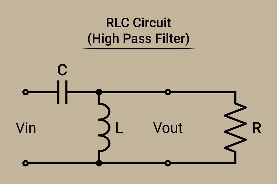
A passive high-pass filter uses only passive components, such as a capacitor and a resistor, to block low-frequency signals. In the simplest RC filter arrangement, the capacitor is connected in series with the input signal, while the resistor connects to ground. At low frequencies, the capacitor impedance is high, which reduces signal transfer. At higher frequencies, capacitor impedance decreases, allowing the output signal amplitude to rise. Although passive designs are inexpensive and simple, they introduce several limitations. The cutoff frequency changes when source or load impedance varies, and the circuit cannot provide amplification because there is no active amplifier stage. In addition, steep attenuation slopes often require inductors, which become physically large and inefficient in low-frequency applications.
An active high-pass filter eliminates many of these problems. By using an op-amp in combination with resistor-capacitor networks, the circuit achieves stable voltage gain, better impedance isolation, and improved frequency response control. The high input impedance of the operational amplifier prevents loading of the input signal source, while the low output impedance simplifies cascading with additional electronic filters. Another important benefit is DC blocking. Since capacitors naturally block direct current, active HPFs are widely used between amplifier stages with different DC bias levels. In audio systems, for example, an active high-pass filter removes unwanted low-frequency hum while preserving useful high-frequency audio content.
Despite their advantages, active filters still have practical limitations. The op-amp bandwidth, power supply range, and slew rate affect the filter's frequency response. At very high-frequency operation, passive LC designs may outperform active circuits because the amplifier can oscillate or lose stability when bandwidth becomes insufficient.
Recommended reading: Active Low Pass Filter Design and Implementation Wide-Band Bandpass: Cascaded High-Pass and Low-Pass Filters
First-Order Active High Pass Filter
A first-order filter is the simplest active high-pass filter configuration. It uses a capacitor connected in series with the input voltage and a resistor tied to ground. The RC network feeds the non-inverting amplifier input of the op-amp, while feedback resistors determine the closed-loop voltage gain. This filter circuit operates by exploiting the frequency-dependent impedance of the capacitor. At low-frequency operation, the capacitor blocks much of the input signal, creating strong attenuation. As frequency increases, capacitor impedance decreases, and the signal passes more easily through the amplifier stage.
The transfer function of the circuit is:
H(s) = K(sRC) / (1 + sRC)
where:
K is the voltage gain of the amplifier,
R is the resistor value,
C is the capacitor value,
and s represents the complex frequency variable.
The cutoff frequency occurs at:
fc = 1 / (2πRC)
At frequencies below the cutoff frequency, the roll-off rate is 20 dB per decade. Above the cutoff point, the frequency response becomes relatively flat and approaches the passband voltage gain set by the op-amp feedback network.
The phase shift of the filter changes with frequency. At very low-frequency operation, the output leads the input signal by nearly 90 degrees. As the frequency rises well above the cutoff frequency, the phase shift gradually approaches 0 degrees.
An alternative configuration uses the op-amp in an inverting arrangement. In this design, the capacitor is placed in series with the input resistor leading to the inverting input. The resulting output signal is inverted by 180 degrees relative to the input voltage, but the overall attenuation behavior remains similar.
First-order active HPFs are commonly used for:
audio AC coupling,
sensor signal conditioning,
microphone preamplifiers,
and analog front-end filtering applications.
Compared with second-order filters, a first-order filter provides gentler attenuation and simpler circuit design, making it suitable for systems where moderate low-frequency rejection is acceptable.
Recommended reading: Operational Amplifier: Theory, Design and Applications for Engineers
Second-Order Topologies
A second-order active high-pass filter delivers a steeper roll-off rate than a first-order filter, making it more effective at rejecting unwanted low-frequency noise and DC offsets. While a first-order RC filter attenuates signals at 20 dB per decade, second-order filters increase attenuation to 40 dB per decade below the cutoff frequency. This sharper frequency response is especially useful in audio electronics, instrumentation, communications systems, and sensor conditioning circuits where precise filtering is required.
Most second-order filters use an op-amp combined with passive components such as resistors and capacitors. The operational amplifier provides voltage gain, buffering, impedance isolation, and improved filter stability. Two of the most widely used topologies are the Sallen-Key configuration and the Multiple Feedback (MFB) configuration. Both are standard approaches in analog filter design and are commonly used in active high-pass filter circuits because they provide predictable bandwidth control and accurate frequency shaping.
Sallen-Key High Pass Filter
The Sallen-Key topology is one of the most popular active high-pass filter designs because it is simple, stable, and easy to implement. In this filter circuit, the op-amp usually operates as a voltage follower or non-inverting amplifier. Two capacitors are placed in series with the input signal path, while two resistors connect to ground, creating the filter’s frequency response. A major advantage of the Sallen-Key topology is its simplicity. Since the operational amplifier can operate at unity gain, the circuit requires fewer adjustments and is easier to tune than more complex electronic filters. The design also offers high input impedance and low output impedance, making cascading between stages straightforward.
The cutoff frequency of a second-order Sallen-Key active high-pass filter is determined by both the resistor and capacitor values:
fc = 1 / (2π√(R1 × R2 × C1 × C2))
When equal-value components are selected, the equation becomes easier to use:
fc = 1 / (2πRC)
The quality factor Q determines the sharpness of the filter's frequency response around the cutoff frequency. In equal-component Sallen-Key circuits:
Q = 1 / (3 − K)
where K is the voltage gain of the non-inverting amplifier stage.
For a Butterworth response, which provides a maximally flat amplitude response, the required gain is approximately 1.586. Increasing voltage gain increases Q and can cause the circuit to oscillate if the design becomes unstable. Designers must therefore balance amplification, bandwidth, and stability carefully. Sallen-Key active high-pass filter circuits are widely used in audio processing, analog signal conditioning, instrumentation amplifiers, and bandpass filter stages. They are especially useful when moderate Q values and clean frequency response characteristics are required.
Recommended reading: Inverting vs Non-Inverting Op Amp: Complete Design Guide & Best Practices 2025
Multiple Feedback (MFB) High Pass Filter
The multiple feedback topology is another widely used active high-pass filter configuration. Unlike the Sallen-Key design, the MFB filter uses the op-amp in an inverting configuration. This topology employs multiple resistors and capacitors connected through the amplifier feedback network to create the desired filter response. An important advantage of the MFB topology is its ability to achieve high Q values without requiring excessive amplifier gain. Because the operational amplifier output experiences smaller signal swings near the band edge, distortion is reduced compared to some Sallen-Key implementations. MFB filters are therefore commonly used in higher-order filter systems and precision analog applications.
The MFB topology is especially useful in communications equipment, active crossover systems, and precision measurement instruments where strong attenuation below the cutoff frequency is necessary. Since the design can achieve narrow bandwidth operation more effectively, it is commonly used in bandpass and active high-pass filter applications that require steep filtering characteristics. However, the circuit is more sensitive to resistor tolerances and capacitor value matching. Careful filter design and simulation are important to ensure stable operation and predictable performance.
Filter Response Types
The response characteristics of an active high-pass filter depend heavily on pole placement and topology. Engineers typically choose between Butterworth, Chebyshev, and Bessel responses depending on the desired balance between attenuation, bandwidth, phase shift, and transient behavior. A Butterworth active high-pass filter provides a maximally flat passband response. This means the amplitude remains smooth across the useful frequency range with no ripple. Butterworth filters are among the most commonly used electronic filters because they offer balanced performance between roll-off rate and stability. They are ideal for audio systems, instrumentation, and general-purpose analog circuits.
A Chebyshev response provides a much steeper transition near the cutoff frequency. This sharper attenuation improves rejection of unwanted low-frequency components, but it introduces ripple in the passband and increased phase shift. Chebyshev filters are useful when stronger selectivity is more important than waveform accuracy.
Bessel filters prioritize waveform fidelity and linear phase response. Although the attenuation near cutoff is gentler, Bessel filters preserve transient signals better than Butterworth or Chebyshev designs. This makes them ideal for pulse circuits, measurement systems, and data communications where timing accuracy matters. The quality factor Q strongly influences how the filter behaves near cutoff. Higher Q values create sharper transitions and may introduce peaking or ringing in the output signal. Lower Q values reduce overshoot and improve stability.
Recommended reading: Transistor Circuits: Theory, Types, and Practical Applications
Cutoff Frequency, Gain, and Q Factor
The cutoff frequency defines the point where the active high-pass filter begins passing higher frequencies while attenuating low-frequency signals. In practical filter design, this is normally defined as the frequency where the output amplitude falls by 3 dB relative to the passband level.
The general transfer function for a second-order active high-pass filter is:
H(s) = K × s² / (s² + (sω0 / Q) + ω0²)
where:
K represents voltage gain
ω0 represents angular cutoff frequency
Q represents the quality factor
The frequency response of the filter depends on all three variables. Increasing Q sharpens the transition between passband and stopband regions, while increasing voltage gain raises overall signal amplification.
The relationship between cutoff frequency, resistor selection, and capacitor value is extremely important in analog circuit design. Even small component variations can shift the filter's frequency response significantly. Precision resistor matching and stable capacitor materials help maintain predictable performance over temperature and time.
Designers often simulate filter behavior before building hardware. Simulation tools allow engineers to analyze amplitude response, bandwidth, attenuation, phase shift, and potential instability before selecting final component values.
Higher-Order Filters
When stronger attenuation or steeper roll-off is required, engineers create higher-order filters by cascading multiple first-order filters and second-order filters together. Each stage contributes additional attenuation and modifies the overall filter's frequency response. For example, a fourth-order active high-pass filter may consist of two cascaded Sallen-Key stages. A sixth-order design may combine multiple MFB and Sallen-Key sections. Cascading allows designers to achieve extremely sharp stopband rejection while maintaining stable operation.
Higher-order active high-pass filter circuits are widely used in communication systems, precision instrumentation, medical electronics, and digital conversion systems where low-frequency interference must be removed aggressively. Some advanced topologies also generate multiple outputs simultaneously. State-variable filters and universal filter circuits can provide low-pass filter, active high-pass filter, and bandpass filter outputs within the same schematic. These versatile designs are common in analog synthesizers, measurement equipment, and adaptive filter systems.
Recommended reading: Low Pass Filter vs High Pass Filter – Theory, Design, and Applications
Op-Amp Selection
The performance of an active high-pass filter depends heavily on the op-amp used in the design. Even a well-designed filter circuit can fail if the operational amplifier lacks sufficient bandwidth, slew rate, or stability. The gain-bandwidth product is one of the most important specifications. The op-amp bandwidth should typically be at least 100 times greater than the target cutoff frequency to preserve the intended frequency response accurately. Insufficient bandwidth reduces attenuation accuracy and can distort the filter's frequency response.
Slew rate is equally important in high-frequency applications. If the op-amp cannot respond fast enough to rapid changes in the input signal, distortion occurs. High-speed audio amplifiers and communications systems, therefore, require op-amps with high slew rates and wide bandwidth. Input impedance, output impedance, and power supply limitations must also be considered carefully. Rail-to-rail operational amplifier devices are commonly selected for low-voltage analog systems because they maximize dynamic range and improve signal handling.
Texas Instruments, Analog Devices, and other semiconductor manufacturers provide dedicated op-amp tutorials and filter design resources that simplify active filter implementation.
Recommended reading: Difference Amplifier: Theory, Design, and Applications for Engineers
Design Example: Audio Coupling at 100 Hz
To understand how an active high-pass filter works in practice, consider a real-world audio coupling application. In many amplifier and analog audio systems, unwanted low-frequency signals, DC offsets, and rumble noise must be removed before amplification. A second-order Sallen-Key active high-pass filter is commonly used because it combines stable frequency response, low distortion, and simple implementation.
In this example, the goal is to design a Butterworth active high-pass filter with a cutoff frequency of 100 Hz and approximately unity gain. A Butterworth response is selected because it provides a smooth amplitude response with no ripple in the passband, making it ideal for audio applications. The design uses a Sallen-Key topology with equal resistor and capacitor values. This approach simplifies filter design calculations while maintaining excellent performance.
Recommended reading: Implementing Audio Event Detection on the Edge with Particle Photon 2
Step 1: Select the capacitor value
The first step is selecting a practical capacitor value. In audio-frequency active filter circuits, capacitor sizes should balance physical size, cost, and noise performance.
Choose:
C1 = C2 = 100 nF
This capacitor value is widely available and works well for low-frequency audio filtering. Using equal capacitors simplifies the design equations and improves matching accuracy in the filter circuit.
Step 2: Calculate the Resistor Value
For an equal-component Sallen-Key active high-pass filter, the cutoff frequency equation is:
fc=12πRCf_c=\frac{1}{2\pi RC}fc=2πRC1
Rearranging the formula to solve for the resistor:
R=12πfcCR=\frac{1}{2\pi f_c C}R=2πfcC1
Substituting the design values:
Cutoff frequency = 100 Hz
Capacitor value = 100 nF
The result becomes:
R ≈ 15.9 kΩ
The nearest standard resistor value is:
R1 = R2 = 16 kΩ
Using these resistor values gives an actual cutoff frequency very close to the target:
fc ≈ 99.5 Hz
This small variation is completely acceptable in most analog audio systems.
Step 3: Set the Gain for a Butterworth Response
The quality factor Q determines how sharp the filter’s frequency response becomes around the cutoff frequency. For a Butterworth response:
Q=12≈0.707Q=\frac{1}{\sqrt{2}}\approx0.707Q=21≈0.707
In a Sallen-Key active high-pass filter with equal components:
Q=13−KQ=\frac{1}{3-K}Q=3−K1
Solving for voltage gain K:
K ≈ 1.586
The op-amp, therefore, operates as a non-inverting amplifier with modest amplification. The gain is set using the resistor feedback network:
K=1+R4R3K=1+\frac{R4}{R3}K=1+R3R4
Selecting:
R3 = 10 kΩ
R4 ≈ 5.9 kΩ
produces the required voltage gain for the Butterworth response. A standard 5.6 kΩ resistor is usually acceptable in practical filter design.
At this stage, the active high-pass filter provides smooth low-frequency attenuation, stable bandwidth, and excellent audio response characteristics.
Step 4: Verify the Frequency Response
Before building the circuit physically, engineers normally verify the filter's frequency response using simulation software such as SPICE. Simulation allows designers to examine attenuation, phase shift, amplitude response, and bandwidth before assembling hardware.
The expected response should show:
A cutoff frequency near 100 Hz
A second-order roll-off rate of 40 dB per decade
Flat Butterworth response above cutoff
Strong attenuation of low-frequency noise below the passband
Simulation also helps identify instability issues that may cause the op-amp to oscillate. Small changes in resistor tolerance or capacitor value can slightly shift the cutoff frequency, so simulation improves design accuracy significantly.
Recommended reading: An Introduction to RF Theory, Practices, and Components
Component Summary
The completed active high-pass filter uses the following components:
Component | Value | Purpose |
C1, C2 | 100 nF | Capacitors in the signal path |
R1, R2 | 16 kΩ | Set the cutoff frequency |
R3 | 10 kΩ | Feedback resistor |
R4 | 5.6–5.9 kΩ | Sets voltage gain |
Op-amp | Low-noise audio amplifier | Active filtering and buffering |
This filter circuit is ideal for audio amplifiers, active crossover systems, AC coupling stages, and low-frequency noise rejection.
Conclusion
An active high-pass filter is one of the most important building blocks in analog electronics. By combining an op-amp with resistor and capacitor networks, engineers can create compact filter circuits that provide amplification, impedance isolation, precise frequency response, and strong low-frequency attenuation without relying on bulky inductors.
First-order filters provide gentle filtering characteristics, while second-order filters, such as Sallen-Key and Multiple Feedback topologies, offer steeper attenuation and improved selectivity. Butterworth, Chebyshev, and Bessel responses allow designers to tailor bandwidth, phase shift, and stopband performance for specific applications.
Because active high-pass filter circuits can be cascaded easily, they are widely used in higher-order audio systems, communications equipment, instrumentation, and signal-processing electronics. They are also commonly paired with an active low-pass filter to create bandpass filter networks and advanced electronic filters. Successful filter design ultimately depends on selecting the correct operational amplifier, resistor values, capacitor value, and cutoff frequency for the intended application. Careful simulation and testing help ensure stable amplification, clean output signal performance, and reliable analog operation.
Frequently Asked Questions (FAQ)
What is an active high-pass filter?
An active high-pass filter is a filter circuit that uses an op-amp together with resistors and capacitors to pass higher frequencies while attenuating low-frequency signals. Unlike a passive high-pass filter, it can provide voltage gain and impedance isolation.
How does an active high-pass filter differ from a passive one?
A passive high-pass filter only uses passive components such as capacitors, resistors, and sometimes inductors. An active high-pass filter adds an operational amplifier, allowing amplification, improved impedance characteristics, and easier cascading between stages.
Why are Sallen-Key filters popular?
Sallen-Key filters are popular because they are simple, stable, and easy to design. They work well in audio amplifier circuits, analog signal conditioning, and second-order filters with moderate Q values and unity gain operation.
What determines the cutoff frequency?
The cutoff frequency depends on the resistor and capacitor values in the RC filter network. In equal-component Sallen-Key designs:
fc=12πRCf_c=\frac{1}{2\pi RC}fc=2πRC1
What is the role of the op-amp?
The op-amp acts as an amplifier and buffer. It provides amplification, isolates the input signal from loading effects, improves output impedance, and preserves the filter's frequency response during cascading.
What is the difference between Butterworth, Chebyshev, and Bessel responses?
Butterworth filters provide flat amplitude response, Chebyshev filters offer steeper attenuation with ripple, and Bessel filters preserve waveform shape with minimal phase shift. The correct choice depends on whether the application prioritizes bandwidth, stopband attenuation, or transient accuracy.
Can active high-pass filters be combined with other filters?
Yes. Active high-pass filter stages are commonly combined with low-pass filter stages to create bandpass circuits, crossover networks, and advanced analog signal-processing systems.
References
“Op Amp Active Filter Design,” sysidguy.eu, accessed May 23, 2026. [Online]. Available: https://sysidguy.eu/regeltechniek/opamp_filter_design.pdf
R. Mancini, Op Amps for Everyone, 4th ed. Dallas, TX, USA: Texas Instruments, 2009. [Online]. Available: https://web.mit.edu/6.101/www/reference/op_amps_everyone.pdf [Accessed: May 23, 2026].
"Low Pass Filter vs High Pass Filter—Theory, Design, and Applications,” Wevolver, 2025. [Online]. Available: https://www.wevolver.com/article/low-pass-filter-vs-high-pass-filter-theory-design-and-applications [Accessed: May 23, 2026].
R. Schaumann and M. E. Van Valkenburg, Design of Analog Filters, New York, NY, USA: Oxford University Press, 2001.
Wevolver, “Operational Amplifier: Theory, Design and Applications for Engineers,” Wevolver, 2025. [Online]. Available: https://www.wevolver.com/article/operational-amplifier-theory-design-and-applications-for-engineers [Accessed: May 23, 2026].
in this article
1. Key Takeaways2. Introduction3. Active vs Passive High-Pass Filters4. First-Order Active High Pass Filter5. Second-Order Topologies6. Filter Response Types7. Cutoff Frequency, Gain, and Q Factor8. Higher-Order Filters9. Op-Amp Selection10. Design Example: Audio Coupling at 100 Hz11. Conclusion12. Frequently Asked Questions (FAQ)13. References