Renesas Electronics ForgeFPGA™ Socket Card Development Kits
Prototyping Platform for ForgeFPGA™ Configuration Testing
General
| Product Type | Prototyping Kits |
| Applications | Prototyping & Development, Configuration Testing, Consumer Electronics |
| Key Features | Onboard 4 Mbit SPI Flash, Onboard Clock Generator, 2.5 kHz to 200 MHz |
Technical Specifications
| Platform Interface | Connection between ForgeFPGA™ device & Go Configure DB |
| Configuration Storage | Onboard 4 Mbit SPI Flash |
| Clock Source | Onboard Clock Generator |
| Clock Frequency Range | 2.5 kHz to 200 MHz |
| Expansion Interface | Pmod Connectors for Pmod Adapters |
| Boot Modes | Supports Standalone Boot Option |
| Power Input | Standalone Power Connectors |
| Applications | Data Communications Equipment, Handheld & Portable Electronics, Industrial Instrumentation |
Overview
The Renesas Electronics ForgeFPGA™ Socket Card Development Kits provide a hardware interface between ForgeFPGA devices and the Go Configure Development Board for prototyping and configuration testing. These kits enable direct pin connectivity between the FPGA and the development platform, allowing evaluation of device functionality across different boot modes. The socket cards integrate an onboard 4 Mbit SPI Flash for configuration storage and a clock generator with a programmable frequency range from 2.5 kHz to 200 MHz, supporting timing validation in various FPGA applications.
The kits include Pmod connectors that allow the attachment of Pmod-compatible adapters to expand peripheral functionality. Programming and emulation are supported through the development board interface, enabling configuration testing and debugging during the design process. Additional standalone power connectors enable independent operation during evaluation. Each development kit includes a socket card, 20 device samples, and a Pmod LED adapter, allowing engineers to perform initial FPGA configuration experiments and interface verification.
Features of ForgeFPGA Socket Card Development Kits
The ForgeFPGA Socket Card Development Kits provide interfaces, configuration storage, clock generation, and expansion connectivity for FPGA prototyping. Let’s go through their features in detail:
FPGA Interface and Prototyping Support
The ForgeFPGA Socket Card Development Kits provide a direct connection between the pins of a ForgeFPGA device and the Go Configure Development Board. This interface allows designers to prototype and evaluate FPGA configurations while supporting different boot modes available on the development platform. The setup enables functional testing of device pin mappings and signal routing during early design stages.
Programming and Boot Configuration
The kits support programming and emulation through the development environment, enabling configuration loading and functional verification of FPGA designs. A standalone boot option is also available, allowing the FPGA to operate independently without relying on the host development board during evaluation.
Memory and Clock Generation
Each socket card integrates 4 Mbit SPI flash for storing configuration data and design images. The board also includes an onboard clock generator capable of producing frequencies from 2.5 kHz to 200 MHz, supporting timing evaluation and clock source testing across different FPGA applications.
Expansion and Power Interfaces
The socket cards include Pmod connectors compatible with the Pmod standard, enabling connection of external Pmod adapters and peripheral modules. Standalone power connectors allow independent operation during testing. Each kit includes a socket card, 20 device samples, and a Pmod LED adapter for basic I/O verification.
Applications
The ForgeFPGA Socket Card Development Kits are used for prototyping and evaluating FPGA-based designs across multiple electronic systems. In consumer electronics, they support the development of configurable logic for device control and signal processing. For data communications equipment, the kits allow testing of FPGA configurations used in interface management and protocol handling. In handheld and portable electronics, they enable evaluation of compact programmable logic solutions for power-efficient processing. The kits are also applicable in notebooks and tablet PCs, where FPGA devices can support specialized control or interface functions. In industrial instrumentation and control, the platform assists in validating FPGA logic for monitoring, automation, and data acquisition systems.
Where to find it

Mouser Electronics
Mouser Electronics is a worldwide leading authorized distributor of semiconductors and electronic components.
References


Continue Reading
This article presents a comprehensive engineering guide to Hall Effect Sensors, covering theoretical foundations, device structures, sensor types, specifications, applications, and practical integration strategies for modern electronic system design.
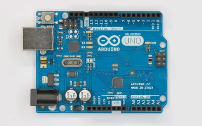
This article covers every aspect of the Arduino UNO pinout, presenting a technical, pin-by-pin explanation to help readers confidently design, analyze, and implement Arduino-based systems.
UART and SPI are key communication methods in electronics. UART is ideal for simple, long-distance connections, while SPI excels in fast data transfer. Used in GPS modules, SD cards, and microcontrollers, understanding their differences can help you choose the best for any given project.