Cubli
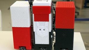
The Cubli is a one degree of freedom robot that can jump up and balance on its corner.
Technical Specifications
| Height | 15 |
| Width | 15 |
| Length | 15 |
| Controller | |
| IMU (inertial measurement unit ) | 6 |
| DC motor | 3 |
Overview
The reaction wheels mounted on three faces of the cube rotate at high angular velocities and then brake suddenly, causing the Cubli to jump up. Once the Cubli has almost reached the corner stand up position, controlled motor torques are applied to make it balance on its corner.
In addition to balancing, the motor torques can also be used to achieve a controlled fall such that the Cubli can be commanded to fall in any arbitrary direction. By combining these three abilities — jumping up, balancing, and controlled falling — the Cubli is able to 'walk'.
The power, computation, and control components were not mounted on the prototype to avoid making the first prototype too complex.
The design
Inverted pendulum systems have a very rich history and have been widely used to test, demonstrate and benchmark new control concepts and theories. Furthermore, development of new control algorithms for the pendulum system itself is still an active area of research. Compared to other 3D inverted pendulum test-beds, the Cubli has two unique features. One is its relatively small footprint, (hence the name Cubli, which is derived from the Swiss German diminutive for ”cube”).

Figure 1: The CAD drawing of the Cubli with covers removed.
The other feature is its ability to jump up from a resting position without any external support, not only an interesting concept for the control engineer but also also an appealing demonstration for the general public.
Fig. 2 shows the jumping up strategy of the Cubli. Initially the Cubli, lying flat on its face, will jump about its edge by instantaneously stopping one of its momentum wheels. Once complete, the Cubli will provide an inexpensive, open source test-bed with a relatively small footprint for research and education in estimation and control.
Due to the structure’s rigidity and off-the-shelf component constraint, only the momentum wheels allowed enough design flexibility in terms of mass distribution properties of the Cubli. Necessary angular velocities of the momentum wheels for jump-up were calculated assuming a perfectly inelastic collision between the wheels and the pendulum body.

Figure 2: The Cubli jump-up strategy: (Left) Flat to Edge: Initially lying flat on its face, the Cubli jumps up to stand on its edge. (Right) Edge to Corner: The Cubli goes from balancing on an edge to balancing on a corner.
Although high angular velocities of the wheels before braking can be reduced by increasing the wheel inertia, i.e., increasing wheel mass since the wheel size is constrained, this was not taken to the extreme since this will result in reduced recovery angles while balancing.
A gear chain between the wheel and the motor was avoided since it would not allow the high angular velocities for jump-up and would add extra weight and volume. Although the balancing maneuver, which requires high torques, was affected by the choice of no gear, the brushless DC motors were still able provide enough torque for recovery angles up to 7 ◦ .

Fig. 3 illustrates the one dimensional prototype that was built to examine the feasibility and develop control algorithms for the Cubli. Similar momentum exchange wheel based inverted pendulum designs, except for the braking mechanism.

The prototype consists of a square plastic plate that holds the momentum exchange wheel through the motor at its center and the braking mechanism at one of its corners. The dimension of the plastic plate matches the dimension of the proposed Cubli face, and it will be referred to hereafter as the pendulum body. The plate is attached to a bearing at the bottom that gives it a single degree of freedom to pivot around its corner on a horizontal plane.
Electronics
The power, computation and control components were not mounted on the one dimensional prototype to avoid making the first prototype too complex. Figure 5 shows the overall electronics setup except for the power, which was provided by a constant voltage supply.

Figure 5: The schematic diagram of the electronics setup.
We selected the STM3210E evaluation board, (which houses a Cortex-M3 clocked at 72 MHz) from STMicroelectronics as the main controller for its rapid prototyping and readily available community support. The IMU comprised of a 3-axis accelerometer, ADXL345 from Analog Devices, and a 3-axis rate-gyro using the IDG-500/ISZ-500 series from InvenSense. The two IMUs, mounted on the pendulum body as shown in Fig. 6, was connected to the evaluation board using two separate Serial Peripheral Interface (SPI) buses.
A 50 W brushless DC motor, EC-45-flat, from Maxon Motor AG was selected to drive the momentum wheels for their high energy density as compared to the brushed DC motors. The motor was controlled using an off-the-shelf digital four quadrant motor controller, EPOS2 50/5, from Maxon. The CANopen protocol was used for the communication between the motor controller and the evaluation board.

Figure 6: Illustration of the tilt angle estimation setup using two accelerometers. Two accelerometers were placed along the diagonal of the pendulum body.
Note that for the full Cubli, a miniature version of the above controller, DEC module 36/2, will be used. The RC Servo, HSG-5084MG, of the braking mechanism was driven by the PPM signals from the evaluation board. For debugging purposes a high speed rotary magnetic encoder, RE36, was used to measure θb and was connected to the timing/counter unit of the evaluation board.
The STM32 port of the FreeRTOS scheduler was used in the software framework for its prioritized multitasking functionalities provided by a scheduler, and for the small footprint of the binary kernel image (4 kB). A completely open source and a free development environment for embedded systems named ODeV, based on the Eclipse IDE, was used for the software development.
*Specs are different per build since different versions have been developed by different researchers. You can learn about each unique specifications via the references below.
References
The thesis focuses both on the theoretical and the physical development of the cube. Different control methods for the balancing cube are developed and validated by theoretical simulation models as well as tested at the constructed cube.
Work related to Cubli, its designing and the methodology behind the working of Cubli is reviewed. The works regarding nonlinear optimization to figure out the best possible way to balance the Cubli on its corners is presented.
The mechatronic design is presented. The multi-body system dynamics are derived, and the parameters of the nonlinear system are identified. The corner balancing controller is presented along with experimental results.
Describes the control and learning algorithms used. The dynamics are introduced followed by the control. Aspects related to the jump-up are covered and experimental results are presented.
Presents the concept of Cubli along with the development of the one-dimensional design, modeling, identification, and control. Discusses a control procedure to eliminate sensor offsets during the balance maneuver.
Recommended Specs
Continue Reading
Mastering Distributed Control Systems: A Comprehensive Guide to DCS Architecture, Components, and Applications
A distributed control system (DCS) is a network of interconnected controllers, computers and other automation devices used to monitor and control production processes. Get an in-depth look into the architecture, components, and applications of distributed control systems.
ICS SCADA: A Comprehensive Guide to Industrial Control Systems and Supervisory Control and Data Acquisition
Dive into our comprehensive guide on the ICS SCADA system for managing and controlling industrial processes to ensure efficiency, safety, and reliability.
