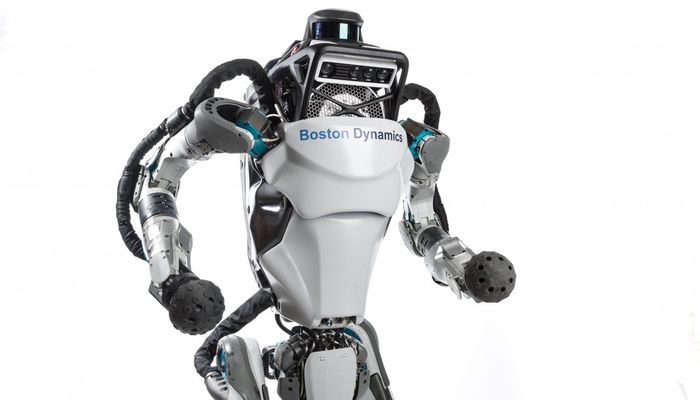
Atlas Robot
The robot is designed to operate both outdoors and inside buildings and has whole-body dynamic balancing. Atlas is able to sense obstacles and negotiate rough terrain autonomously or via teleoperation. The robot is electrically powered and hydraulically actuated. The Atlas hardware takes advantage of 3D printing to save weight and space, resulting in a compact robot with a high strength-to-weight ratio and a large workspace. Stereo vision, range sensing, and other sensors give Atlas the ability to manipulate objects in its environment and to travel on rough terrain. Atlas also keeps its balance when jostled or pushed and can get up if it tips ov
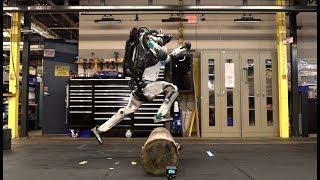
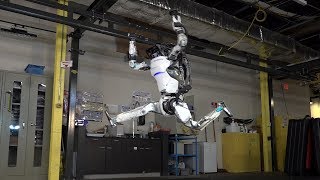
The control software uses the whole body including legs, arms and torso, to marshal the energy and strength for jumping over the log and leaping up the steps without breaking its pace.

Technical Specifications
| Weight | 80 |
| Height | 1.8 |
| Speed | 1.5 |
| Payload | 11 |
| Degrees of freedom (DOF) | 28 |
| Navigation sensors | LIDAR and stereo vision |
| Hydraulic Actuation | Legs |
| Arms | |
| Back | |
| Neck |
Overview
Many humanoid applications can be decomposed into a two stage control problem: a behavior level controller that outputs high level commands and a low level controller that is responsible for generating joint commands. In order to fully utilize the workspace and be robust to external perturbations, the low level controller has to take full body kinematics and dynamics into consideration.
One popular approach to controlling humanoid robots is through inverse kinematics through stiff joint position tracking. On the other hand, inverse dynamics based approaches have gained increasing acceptance by providing compliant motions and robustness to external perturbations. However, the performance of such methods is heavily dependent on high quality dynamic models, which are often very difficult to produce for a physical robot. Inverse Kinematics approaches only require kinematic models, which are much easier to generate in practice.
Control
The proposed full body controller is tested on Boston Dynamics’s Atlas robot in the DARPA Robotics Challenge. Atlas has 28 hydraulic actuators, 6 for each leg and arm, 3 for the back joints, and 1 for neck pitch. Our rough terrain walking, ladder climbing and full body manipulation controllers are all targeted for it.
A. Static Walking
The high level desired motions such as swing foot trajectories are generated with quintic splines. The given foot step locations are used as knot points for the splines.

B. Full body manipulation
During full body manipulation, the operator gives a series of commands requesting either direct joint angles for one or both arms or target Cartesian locations for one or both hands. These commands are used to update the desired position. We use equality constraints in the inverse kinematic formulation to enforce directly-specified joint angles. For large Cartesian motions, we transition the desired locations through splines starting at the current target and ending at the new target. For small motions, we use the “nudge” method as described above for precise foot placement: single keyboard taps result in small instantaneous changes in the desired inverse kinematic position. We then use PD gains comparing the measured and inverse kinematic positions to produce input desired acceleration for the inverse dynamics.
C. Transverse Door Control
Door traversal is generally a trivial task for human beings but particularly challenging for humanoid robots. Door traversal can be broken down into four sub-tasks; door detection, walk to the door, door opening, and walk through the door.
 Transforms and coordinate frames involved in computing the distance. The current end-effector frame is C and the hand pose for grasping
An event driven finite state machine with the sub-tasks as the states is used to control the autonomous execution of the process with human validation at critical junctions. The finite state machine start at the door detection state. Detection is performed using a vision based approach. Once the robot has the normal of the door and the position of the handle a state transition occurs moving the finite state machine to the walking to the door state. At this point the robot follows a stepping trajectory and walks to the desired stand position for opening the door. The third state in the finite state machine is opening the door, which consists of four sub-states. First is moving to the handle. Because of the dimension of the hand and the handle, the error that can be allowed between the desired hand position and the actual position is less than 2 cm. The second sub-state is grasping the handle. When the fingers touch the door, there is still a lot of space between the handle and the palm, which means the hand would generate an unexpected pulling force on the handle after fully grasping the handle. Therefore, the hand needs to move forward around 4 cm when applying grasp motion. Third is opening the door. In this state, our motion planning system is used to generate a sequence of motions, such as turning the handle, pulling out the door for the pull door or pushing away the door for the push door, and raising the arm to prevent the door from reclosing.
C. Ladder climbing
The underlying controller for ladder climbing is similar to that used for manipulation, but the majority of the motion is scripted ahead of time with only the final placement of the hands and feet controlled by the operator. For each limb, the hand or foot is automatically moved to approximately the desired position by placing it relative to the other hand or foot. The correct vertical height is found automatically, using force sensors to detect contact for the feet and position sensing when contact is known to have already occurred. Having all of the weight on the toes makes the robot vulnerable to rotational slipping, causing unexpected yaw rotations. In order to correctly place the hands on the next rung to recover from such rotations, we must rotate the inverse kinematic solution to match the measured orientation. We therefore periodically rotate the inverse kinematic solution such that the feet are aligned with the measured feet orientations, allowing the robot to reorient its upper body towards the ladder and correctly reach targets in the real world. It would have been preferable to update the orientation continuously, but periodic updates were easier from a software engineering perspective. Additionally, periodic updates are less susceptible to the “chase condition” problem described above.
 These photos show the Atlas robot climbing the top half of the same ladder as used in DRC. The snapshots were taken every 13 seconds. The top row shows repositioning of the hook hands, and the bottom row shows stepping up one tread. Most of the climbing motions are scripted. After each limb’s rough repositioning, the operator can fine adjust its final position with “nudge” commands that are small offsets in Cartesian space.
Abilities
In the 2015 Darpa competition of robotics, Atlas was able to complete all eight tasks as follows:
- Drive a utility vehicle at the site.
- Travel dismounted across rubble.
- Remove debris blocking an entryway.
- Open a door and enter a building.
- Climb an industrial ladder and traverse an industrial walkway.
- Use a tool to break through a concrete panel.
- Locate and close a valve near a leaking pipe.
- Connect a fire hose to a standpipe and turn on a valve.
Discussion
The door traversal task can be executed reliably in a wide range of unstructured environments with the perception and motion planning algorithms described above. In the future, it is planned to speed up the motion planner through reuse of previously generated trajectories as initial guesses. Moreover, since the current motion planner only involves kinematic constraints, the low level controller has to follow the trajectory slowly to avoid dynamic instability. All the leg joint level sensing on the Atlas robot such as positioning, velocity and torque are pretransmission. This hardware design choice alleviates jitter in the low level joint control, but introduces problems for forward kinematics and torque control. Unmeasured stiction greatly degrades performance of torque control. Better state estimation technology is necessary to achieve more accurate position tracking and force control.
References
This work focuses on the control structure of the humanoid and discusses the challenges addressed after subjecting their methods to several tests.
In this paper, the researchers discuss an approach to analyze the sensor information of the surroundings to select places where the foot of a humanoid can be placed.
This research is on the holistic approach for a full-sized humanoid robot to traverse through a door in an outdoor unstructured environment as specified by the requirements of the DARPA Robotics Challenge.
Contains videos and images of the robot. The website also gives more background information about the company behind the project.
Recommended Specs

Continue Reading

Unitree launched its first humanoid robot H1 on August 15. Showcasing six months of hard work, the H1 humanoid stands about 71 inches (1800mm) tall, but only weighs about 100 lbs (47kg) and boasts unmatched power.

2 minutes read

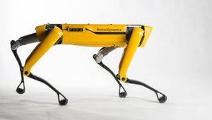
A team of mechanical engineering researchers create “Mugatu,” the first steerable bipedal robot with only one motor.

2 minutes read

Because your robot’s not going to program itself (yet)