Soldering Temperature: Optimizing Heat for Reliable Electronic Assemblies
Achieving the right soldering temperature is crucial for strong, reliable solder joints in electronics. This article explores soldering temperatures – from alloy melting points and heat transfer principles to real-world guidelines for hand soldering and reflow processes

05 Aug, 2025. 18 minutes read
Key Takeaways:
Soldering temperature directly affects joint quality and reliability. Using too low a temperature can lead to weak “cold” solder joints, while too high a temperature risks damaging components or the PCB. Optimal temperature ensures proper wetting and a solid metallurgical bond.
Different solder alloys and processes require different temperature settings. Lead-based solder (Sn-Pb eutectic) melts at 183°C, whereas common lead-free alloys melt around 217°C – thus lead-free soldering typically needs ~30–50°C higher temperature. Hand soldering, wave soldering, and reflow soldering each have recommended temperature ranges and profiles to follow.
Proper soldering temperature balances fast wetting with minimal thermal stress. The soldering iron or reflow oven must be hot enough to melt solder quickly and flow it into joints, but not so hot that flux burns off or components overheat.
Excessively high soldering temperatures cause flux degradation and oxidation. Most electronics fluxes break down above ~350 °C, charring and losing effectiveness. Higher heat also accelerates solder oxidation, which can prevent proper bonding.
Standards and best practices guide engineers on soldering temperatures. Industry guidelines (IPC standards, manufacturer datasheets) provide temperature recommendations for various solders and processes.
Introduction
In electronics manufacturing and prototyping, soldering temperature is a critical parameter that can make the difference between a robust electrical connection and a faulty joint. Soldering involves melting a metal alloy (solder) to join component leads to PCB pads or wires together. The temperature at which this soldering occurs must be carefully controlled: too low, and the solder may not fully melt or bond, leading to weak cold solder joints; too high, and components, printed circuit boards (PCBs), or the solder itself can be damaged (burned pads, charred flux, brittle joints, etc.). Engineers and technicians often ask what the “right” soldering temperature is, but the answer depends on many factors – the solder alloy composition, the soldering method (hand soldering with an iron, wave soldering, reflow oven, etc.), the thermal mass of the assembly, and the sensitivity of components.
This comprehensive guide will delve into both the theoretical concepts and practical implementations of soldering temperature. We’ll discuss:
Why soldering requires temperatures above a solder’s melting point.
Recommended temperature ranges for various soldering techniques – from hand soldering in the lab to automated reflow soldering for PCBs – including real values used in industry.
Possible consequences if temperatures are mismanaged: cold joints, component damage, PCB delamination, etc., and how to prevent these issues.
Best practices for controlling soldering temperature and answer frequently asked questions on the topic.
Understanding Soldering Temperature and Melting Point
Soldering temperature is the temperature at the joint when forming a solder bond. A common misconception is that one should set a soldering iron at the solder’s melting point. In reality, effective soldering requires the joint area to be heated above the alloy’s melting point (liquidus). For example, a typical leaded solder (63% tin, 37% lead eutectic) melts at 183 °C, yet soldering irons are usually set much higher – often around 300–350 °C – to perform good hand soldering.
Similarly, lead-free solders such as SAC305 (Sn-Ag-Cu alloy) melt around 217 °C, but irons and reflow ovens are set tens of degrees higher for successful soldering. Why the disparity? There are several important reasons:
Thermal Transfer and Heat Capacity
When the soldering iron tip touches a joint, it must not only melt the solder but also heat the copper pad and component lead. These act as heat sinks at room temperature. If the iron were exactly at 183 °C, the moment it contacts the cooler workpiece, heat would flow out and the solder could solidify. Thus, the iron needs to be significantly hotter than the solder’s melt point so that it can deliver enough heat into the joint quickly without the temperature dropping below liquidus.
Being well above the melting point ensures a reserve of thermal energy, so the joint area reaches solder liquidus rapidly and stays molten long enough to form a quality bond.
Eutectic vs. Non-eutectic Alloys
Many solders do not transition from solid to liquid at a single temperature but have a plastic (pasty) range between solidus and liquidus. For instance, common 60/40 Sn-Pb solder begins to melt at 183 °C but isn’t fully liquid until about 188 °C, giving it a ~5 °C semi-molten range.
Alloys with less tin (and more lead) have even wider pasty ranges – e.g. a 40/60 solder has a 51 °C pasty span. Within that range, the solder is soft or slushy and doesn’t flow well. Only above the liquidus (the upper end) will the solder freely wet and spread. By using a sufficiently high soldering temperature, we ensure the joint quickly surpasses any pasty stage.
Flux Activation and Effectiveness:
Solder flux is essential for removing oxides and allowing solder to bond to metal surfaces. Fluxes are formulated to activate within certain temperature ranges. If your soldering temperature is too low, the flux may not fully activate to clean the surfaces, or it may not evaporate solvents properly. Conversely, if the temperature overshoots too high, flux can burn. Most electronics fluxes can withstand up to roughly 350 °C; beyond that, they start to decompose and char.
Charred (burnt) flux not only fails to protect the joint from oxidation but can leave residue that insulates or prevents solder wetting. Thus, the soldering temperature must be high enough for the flux to do its job but not so extreme that the flux is spent immediately.
Suggested Reading: A Practical Guide to Solder Flux
Oxidation of Solder and Tip
Hot metals oxidize when exposed to air. The higher the temperature, the faster oxidation occurs. When solder is molten, oxide forms on its surface (the dull film you might see if solder stays liquid too long). Flux combats this by continually cleaning and scavenging oxides – but flux itself gets consumed in the process. At very high tip temperatures, solder and copper pads oxidize almost instantly, and the limited flux is consumed fighting this instead of facilitating wetting.
Additionally, the soldering iron tip itself (usually iron-plated copper) will oxidize faster at elevated temperatures, which is why irons left idling at 400 °C will have blackened, non-wettable tips in short order. Lead-free solder aggravates this because it lacks lead’s anti-oxidation properties – lead-free solder can oxidize tips four to five times faster than eutectic Sn-Pb solder. Thus, from a maintenance perspective, lower tip temperatures extend tip life.
Recommended Reading: Flux Meets Solder: The Chemistry Behind Solder Paste's Role in PCB Assembly
Factors Influencing the Optimal Soldering Temperature
Choosing the proper soldering temperature isn’t one-size-fits-all. Several factors influence what temperature (and time) will yield the best results:
Solder Alloy Composition
Different solder alloys have different melting points. For instance:
Leaded solders (like Sn63/Pb37 or Sn60/Pb40) melt in the ~183–188 °C range,
Lead-free electronics solders (e.g. SAC305: 96.5%Sn/3.0%Ag/0.5%Cu) melt around 217 °C.
Some specialty alloys melt lower (e.g., bismuth-based solders can melt at 138 °C)
Other high-temperature solders with more silver or copper melt at much higher temperatures, i.e., (sometimes 300 °C+).
The general rule is to set the soldering tool about +50–150 °C above the alloy’s melting point, depending on circumstances.
For example, one guideline for hand soldering is “melting point + ~100 °C” as an iron tip temperature. In practice, this means roughly 315–330 °C for lead-free and a bit lower (around 280–300 °C) for tin-lead solder.
Recommended Reading: Types of Solder: A Comprehensive Guide for Engineering Professionals
Soldering Method
The method of soldering greatly affects temperature requirements.
For manual hand soldering with an iron, tip temperatures typically range from about 250 °C up to 350 °C in electronics work.
Reflow soldering uses a temperature profile rather than a single setting – the PCB is gradually preheated, soaked, then brought to a peak temperature just above solder liquidus (for example, ~240 °C peak for Sn-Pb or ~250–260 °C for lead-free), but it’s only at that peak for 30–60 seconds.
Wave soldering (for through-hole components) temperatures are typically fixed around 250–270 °C for tin-lead and ~260–290 °C for lead-free processes.
Selective soldering (spot-applying solder with a mini-wave or solder fountain) will have similar temperatures to wave.
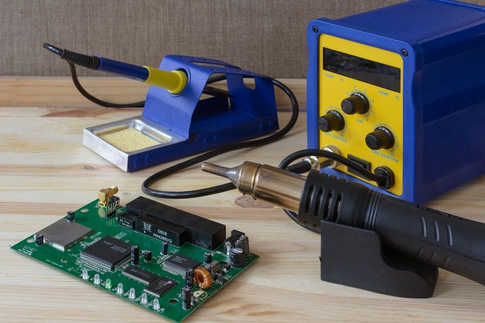
Soldering Irons vs. Hot-air tools
If you’re using hot-air rework tools or soldering stations with different thermal delivery, their temperature settings might differ even if the goal is the same joint temperature (because convection vs. conduction heating have different efficiencies).
Component and Board Thermal Characteristics
The size and thermal mass of what you’re soldering matter. A tiny 0402 resistor will heat up almost instantly, whereas a metal-shielded connector or a multilayer PCB with heavy copper pours will suck heat away aggressively. Thus, soldering a large ground lug might necessitate a higher iron temperature (or the use of preheating) compared to a delicate IC pin. Additionally, some components are sensitive to temperature – for instance, LEDs, some connectors, and plastic headers might deform or get damaged if exposed to excessive soldering heat for too long.
Also, PCB material (FR-4 vs. high-Tg laminates vs. flexible polyimide) can dictate how much heat it can tolerate without delamination or damage.
High-Tg boards can handle reflow peaks of 260 °C for lead-free;
Standard FR-4 can too, but multiple cycles at high temp can stress it.
Boards with metal cores or heavy copper require more heat input but also dissipate heat faster, so sometimes a slower soldering or higher setting is needed.
Recommended Reading: PCB Material: A Comprehensive Guide to Understanding and Choosing the Right Materials
Equipment Capability and Calibration
The performance of the soldering equipment plays a role. A high-power soldering station (say 75–120 W) can often maintain a set temperature under load much better than a small 20 W iron. This means with a powerful station, you might be able to solder a joint at 300 °C that a lower-power iron could only handle by cranking to 350 °C. As a result, professionals with quality equipment often work at lower set temperatures, relying on the iron’s thermal recovery to supply heat on demand.
On the other hand, if the iron’s thermostat is imprecise or uncalibrated, the reading might not reflect actual tip temperature – one station’s “350 °C” could in reality be 320 °C or 380 °C. It’s good practice to calibrate or at least be aware of your specific equipment’s accuracy.
Time and Technique
Temperature cannot be considered in isolation from time. A higher temperature allows a shorter contact time to achieve a good joint, whereas a lower temperature might require holding the iron on the joint longer. Interestingly, an iron set too cold can actually risk overheating components more, because you end up dwelling much longer trying to melt the solder, heat is conducted into the component the whole time.
Recommended Soldering Temperature Ranges for Different Methods
Modern electronics assembly uses several soldering methods, each with its own typical temperature settings or profiles.
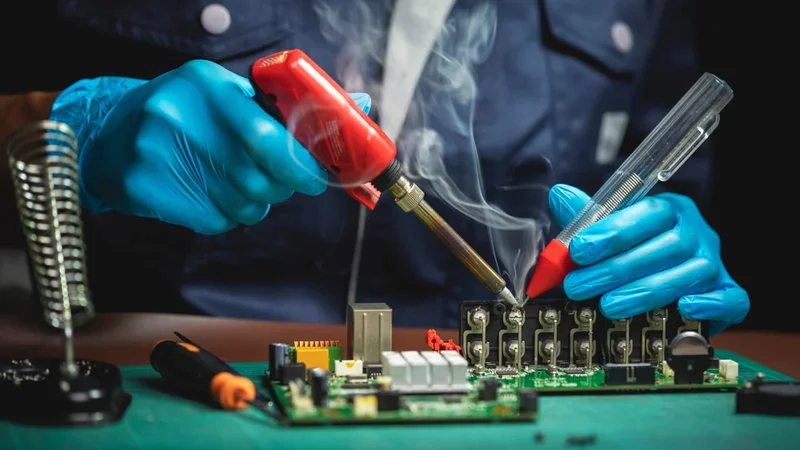
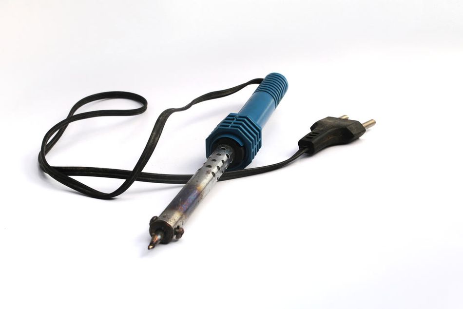
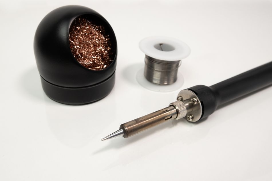
Hand Soldering
For manual soldering with a soldering iron, a good rule of thumb is: set the iron to the lowest temperature that still allows you to form a proper joint in a couple of seconds. In practice, this typically falls in the mid-200s to mid-300s °C:
General-purpose electronics (with tin-lead solder): 300–320 °C is a common range for 60/40 or 63/37 Sn-Pb solder. Because Sn63/Pb37 melts at 183 °C, a 300 °C iron provides plenty of headroom to heat the joint quickly. Many technicians default to around 315 °C (about 600 °F) for everyday leaded solder work. This is significantly above the melting point, but not so high as to immediately burn flux. It allows quick wetting; a typical through-hole joint should take only ~2–5 seconds of contact.
Lead-free solder (SAC alloys): 330–350 °C is a typical setting for hand soldering with lead-free solder. Lead-free solders like SAC305 melt around 217 °C, and they also tend to wet a bit slower than leaded solder. A common recommendation is to go about 100 °C above the melt point, roughly 317 °C, and then add a little more to account for iron tolerances – so 330 °C is a safe choice. Many experienced solderers use ~340 °C on the iron for lead-free to get good flow.
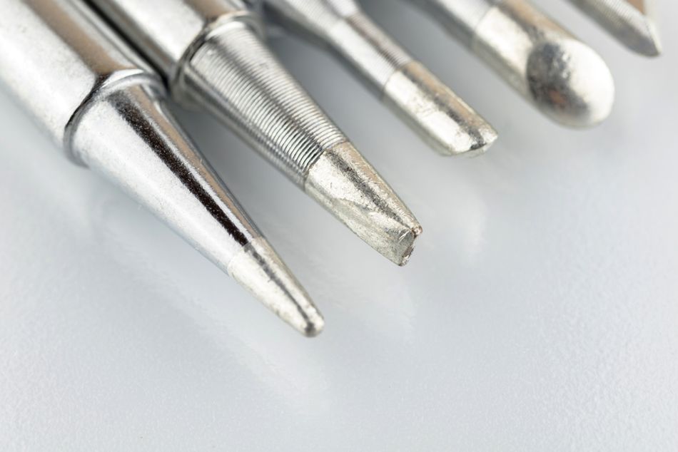
Small SMD work vs. large joints: Smaller work (fine-pitch SMD, small pads) can often be done at the lower end of the range (270–300 °C for leaded, 330 °C for lead-free). Using a fine conical tip may require a bit more temperature or dwell time than a chisel tip due to lower heat capacity, so prefer a larger tip geometry if it can reach the joint – it allows better heat transfer at lower temperatures. For larger joints or thick PCB sections, you might need to bump the iron setting toward the higher end (340–360 °C for lead-free, maybe 320–330 °C for lead).
Maximum safe iron temperature: As noted, flux charring and tip oxidation become serious concerns above 350 °C. It’s advisable not to exceed ~380 °C on your iron for electronics work. Above that, you’re likely scorching the board or pad. Also, many components, plastic connectors, and IC packages start to deform or get damaged if their leads reach those temperatures for more than a moment.
Tip cleaning and maintenance at temperature: When working at elevated iron temperatures, be mindful to frequently clean your tip (using a brass wire sponge or damp sponge) and keep it tinned. The hotter the tip, the faster it oxidizes when not coated in solder. It’s good practice to periodically add a bit of fresh solder to the tip to “re-tin” it during use, especially with lead-free solder, which is harsher on tips. If you pause work, either turn the iron down or feed a blob of solder onto the tip and leave it (to protect it) until you resume.
In summary, for hand soldering, start around 315 °C (leaded) or 330 °C (lead-free) and adjust as needed. Use the lowest temperature that still allows soldering quickly. Many professionals rarely go above 350 °C unless warranted.
Reflow Soldering
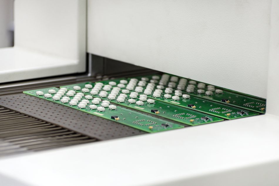
Reflow soldering is the process of soldering surface-mount components by applying solder paste (a mixture of solder powder and flux) and then running the assembly through a controlled heating profile in a reflow oven. Unlike hand soldering, reflow is all about the temperature profile– how the temperature changes over time through different stages.
The goal is to gradually heat the entire board, activate flux, melt the solder, and then cool down at a controlled rate. Here’s an overview of a typical reflow soldering temperature profile and key values (for both tin-lead and lead-free processes):
Preheat Stage: The oven first raises the PCB from ambient (~25 °C) to an intermediate temperature to reduce shock. For tin-lead profiles, preheat might go from room temp up to about 100–150 °C. For lead-free, since final temps are higher, preheat often goes a bit higher, maybe to 150–180 °C. This is done at a moderate ramp rate (e.g. 1–3 °C per second) to avoid thermal stress. Preheating also serves to evaporate solvents in the solder paste and begin activating the flux gently. In practice, many profiles target roughly ~2 minutes to reach around 150 °C.
Soak (thermal equilibrium/flux activation) stage: After initial preheat, the profile often includes a soak period where temperature is held roughly in the range of 150–180 °C for Sn-Pb or 180–220 °C for Pb-free for some tens of seconds. The soak (also called “thermal equalization”) allows the board and components to even out in temperature (so everything is uniformly heated before hitting reflow) and gives flux time to fully activate and clean pads. A typical soak might be 60–120 seconds in that temperature range. This stage ensures that when we ramp to melting, all parts of the board reach solder melt at about the same time, and that solder paste is free of volatiles.
Reflow (time above liquidus) stage: This is the peak heating stage where the solder actually melts and forms joints. For tin-lead (Sn63/37) solder, the peak temperature typically needs to be around 225–240 °C. A common spec is a peak of ~235 °C for a few seconds, with a time above 183 °C (the liquidus) of ~60–90 seconds. For lead-free (e.g. SAC305), because of the higher melting point (~217 °C), the peak is higher – often 245–260 °C. Many manufacturers aim for a peak ~250 °C for SAC, with time above ~220 °C of 60–90 seconds. Industry standards like IPC-JEDEC J-STD-020 specify maximums – often no more than 260 °C peak and no more than ~30 seconds above 255 °C for Pb-free parts.
Cooling stage: After peak, the assembly is cooled down in a controlled manner. Cooling is important to solidify the solder joints and also to relieve stress. If cooling is too slow, solder might form large grains or even stay too long above its solidification point, potentially causing dull joints; if too fast, it could shock components or cause warping. A common cooling rate is on the order of 3–6 °C per second max. Many profiles aim to mirror the heating curve in reverse. Cooling from 260 °C down to ~50 °C might take on the order of 3 minutes. In modern ovens, a fan or cool zone helps bring the temp down. Proper cooling ensures a shiny joint structure and prevents issues like thermal shock to components or PCB (e.g. glass capacitors can crack if cooled too abruptly, and boards can warp).
For clarity, here’s a quick comparison of typical peak temperatures in reflow: Sn-Pb reflow peak ~225–240 °C, Pb-free reflow peak ~245–260 °C.
It’s worth noting that in an SMT assembly line, the oven profile is often fine-tuned to the specific solder paste being used. Paste manufacturers will provide an ideal profile (with temperatures and durations for each zone).
Further Reading: Solder Reflow: An In-Depth Guide to the Process and Techniques
Wave Soldering
Wave soldering is a process primarily used for soldering through-hole components by moving the PCB over a standing wave of molten solder. The solder “wave” is typically a bath of liquid solder pumped to create a flowing wave. Key temperature considerations for wave soldering include:
Solder bath temperature: The pot of molten solder is maintained at a constant temperature. For traditional tin-lead solder, the wave is often held around 250 °C (give or take a few degrees). For lead-free solder, the bath is hotter, around 260–270 °C. Many lead-free wave processes use around 265–270 °C as a happy medium to get good hole fill. Some references cite the wave solder temperature for lead-free at about 280 °C maximum.
Preheat before wave: Unlike hand soldering, wave soldering a PCB requires preheating the entire board before it hits the solder wave. Preheat zones heat the board to around 100–140 °C, typically. The exact preheat temp and duration depend on board size and flux. The goals are to activate the flux and to reduce the thermal shock when the board contacts the ~250 °C solder. If a board went from 25 °C straight into 260 °C solder, components could crack or the board could warp severely. So, preheating might bring it to ~110 °C over a minute or two, then the board encounters the wave and only has to jump another ~150 °C.
Contact time and cooling: The PCB usually passes over the wave in a few seconds (often 3–5 seconds of contact). During that brief window, the solder has to wick up through all the holes and make fillets. The conveyor angle and speed are tuned to achieve this. After the wave, the solder solidifies as the board cools. Cooling is typically ambient or forced air. Proper cooling avoids issues like micro-cracking of joints. The joints from the wave might appear a bit duller if lead-free (as SAC solders naturally give a matte finish), but they should be smooth and fully wetted on both sides of the board.
Summary of Temperature Ranges
To recap the recommended temperature ranges for different methods (assuming standard alloys):
<div><table><tbody><tr><td><strong>Soldering Method</strong></td><td><strong>Solder Type</strong></td><td><strong>Process Stage</strong></td><td><strong>Recommended Temperature Range</strong></td></tr><tr><td><p>Hand Soldering</p></td><td><p>Leaded (Sn-Pb)</p></td><td><p>Small Joints</p></td><td><p>~240–280 °C</p></td></tr><tr><td><p>Reflow Soldering</p></td><td><p>Both</p></td><td><p>Preheat</p></td><td><p>~100–150 °C</p></td></tr><tr><td><p>Wave Soldering</p></td><td><p>Leaded (Sn-Pb)</p></td><td><p>Solder Pot</p></td><td><p>~250 °C</p></td></tr></tbody></table></div>
The key takeaway is to know your process and alloy, and apply an appropriate temperature profile that safely and effectively solder the joints without overshooting and causing damage.
Suggested Reading: Demystifying Soldering Techniques: A Comparison of Wave Soldering and Reflow Soldering
Consequences of Improper Soldering Temperature
Working with solder requires precision, especially regarding temperature. Deviations from the optimal range, whether too low or too high, compromise electronic assembly reliability.
Too Low Temperature / Insufficient Heat
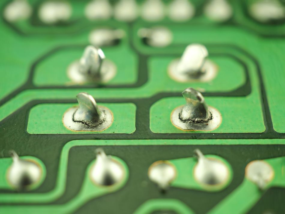
Insufficient heat prevents solder from reaching its proper melting point, leading to poor wetting and weak joints. The most common outcome is a cold solder joint, characterized by a dull, lumpy, or grainy appearance. This occurs when solder doesn't fully melt or flow, often due to an inadequately hot iron or premature heat removal.
While a cold joint might initially show electrical continuity, it's unreliable and exhibits high resistance. Visually, it lacks the smooth, shiny, concave appearance of a proper joint, instead looking like a blob or having a crystalline, rough surface. Intermittent connections are a significant risk.
Low temperatures also hinder flux activation, preventing effective cleaning of oxides and proper solder bonding. Solder may ball up and fail to adhere. In through-hole applications, insufficient heat can prevent solder from filling the hole completely.
Too High Temperature / Excessive Heat
Excessive heat, whether from an iron or reflow process, can cause irreversible damage to components, PCBs, and degrade solder joint quality.
Component Damage: Many electronic components, especially ICs, transistors, and LEDs, are susceptible to heat damage. Overheating can lead to internal bond wire lifting, die damage, melted plastic in connectors, or reduced lifespan and color shifts in LEDs. Exceeding manufacturers' specified maximum soldering temperatures (e.g., "260°C for 10s") can void warranties and compromise reliability.
PCB Damage: The epoxy-fiberglass material of PCBs (FR-4) can char or delaminate, visible as browning around solder joints. Pads or traces can lift if the adhesive holding copper to fiberglass overheats. Repeated or aggressive heating can cause warping, internal layer cracks, and solder mask discoloration or blistering.
Burnt Flux and Solder Joint Integrity: Excessive heat can burn away flux prematurely, leading to oxidation and poor solder adhesion, even if the joint appears visually acceptable. Drastically overheating solder, especially lead-free, can result in a grainy or dull joint structure and leach copper from pads, causing thinning.
Solder Bridges and Splatter: Overly hot and liquid solder is prone to forming unwanted bridges or splattering due to violent flux boiling, a common issue in improperly profiled reflow.
Shortened Equipment Life: Consistently running soldering equipment at maximum temperatures shortens the lifespan of iron tips (due to rapid oxidation) and heater elements. In reflow ovens, higher temperatures can reduce the life of conveyor belts and increase maintenance.
Maintaining soldering temperatures within recommended limits is crucial for strong, reliable joints and avoids costly failures, from intermittent device operation to expensive scrap in manufacturing.
Suggested Reading: Solderability Test - Principles, Methods, and Applications in Electronics Manufacturing
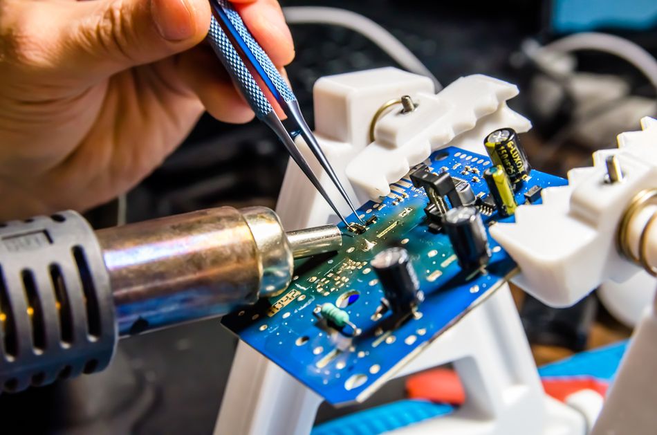
Best Practices for Temperature Control in Soldering
Achieving perfect solder joints requires meticulous temperature management. Here are the key best practices:
Temperature-Controlled Soldering Station
Use a quality station with adjustable temperature and good thermal recovery. This ensures consistent heat delivery, preventing drops during soldering and maintaining the set temperature. Calibrate it with a tip thermometer for accuracy.
Select the Right Tip and Tool
Match tip size to the joint; larger tips (more thermal mass) at moderate temperatures are better for large joints. Avoid compensating for small tips by increasing the heat. For fine work, use specialized tips that concentrate heat efficiently.
Preheat When Necessary
For large ground planes or thick multi-layer boards, preheating the PCB to ~100°C significantly reduces the thermal delta. This allows lower iron temperatures, is gentler on components, and prevents thermal shock during rework of large packages.
Adhere to Thermal Profiles in Reflow
Regularly verify reflow oven profiles with thermocouples on a test board. Adjust settings to match solder paste recommendations, focusing on peak temperature and time above liquidus. Avoid speeding throughput by exceeding specified temperatures.
Work in a Draft-Free Environment
A controlled environment, free from cold drafts, ensures consistent joint cooling. Allow cold PCBs to acclimate to room temperature to prevent excessive thermal shock during soldering.
Flux is Your Friend
Sufficient flux aggressively removes oxides, allowing solder to flow well at lower temperatures. If struggling with wetting, add flux before increasing heat. Clean corrosive flux residues if necessary.
Don't Exceed Component Specs
Be mindful of sensitive components' maximum soldering temperatures and dwell times. For delicate parts, consider swift soldering or using lower-melting solder alloys for rework, understanding potential reliability trade-offs.
Allow for Cooling Between Joints
When soldering multiple pins on a device, pause to allow the component to cool. This prevents heat accumulation and overheating of the entire package, especially for plastic-bodied parts like connectors.
Use Thermometers or Indicators
Validate temperatures with tools like temperature labels or thermocouple devices. Periodically verify iron calibration with a tip thermometer to confirm actual pad temperatures are within range.
Follow IPC Guidelines and Training
Adhere to industry standards like IPC J-STD-001 and IPC-7711/7721. These guidelines provide recommended practices for soldering and rework, emphasizing proper temperature control and tool usage for professional work.
Suggested Reading: IPC Standards: The Definitive Guide for Electronics Engineers and PCB Designers
Conclusion
Mastering soldering temperature is crucial for quality electronic assemblies. First, know your solder alloy and process; lead-free solders and different methods (hand, reflow, wave) demand specific temperature ranges, typically 50-150°C above the melting point.
Second, balance is key: too little heat causes weak, cold joints; too much damages components and PCBs. Prioritize good heat transfer (larger tips, preheating, flux) over simply increasing temperature. Modern electronics require gentle, effective soldering.
Third, process control and training are vital. Adhere to guidelines and monitor processes. Designers also benefit from understanding thermal considerations. The fundamental principles of thermal control remain constant, even as new solder materials emerge. Ultimately, getting the temperature "just right" ensures strong, reliable joints.
FAQs
1. What temperature should I set my soldering iron to for typical electronics work?
For leaded solder, start around 300–320°C; for lead-free, 330–350°C. Adjust for component size: lower for small parts, higher for large connections. Solder should melt and wet in ~2 seconds. Adjust as needed; too hot causes burning, too cold leads to poor flow.
2. Why not just use the lowest possible temperature to be safe?
Too low a temperature prolongs contact time, potentially causing more component stress and cold joints. The goal is rapid, effective soldering. Use the lowest temperature that solders the joint efficiently within 2-5 seconds. If it takes longer, increase the heat slightly.
3. Does lead-free solder really require a hotter iron or oven?
Yes, generally 20-40°C hotter due to a higher melting point and slower wetting. Hand soldering: 330-350°C for lead-free vs. 300-320°C for leaded. Reflow peaks are also higher. This ensures proper flow, but requires components adapted for higher temperatures.
4. What are some signs that my soldering temperature is too high?
Rapid flux burn-off, dull/grainy solder, PCB discoloration/scorching, melting components/plastic smell, frequent tip oxidation, or lifted pads. Ideally, a good joint is shiny (or matte for lead-free) with no board damage.
5. How can I solder a large ground plane or heatsink tab without overheating everything?
Preheat the board to 100-150°C. Use a larger, high-power iron tip for efficient heat transfer. Add extra flux. Work swiftly. For through-hole, solder from both sides. A high iron setting may still be needed, but preheating helps immensely.
6. My solder joints are dull and grainy. Is that caused by wrong temperature?
Yes, it can be. Overheating or movement during cooling can cause dullness/graininess (common with lead-free). Insufficient heat (cold joints) also results in dull, lumpy appearances. Adjust temperature and dwell time to find the "Goldilocks zone" for optimal joint reliability and appearance.
7. What’s the best way to measure or ensure the right reflow profile on my PCB assembly?
Perform thermal profiling: attach thermocouples to a sample PCB and run it through the oven. A data logger records temperature over time. Analyze curves against desired profiles (solder paste datasheet, IPC specs) and adjust oven settings. Essential for consistent quality in production.
References
Solder Melting Temperatures - SimplyMac. [Online]. Available: https://www.simplymac.com/tech/solder-melting-temperatures/.
Andwinpcb, "The Best Temperature to Solder Electronics: A Comprehensive Guide," Andwinpcb. [Online]. Available: https://www.andwinpcb.com/the-best-temperature-to-solder-electronics-a-comprehensive-guide/.
ElectronicsHub, "Reflow Soldering: The Complete Guide & Techniques," ElectronicsHub. [Online]. Available: https://www.electronicshub.org/reflow-soldering/.
FinePowerTools, "Wave Soldering," FinePowerTools. [Online]. Available: https://www.finepowertools.com/soldering/wave-soldering/.
ATETool, "Mastering the Art of Temperature-Controlled Soldering: A Comprehensive Guide," ATETool. [Online]. Available: https://www.atetool.com/news/Mastering-the-Art-of-Temperature-Controlled-Soldering:-A-Comprehensive-Guide.html.
Seeed Studio, "13 Common PCB Soldering Problems to Avoid - Latest News from Seeed Studio," Seeed Studio. [Online]. Available: https://www.seeedstudio.com/blog/2021/06/18/13-common-pcb-soldering-problems-to-avoid/.
in this article
1. Introduction2. Understanding Soldering Temperature and Melting Point3. Factors Influencing the Optimal Soldering Temperature4. Recommended Soldering Temperature Ranges for Different Methods5. Consequences of Improper Soldering Temperature6. Best Practices for Temperature Control in Soldering7. Conclusion8. FAQs9. References