How to Produce a Jet Engine Blade via Automated Fiber Placement (AFP)?
An air-breathing jet engine (turbofan) is widely used in aircraft propulsion. AFP systems are used for making the fan blades and containment casing for these jet engines. Here step by step process of making a jet engine blade via the AFP process is explained.
16 May, 2022. 4 minutes read
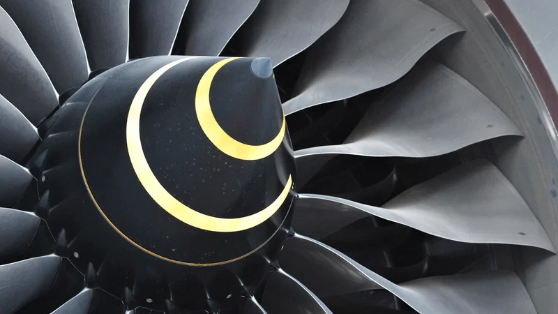
Jet Engine Blades
What is a Jet Engine?
A turbofan is a type of air-breathing jet engine that is widely used in aircraft propulsion. A turbofan engine is the most modern variation of the basic gas turbine engine. As with other gas turbines, there is a core engine, but in the turbofan engine, the core engine is surrounded by a fan in the front which sucks in air, and additional turbine(s) at the rear for exhaust. Most of the air flows around the outside of the engine, making it quieter and giving more thrust at low speeds. Most of today's airliners are powered by turbofans. Such engines have many components and we will focus on the components that are made using continuous fiber composites.
Which are the components made with AFP today?
A leader in the jet engines, Rolls-Royce has recently set up a facility to make fan blades and containment casings using the automated fiber placement process. They used AFP systems to make the fan blades and containment casing respectively.
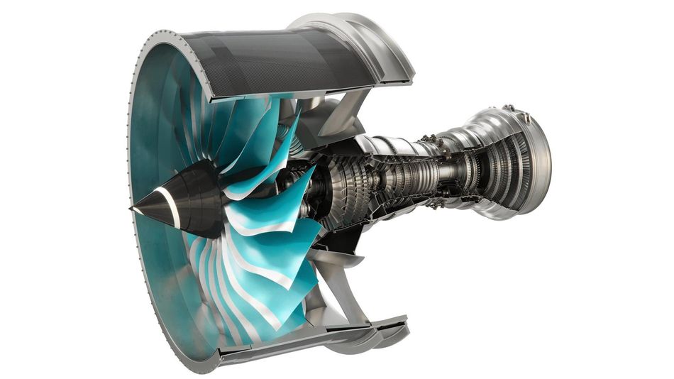
UltraFan, which the company says will be the world’s largest aero-engine and will contribute to sustainable air travel, features what will be the world’s largest fan rotor blades made from carbon fiber-reinforced polymer (CFRP). Here is a video showing glimpses of the overall manufacturing process:
Rolls-Royce's new composite technology hub in Filton (Source: Bristol 24/7)
How to program the blade layup via AFP?
To produce a known geometry using AFP, a few sequential steps must be followed:
Mold model
Planning and programming with AFP
Running AFP manufacturing simulation
Mold modeling
A demo blade model can be downloaded from here or your CAD model of the blade can be used as well. To make the fan blade mold, the following steps are followed:
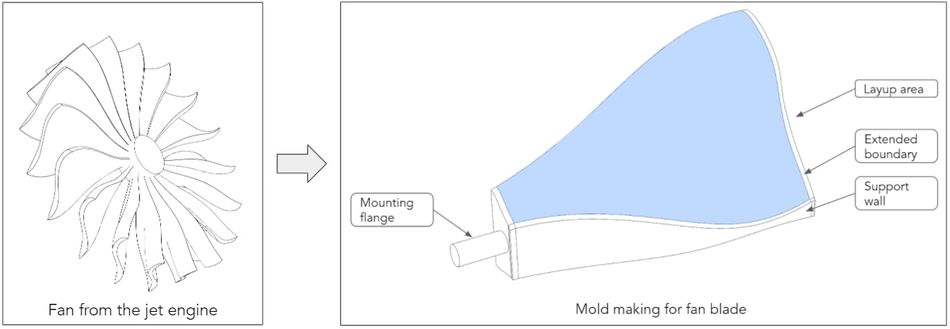
Mold making steps from a fan of the jet engine to mold design
Remove any holes from the fan blade surface
Extend the edges of the surface by up to 50-100 mm, up to 150mm if possible
Plan for the trimming allowance and draw an outer boundary
Separate the layup and the boundary area by splitting the surface
Solidify the surface with vertical walls
Add mounting and alignment points for placement in AFP robotic cell
Consider markings or orientation points for fiber orientation definition
Planning and Programing with AFP
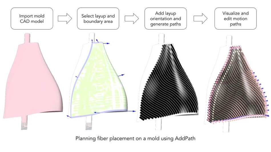
Planning the layup on a 3D mold shape has been made very simple and accessible thanks to AddPath. You can download the AddPath software for free here. A step-by-step process of planning via AddPath is depicted in the picture below. The process also allows user to define their paths by simply drawing a curve in the chosen CAD modeling software and importing it.
Running AFP manufacturing simulation
Simulating the process via 3D Programming Software - AddPath is very critical to make sure the following items are being met without error:
Mold is positioned correctly
The robot can reach the entire layup area without overextending or reaching a point of singularity
Motion sync between robot and mold is smooth and without error
No collisions are occurring
Fiber is being placed where you designed them to be among others...
AddPath allows for modification of mold position to optimize the planned layup placement, thus enabling the part to be optimally designed. Below is the video showcasing the simulation in the finalized position.
Recommended reading: What is Automated Fiber Placement (AFP) in Composites Manufacturing?
Setup your production facility
Setting up your facility for such production used to be very difficult as it would cost millions of dollars and would require the hiring of experts. With the advent of free-to-access software like AddPath, everyone interested in digitally producing composites can join the movement. This virtual production environment provides very critical data for the end-user i.e. material, time, steering/gaps, overlap, feasibility, BOM cost, etc.
As a user feels confident in their business case, they can lease the AFP systems to run onto any available robotic arms (e.g., KUKA, ABB, Fanuc, etc.). The lease prices are equivalent to hiring a skilled technician.
For more information and knowledge about composites manufacturing, you can find it on our website and on the “Blogs” page. If you have further questions, please contact us directly and we are happy to support you.