GD&T Explained: Symbols, Datums, and Tolerances
GD&T is the symbolic language engineers use to state exactly how much a part can vary and still work. This guide covers the basics.

09 Sep, 2026. 11 minutes read
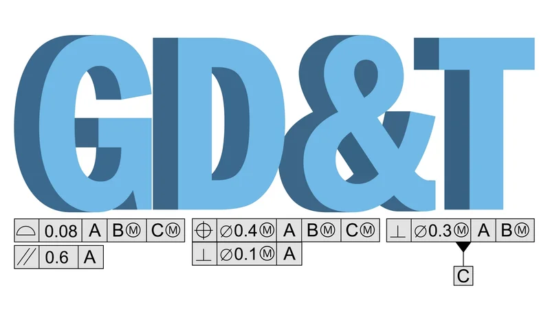
GD&T uses tolerance zones tied to a datum reference frame
Key Takeaways
GD&T (geometric dimensioning and tolerancing) replaces ambiguous plus/minus coordinate dimensions with tolerance zones tied to a datum reference frame, so design intent passes clearly to manufacturing, then to inspection.
ASME Y14.5-2018 (R2024) is the current US standard. It removed concentricity and symmetry, leaving 12 active geometric characteristic symbols rather than the 14 that most references still list.
A cylindrical tolerance zone gives roughly 57% more usable area than the square zone produced by equivalent plus/minus coordinate tolerancing, which is why position callouts use a diameter symbol.
Material condition modifiers (MMC, LMC, RFS) decide whether a feature earns bonus tolerance as it departs from its worst-case material size.
Introduction
Every manufactured part is wrong. The question is whether it is wrong in a way that still assembles and functions. GD&T is the notation that answers that question, and it is the reason a drawing produced in one country can be machined in a second and inspected in a third.
Coordinate tolerancing can state that a hole should sit 25 mm from an edge, plus or minus 0.13 mm. But it does not say which edge governs, what happens if that edge is not flat, or how the part should be held during measurement. Because of these ambiguities, two inspectors can measure the same part against the same drawing and disagree about whether it passes.
Geometric tolerancing removes that ambiguity. It defines a tolerance zone of a specific shape, anchors it to a datum reference frame, and states the rules for evaluating conformance.
This guide works through the GD&T system in logical order: the standards, the feature control frame, the symbols, datums, modifiers, and the arithmetic that inspection departments run.
What Is GD&T?
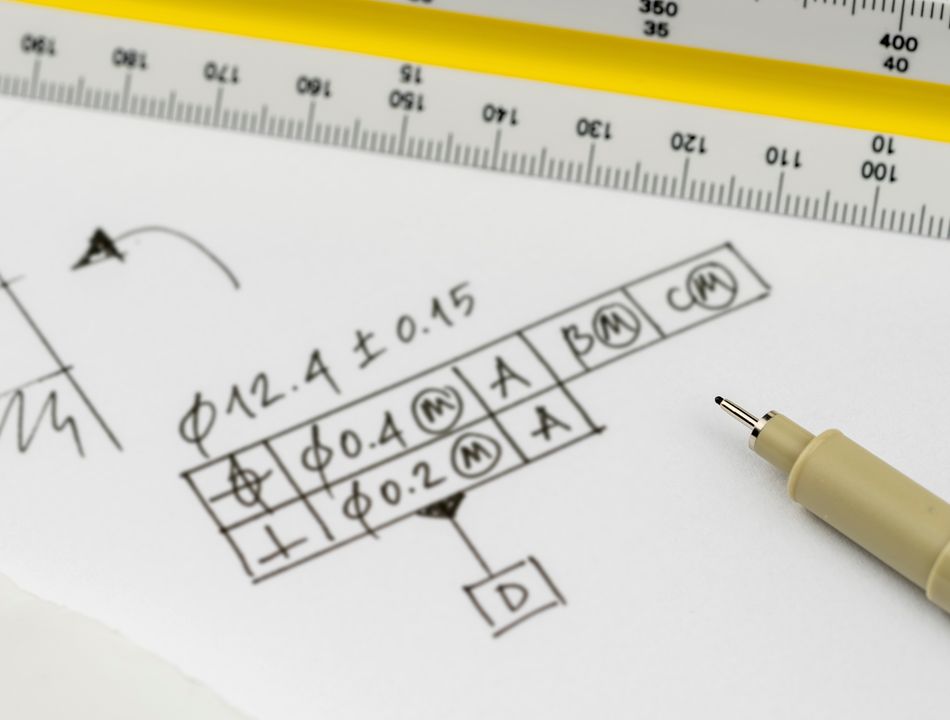
GD&T is a symbolic language for technical drawings and 3D CAD models that specifies permissible variation in part geometry. The ASME Y14.5 standard establishes the symbols, rules, definitions, requirements, defaults, and recommended practices for stating and interpreting these geometric tolerances.[1]
Stanley Parker developed the core ideas at the Royal Torpedo Factory in Scotland, publishing Notes on Design and Inspection of Mass Production Engineering Work in 1940 after proving that his system was more reliable and cost-effective than coordinate tolerances.[2]
There are clear reasons for choosing geometric tolerancing over coordinate tolerancing. Consider a hole located by basic dimensions with plus or minus 0.13 mm allowed in both X and Y.
That creates a square tolerance zone measuring 0.26 mm on each side, with an area of 0.0676 mm². But the functional requirement is radial: the hole needs to accept a fastener regardless of the direction of the error. A point in the corner of that square sits 0.184 mm from nominal, while a point on the flat sits only 0.13 mm away.
Replacing that square with the smallest cylindrical tolerance zone that contains it gives about 57% more usable tolerance for the same functional outcome.[3] This converts directly into looser machining requirements, higher yield, and lower cost for the same function.
GD&T Standards: ASME Y14.5 vs ISO GPS
Two standards systems govern geometric tolerancing. Small differences between them affect how an engineer reads a technical drawing.
Aspect | ASME Y14.5-2018 (R2024) | ISO 1101:2017 |
Publisher | ASME (United States) | ISO/TC 213 (international) |
Structure | Single comprehensive document | One of many linked GPS standards |
Size and form default | Rule #1, envelope principle | Independency principle (ISO 8015) |
Active symbols | 12 | 14, including concentricity and symmetry |
Current status | Stabilized maintenance | Confirmed 2022, remains current |
ISO 1101:2017 is the fourth edition, published February 2017, running 145 pages under technical committee ISO/TC 213. It “defines the symbol language for geometrical specification of workpieces and the rules for its interpretation” and provides the foundation for geometrical specification. It was last reviewed and confirmed in 2022.[4]
ASME Y14.5-2018 has been placed on stabilized maintenance, meaning the edition remains in effect while change requests continue to be considered.[1]
There is one notable difference between the standards. Under ASME Rule #1, also called the envelope principle, the size limits of a feature of size also control its form. A shaft at maximum material condition must have perfect form.[1]
This isn’t the case with the ISO standard. Under the independency principle of ISO 8015, each dimensional and geometric tolerance is met independently unless the drawing states a relationship.[5] To get the same form control on an ISO drawing you must call out a requirement like cylindricity explicitly, or invoke the envelope requirement through ISO 14405.
An engineer who assumes ASME behaviour while reading an ISO drawing will believe form is controlled when it is not.
Recommended reading: ISO 2768 General Tolerances: Tables, Classes, Current Status
Anatomy of the Feature Control Frame
The feature control frame (FCF) is the sentence of this symbolic language. Every geometric tolerance is stated in one, and reading it left to right gives you the complete requirement.
A frame is divided into compartments in a fixed order:
Geometric characteristic symbol: Which of the controls applies: flatness, perpendicularity, position, and so on.
Diameter symbol: A Ø indicates the tolerance zone is cylindrical rather than two parallel planes. Its presence or absence changes the zone shape.
Tolerance value: The width or diameter of the tolerance zone, in drawing units.
Material condition modifier: Optional. MMC, LMC, projected tolerance zone, or unequally disposed profile.
Primary datum reference: The datum feature that constrains the part first.
Secondary datum reference: Constrains remaining rotation and translation.
Tertiary datum reference: Constrains the final degree of freedom.
⌖ | Ø0.5 Ⓜ | A | B | C |
Read as a sentence, a position callout of Ø0.5 at MMC referencing datums A, B, and C says: the axis of this feature must lie within a cylindrical tolerance zone 0.5 mm in diameter, located by basic dimensions from the datum reference frame established by A, then B, then C, and that zone may grow as the feature departs from its maximum material condition.
Datum order is important, as the sequence states which surface the part sits on first during inspection, which is a manufacturing and functional decision.
GD&T Symbols
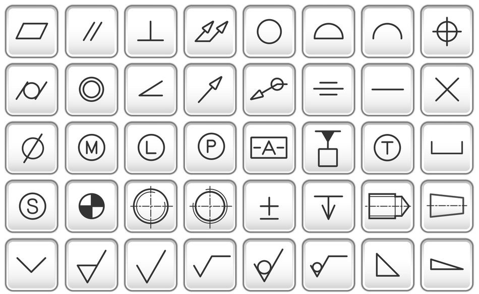
Geometric tolerances fall into five categories. Form controls stand alone, while orientation tolerances such as angularity, perpendicularity, and parallelism always reference at least one datum. The table below reflects ASME Y14.5-2018.[1]
Property | Category | Symbol | What it controls |
Straightness | Form | ⏤ | Deviation of a line element or derived median line from a straight line |
Flatness | Form | ⏥ | Deviation of a surface from a single plane |
Circularity (roundness) | Form | ○ | Deviation of a cross section from a perfect circle |
Cylindricity | Form | ⌭ | Combined circularity, straightness and taper of a cylindrical surface |
Profile of a line | Profile | ⌒ | Cross-sectional deviation from a true profile |
Profile of a surface | Profile | ⌓ | Three-dimensional deviation from a true surface, can control size, form, orientation and location |
Angularity | Orientation | ∠ | Feature at a specified angle to a datum |
Perpendicularity | Orientation | ⟂ | Feature at 90 degrees to a datum |
Parallelism | Orientation | ∥ | Feature parallel to a datum |
Position | Location | ⌖ | Location of a feature axis, centre plane or surface from basic dimensions |
Circular runout | Runout | ↗ | Variation of individual cross sections when rotated about a datum axis |
Total runout | Runout | ⌰ | Variation of an entire surface when rotated about a datum axis |
Older references list 14 geometric characteristic symbols and include concentricity and symmetry under location controls, but Y14.5-2018 withdrew both.[6]
Concentricity and symmetry controlled the location of derived median points, which is expensive to verify on the shop floor. Establishing conformance required collecting extensive point data across the feature and computing median points, a burden that rarely matched the functional requirement.[6]
Coaxiality is now handled by position applied regardless of feature size, which controls the axis of the actual mating envelope, or by profile of a surface, which controls the surface elements directly. Symmetrical relationships take position or profile applied to the derived median plane.
Concentricity and symmetry still appear on legacy drawings and on ISO drawings, so you need to be able to read them, though you should not specify them on new ASME work.
The 2018 edition also introduced the dynamic profile modifier, which controls form separately from size and lets you tighten shape without tightening the size tolerance. Furthermore, it clarified the continuous feature symbol for continuous surfaces, and confirmed that a profile all over modifier can be placed in the title block to apply a tolerance across an entire 3D shape.[6]
Datums and the Datum Reference Frame
A datum reference frame (DRF) is the reference coordinate system used in GD&T to define how a part is oriented and inspected. It is established from datum features, which are real physical surfaces or features on the part, and their corresponding theoretical datums, which are simulated by inspection equipment.[7]
The order of the datums is important because each one progressively restricts the part’s degrees of freedom, ideally locking all six. When possible, datums should be selected in the same order that the part would assemble in practice.[7]
When selecting datums, pick surfaces that:
Mate with the assembly, so the drawing reflects how the part is actually located in service.
Are accessible and stable for fixturing during machining and inspection.
Are large enough to establish a repeatable datum plane or axis. A small pad makes a poor primary datum because minor surface variation swings the whole DRF.
A common and costly error is selecting datums for inspection convenience rather than function. The part then passes inspection and fails at assembly, because the drawing constrained the wrong relationship.
Material Condition Modifiers and Bonus Tolerance
Material condition modifiers connect a geometric tolerance to the actual size of the feature. They generate bonus tolerance, which in turn lowers scrap rates.
Modifier | Symbol | Meaning | Bonus tolerance |
Maximum material condition (MMC) | Ⓜ | Feature contains the most material: smallest hole, largest shaft | Yes |
Least material condition (LMC) | Ⓛ | Feature contains the least material: largest hole, smallest shaft | Yes |
Regardless of feature size (RFS) | None, this is the default | Tolerance applies at any actual size | No |
- Use MMC when the concern is assembly clearance.
- Use LMC when the concern is retaining material, such as minimum wall thickness around a hole or minimum engagement.
- Use RFS when the tolerance must hold at every size, as in precision alignment features and bearing seats.
When a feature departs from its stated material condition, the difference becomes additional geometric tolerance. But bonus tolerance is technically based on the feature’s true envelope size, not just its actual size. The two only match when the feature has perfect form.
By the logic of bonus tolerance, a larger hole has more clearance around the fastener, so it can sit further from nominal and still assemble. MMC lets the drawing grant that tolerance rather than waste it.[8]
Virtual condition
Virtual condition is the worst-case boundary a feature can occupy, combining size and geometric tolerance:
Internal feature (hole) at MMC: VC = MMC size - geometric tolerance
External feature (shaft) at MMC: VC = MMC size + geometric tolerance
This number is what functional gauges are built to, and therefore helps determine whether a tolerance scheme actually guarantees assembly.
Projected tolerance zone
For threaded holes and press-fit pins, controlling the hole is not enough. What matters is where the fastener ends up once installed, because a slight angular error in the tapped hole is amplified over the length of the protruding stud.
The projected tolerance zone modifier moves the tolerance zone out of the part and into the space the fastener occupies, with the projection height normally set to the maximum thickness of the mating part or the maximum height of the pin or stud.[9]
True Position Calculation
Position is the most-used control in GD&T. The feature’s nominal location comes from basic dimensions, which are theoretically exact and carry no tolerance of their own. All permissible variation is in the feature control frame.
For a feature located in two axes, true position is:
True position = 2 × √(ΔX² + ΔY²)
where ΔX and ΔY are the deviations between measured and nominal coordinates.
The factor of 2 converts a radial deviation into a diametral value, because position tolerances are stated as zone diameters.
Recommended reading: True Position in GD&T: Formula, Tolerance Zones, and MMC
Inspecting GD&T

A geometric tolerance is only as good as the ability to verify it. Coordinate measuring machine (CMM) inspection is the usual method, but optical systems and physical gauges can also be used.
The sequence for CMM inspection goes like this:
Establish the datum reference frame: Measure the datum features in the order stated in the feature control frame and fit the coordinate system to them.
Measure the toleranced feature: Collect enough points to characterise the geometry rather than sample it. Four points on a circle cannot reveal a three-lobed form error.
Fit and evaluate: The software fits the measured data into the tolerance zone under the datum constraints and reports the result.
The fitting algorithm can vary. For example, a default minimum-zone best fit finds the smallest tolerance zone containing the surface points, while a least-squares fit is faster but more conservative. The same measured points can pass under one method and fail under the other.[10]
For profile of a surface, the tolerance zone is equal bilateral by default, with half the tolerance value on each side of the nominal surface. The unequally disposed and dynamic profile modifiers shift or offset that zone.
Exchange and Interpretation
Transferring GD&T between systems can cause issues. A NIST publication by Simon Frechette and Bryan Fischer notes that GD&T is created in CAD and reused downstream for engineering, production, and inspection, but “the complexity of those standards frequently causes both exchange and interpretation errors,” which “can result in significant delays and cost overruns.”[11]
If your workflow depends on model-based definition, you should validate that geometric tolerances survive translation between CAD, CAM, and inspection software rather than assuming they do.
Recommended reading: Tolerance Stack Up Analysis: Worst Case vs RSS Methods
Conclusion
GD&T is helpful because it makes drawings unambiguous. Engineers simply need to define a tolerance zone with a relevant shape, anchor it to a datum reference frame from the most important surfaces, and use material condition modifiers to match the tolerance to the function.
Applied well, geometric tolerancing loosens the tolerances that do not matter and tightens only the ones that do. And this ultimately reduces the cost of both manufacturing and inspection.
Frequently Asked Questions
What does GD&T stand for?
GD&T stands for geometric dimensioning and tolerancing. It is a symbolic language used on engineering drawings and 3D models to define the permissible variation in a part’s geometry, standardised in the United States by ASME Y14.5 and internationally by the ISO GPS standards.
How many GD&T symbols are there?
ASME Y14.5-2018 defines 12 active geometric characteristic symbols. Earlier editions and ISO 1101 include 14, the additional two being concentricity and symmetry, which ASME withdrew in 2018 because they were difficult and expensive to verify.
What is the difference between position and true position?
In practice they refer to the same control. Position is the name of the geometric characteristic symbol in ASME Y14.5. True position is the theoretically exact location, defined by basic dimensions, that the tolerance zone is centred on, and inspection reports also use the term for the calculated deviation value. Drawings use both terms interchangeably.
When should I use MMC instead of RFS?
Use maximum material condition when the requirement is assembly clearance, because it grants bonus tolerance as the feature departs from its worst-case material size and reduces manufacturing cost. Use regardless of feature size when the tolerance must hold at every actual size, such as bearing seats and precision alignment features.
Do form tolerances need a datum?
No. Straightness, flatness, circularity, and cylindricity control a feature against itself and never reference a datum. Orientation, location, and runout controls all require at least one datum reference. Profile controls may reference datums or not, depending on whether they control location as well as form.
What is a basic dimension?
A basic dimension is a theoretically exact value, shown boxed on the drawing, that defines the nominal location or orientation of a feature. It carries no tolerance itself. All permitted variation is stated in the associated feature control frame.
Is GD&T required for CNC machined parts?
Not always. Simple parts with generous fits are adequately defined by plus/minus dimensions. GD&T becomes valuable when parts must assemble interchangeably, when form or orientation matters independently of size, or when coordinate tolerancing would force tighter tolerances than the function requires.
What is the difference between circularity and cylindricity?
Circularity, also called roundness, controls each individual cross section against a perfect circle. Cylindricity controls the entire cylindrical surface at once, capturing circularity, straightness of the axis, and taper together. Cylindricity is the tighter and more expensive requirement.
References
[1] American Society of Mechanical Engineers. Y14.5 dimensioning and tolerancing [Internet]. New York (NY): American Society of Mechanical Engineers; 2019 Feb 11 [cited 2026 Sep 8].
[2] Autodesk. Geometric dimensioning and tolerancing in design and manufacturing [Internet]. San Francisco (CA): Autodesk; [cited 2026 Sep 8].
[3] GD&T Basics. True position: position tolerance [Internet]. Greenville (SC): GD&T Basics; 2014 Dec 22 [cited 2026 Sep 8].
[4] International Organization for Standardization. ISO 1101:2017 Geometrical product specifications (GPS): geometrical tolerancing: tolerances of form, orientation, location and run-out [Internet]. Geneva: International Organization for Standardization; 2017 Feb [cited 2026 Sep 8].
[5] International Organization for Standardization. ISO 8015:2011 Geometrical product specifications (GPS): fundamentals: concepts, principles and rules [Internet]. Geneva: International Organization for Standardization; 2011 Aug [cited 2026 Sep 8].
[6] Afridi S. ASME Y14.5 2009 vs. 2018: standard changes [Internet]. Greenville (SC): GD&T Basics; 2020 Dec 1 [cited 2026 Sep 9].
[7] Bemis C. The datum reference frame [Internet]. Greenville (SC): GD&T Basics; 2022 Apr 4 [cited 2026 Sep 9].
[8] GD&T Basics. Maximum material condition (MMC) [Internet]. Greenville (SC): GD&T Basics; 2014 Dec 13 [cited 2026 Sep 9].
[9] Tec-Ease. Projected tolerance (#5A) [Internet]. Fredonia (NY): Tec-Ease, Inc.; 1997 Oct [added 2019 Nov; cited 2026 Sep 9].
[10] Hexagon Manufacturing Intelligence. Profile of a surface [Internet]. PC-DMIS 2020.2 help center; 2020 Dec 10 [cited 2026 Sep 9].
[11] Frechette SP, Fischer B. A strategy for testing product conformance to geometric dimensioning & tolerancing standards. In: CIRP-CAT Conference 2012; 2012 Apr 18-19; Huddersfield, UK. Gaithersburg (MD): National Institute of Standards and Technology; 2012 [cited 2026 Sep 9].
in this article
1. Introduction2. What Is GD&T?GD&T Standards: ASME Y14.5 vs ISO GPS4. Anatomy of the Feature Control Frame5. GD&T Symbols6. Datums and the Datum Reference Frame7. Material Condition Modifiers and Bonus Tolerance8. True Position Calculation9. Inspecting GD&T10. Conclusion11. Frequently Asked Questions12. References