True Position in GD&T: Formula, Tolerance Zones, and MMC
This guide covers the true position formula, how to read the feature control frame, and how MMC and LMC generate bonus tolerance.

03 Sep, 2026. 13 minutes read
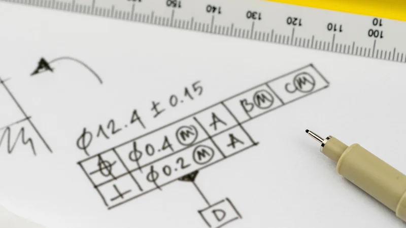
True position is an important concept in GD&T
Key Takeaways
True position uses a diametral tolerance zone centered on the theoretically exact location set by basic dimensions.
The true position formula is TP = 2 × √(Δx² + Δy²). The factor of 2 converts a radial deviation into the diameter of the tolerance zone quoted in the feature control frame.
Applying maximum material condition (MMC) to the tolerance value earns bonus tolerance equal to the departure of the actual mating envelope from MMC, which is why MMC callouts reduce scrap on clearance holes.
ASME Y14.5-2018 removed the concentricity and symmetry symbols, so position now carries work those symbols used to do.
Introduction
Most location problems on an engineering drawing come down to one question: how far can this hole wander before the part stops working? Plus/minus coordinate dimensioning answers that question badly, whereas true position answers it in a way that matches how parts actually assemble. Position is defined in the ASME Y14.5 standard for geometric dimensioning and tolerancing (GD&T).[1]
This article works through the geometry, the arithmetic, the modifiers, and the metrology of true position. It assumes you can read a drawing but not that you have sat a GD&T certification. If you are new to GD&T, the sections on the tolerance zone and the formula are the place to start.
What True Position Means in GD&T
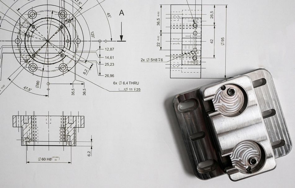
Position (⌖) is a location control. It applies to a feature of size: a hole, a boss, a pin, a slot, a tab, or a sphere. It controls where the derived center axis or center plane of that feature sits relative to a datum reference frame.[2]
Two pieces of information define the control:
The true position itself: This is the theoretically exact location, established by basic dimensions.
The tolerance value: This is the size of the zone around that target inside which the derived feature must lie.
The term “true position” is informal shorthand. The ASME Y14.5 standard uses the term “position.” Engineers say true position because the theoretically exact location is the true position and the true position tolerance is measured from it. In practice the two terms are used interchangeably, and a drawing that says either one means the same control.
Position does not control the form of the feature. A hole can be badly out of round and still pass a position check, because position evaluates the location of the derived axis, not the shape of the wall.
Concentricity and symmetry were removed from ASME Y14.5-2018 because they were complex to verify and were routinely confused with position.[3] If you inherit a legacy drawing with a concentricity callout, position is normally the correct replacement control.
Advantages of a Cylindrical Tolerance Zone
There are simple mathematical reasons for using position over coordinate dimensioning.
Suppose you dimension a hole as X = 40 +/- 0.25 and Y = 25 +/- 0.25. The set of acceptable hole centers is a square tolerance zone 0.5 mm on a side. A hole that is 0.25 mm off in X and 0.25 mm off in Y passes, even though it sits 0.354 mm from where you wanted it. A hole that is 0.30 mm off in X alone fails, even though it is closer to the target.
What matters for assembly is radial distance from the nominal position, and radial distance does not care about direction.
Now take the circle that circumscribes that square. Its diameter is 0.5 × √2 = 0.707 mm. Compare the areas:
Square tolerance zone: 0.5 × 0.5 = 0.25 mm²
Circular tolerance zone of diameter 0.707 mm: π × (0.3535)² = 0.393 mm²
That is 57% more usable tolerance for the same worst-case corner deviation.[2]
The cylindrical tolerance zone extends through the full depth of the feature, so it controls the axis along its whole length, not just where the axis crosses one face. ISO 1101:2017 handles this explicitly in its clause on cylindrical and spherical tolerance zones.[4]
Note that if the tolerance value in the GD&T feature control frame is preceded by the diameter symbol, the zone is a cylinder. If the diameter symbol is absent, the zone is not cylindrical: you get a square tolerance zone or a pair of parallel planes, depending on the callout.[2]
True Position Formula
Inspection equipment measures deviations in X and Y, but the feature control frame states a diameter, so you need to convert between them.
True position formula:
TP = 2 × √(Δx² + Δy²)
where Δx is the measured deviation from the nominal value in X and Δy is the deviation in Y.
The square root term gives the radial distance from the true position. The tolerance value in the feature control frame is a diameter, so you double the radius to get a comparable positional deviation.
Three-dimensional and compound position
For a hole in a flat plate you evaluate deviation in the two axes of the plate face. For features located in three axes, such as a hole in a casting located from three mutually perpendicular datums, extend the formula:
TP = 2 × √(Δx² + Δy² + Δz²)
For a bolt circle you can work in polar coordinates and convert, but converting the nominal and actual positions to Cartesian coordinates first and then applying the standard formula is less error prone.
Should you use a true position calculator?
A true position calculator is useful for a spot check, and the arithmetic above is what every one of them runs. In production you should not be typing numbers into one, because any coordinate measuring machine package evaluates position directly against the feature control frame.
Use a true position calculator when you are reviewing a supplier’s inspection report that lists raw X and Y deviations, when you are estimating during design, or when you are teaching the concept.
Recommended reading: Tolerance Stack Up Analysis: Worst Case vs RSS Methods
Reading the Feature Control Frame
A position callout carries everything in one row of compartments, and it is the densest piece of notation in GD&T:
⌖ | Ø0.25 Ⓜ | A | B | C |
Read the example panel as one sentence: the axis of this feature must lie within a cylindrical tolerance zone of 0.25 mm diameter, positioned at the true position defined by basic dimensions, when the part is constrained in the datum reference frame A, B, C, and the zone may grow as the feature departs from MMC.
Basic dimensions and the datum reference frame
Basic dimensions locate the true position. They are boxed on the drawing, carry no tolerance of their own, and are the only correct way to dimension to a positioned feature. Mixing a toleranced dimension into the location chain of a positioned feature is an error: the tolerance in the feature control frame is then double counted.
ISO uses the term theoretically exact dimension (TED) rather than basic dimension, and ISO 1101:2017 devotes a dedicated clause to them.[4] However, the concept is identical.
The datum reference frame does the other half of the work. Datum features are the physical surfaces on the part. The datums themselves are the derived perfect geometry: a plane, an axis, a point. Listed in order, the datum features constrain degrees of freedom in sequence: the primary datum feature typically removes three, the secondary two, and the tertiary one.
Position to A, B, C and position to B, A, C are different requirements and will give different measured results on the same part, so choose the order that reflects how the part actually seats in the assembly, and probe the datum features where the part contacts its mating fixture rather than in the middle of a convenient surface.
Material Condition Modifiers: MMC, LMC, RFS
The tolerance value in a position callout can be qualified by a material condition modifier. This is the part of GD&T that pays for itself fastest on high volume parts.
Modifier | Symbol | Meaning | Typical use |
MMC | Ⓜ | Tolerance applies at maximum material condition; bonus tolerance available | Clearance holes, fasteners, assembly fits |
LMC | Ⓛ | Tolerance applies at least material condition; bonus tolerance available | Protecting minimum wall thickness or edge distance |
RFS | none | Regardless of feature size; tolerance is fixed at every size | Alignment critical features, press fits, bearing bores |
Under ASME Y14.5, regardless of feature size (RFS) is the default when no modifier is shown. If the feature control frame says Ø0.25 to A, B, C with no modifier, the tolerance is 0.25 mm at every produced size and no bonus tolerance is available.
Bonus tolerance and how to calculate it
When you apply MMC, the position tolerance grows as the feature departs from its maximum material condition. Bonus tolerance is the difference between the MMC size and the size of the unrelated actual mating envelope (UAME).[5]
A clearance hole that comes out larger than its minimum size leaves more room for the fastener, so the hole can sit further from its nominal position and still assemble.
For an external feature such as a pin or boss, MMC is the largest size, and the bonus accrues as the feature gets smaller.
Least material condition
Least material condition (LMC) is the right modifier when the risk is not assembly clearance but material running out: a hole too close to an edge, or a boss with a minimum wall thickness requirement. Under LMC, the bonus accrues as the feature departs from its least material size, which keeps the worst case wall thickness protected.
LMC is far less common than MMC and is not applicable to a functional gauge in the same simple way, because the gauge would have to simulate the least material boundary rather than a solid mating part.
Virtual condition and functional gauge design
MMC callouts allow attribute inspection with a hard gauge, and the gauge size falls straight out of the callout.
For an internal feature such as a hole:
Gauge pin diameter = MMC size of the hole - true position tolerance value[2]
For an external feature such as a pin:
Gauge hole diameter = MMC size of the pin + true position tolerance value[2]
A gauge gives no variation in operation speed or inspection quality, but must be custom fabricated for each application, which is a substantial cost that is hard to justify during prototyping.[6] The gauge also returns pass or fail with no measured value, so it gives you nothing for process control.
Composite Position Tolerance

A pattern of holes often has two different requirements: the pattern as a whole has to land in roughly the right place, and the holes have to be accurate relative to each other. A composite position tolerance states both in one callout, using a single position symbol with two horizontal segments, and functions as an advanced tool for fine-tuning orientation in parts with hole patterns.[7]
The upper segment is the pattern-locating tolerance zone framework (PLTZF). It locates and orients the whole pattern relative to the full datum reference frame.
The lower segment is the feature-relating tolerance zone framework (FRTZF). It controls the relationship of the features to each other, with a tighter tolerance value.
This is the callout to use when a bolt pattern must mate with a connector but the connector’s absolute position on the housing has generous tolerance.
Projected Tolerance Zones
For a threaded hole or a press fit pin that will carry a long fastener, controlling the axis inside the part is not enough, since a small angular error in a 10 mm deep tapped hole becomes a large positional error at the far end of a 40 mm bolt.
A projected tolerance zone moves the cylindrical tolerance zone outside the part, into the space the mating fastener will occupy, and specifies its height. ISO 1101:2017 covers this under projected toleranced features.[4]
Recommended reading: Press Fit Tolerance: How to Specify Interference Fits
How True Position Is Measured

CMM inspection
A coordinate measuring machine is the standard method. The sequence is:
Seat and constrain the part, ideally the way it seats in the assembly.
Probe the datum features in the order listed in the feature control frame and build the datum reference frame from them.
Probe the toleranced feature.
Let the software fit the feature, derive the axis, and compare it with the true position.
The NPL Measurement Good Practice Guide No. 41 is the reference to work from for preventing measurement errors. It reproduces the minimum point counts from BS 7172:1989:[8]
Geometric feature | Mathematical minimum | Recommended minimum |
Straight line | 2 | 5 |
Plane | 3 | 9 (approximately three lines of three) |
Circle | 3 | 7 (to detect up to six lobes) |
Sphere | 4 | 9 |
Cylinder | 5 | 12 (circles in four parallel planes), 15 for roundness information |
Cone | 6 | 12 to 15 |
Cube | 6 | 18 (at least three per face) |
Two points from that guide bear directly on position measurement of holes:
Probe cylindrical features as cylinders, not circles. When a hole’s axis is not square to the datum plane it was machined into, probing all touch points in one plane produces a computed center that does not correspond to where the hole actually intercepts that plane, and the hole reports as elliptical. Probing in several parallel planes lets the software compute where the cylinder axis intersects the plane and also returns the out-of-squareness in XZ and YZ.[8]
Distribute points and alternate the count. For 30 points over four circles, NPL works np = N/nc = 30/4 = 7.5 and recommends 7 or 8 per circle, alternating odd and even counts between circles so that lobing is detected. More circles with fewer points each favors straightness information; fewer circles with more points each favors roundness.[8]
The stylus tip diameter is added when probing a hole and subtracted when probing a shaft. Most software handles this automatically once you declare the feature type, but a misdeclared internal or external feature produces an error of one full stylus diameter.[8]
Temperature
Dimensional metrology is defined at 20 °C, and thermal effects are not negligible at position tolerances in the tens of micrometers. NPL works an example for a 1 m steel bar with a coefficient of thermal expansion of 11.5 × 10⁻⁶ per K, an uncertainty in that coefficient of 0.58 × 10⁻⁶ per K, and a temperature measurement uncertainty of 0.1 K, and shows that even a temperature compensated measurement retains a residual uncertainty from those two terms.[8] Uncompensated measurement is worse by a wide margin.
If your position tolerance is 0.05 mm and your parts arrive on the inspection bench straight off a CNC machining center, soak them before measuring.
Budgeting the tolerance
For a position tolerance with no material condition modifier, everything has to fit inside the stated value: form error of the datum features, perpendicularity of the secondary and tertiary datums, the actual location error of the feature, and the measurement uncertainty of the CMM itself. A 0.03 mm position tolerance with a measurement uncertainty of 0.01 mm has already spent a third of its budget before the part is touched.
Recommended reading: The Comprehensive Guide to CMM Technologies
ASME Y14.5 Against the ISO GPS System
Drawings do not all follow the same standard.The ASME Y14.5 standard is a single, largely self-contained document covering the whole GD&T system in its 2018 edition. The ISO Geometrical Product Specification system splits the same subject matter across many standards, each addressing one topic.
Topic | ASME | ISO |
Core symbols and tolerance zones | Y14.5-2018 | ISO 1101:2017 |
Position patterns and combined specification | Y14.5-2018 | ISO 5458:2018 |
Material condition modifiers | Y14.5-2018 (MMC, LMC) | ISO 2692:2021 (MMR, LMR, RPR) |
ISO 1101:2017 is the fourth edition, prepared by ISO/TC 213, replacing ISO 1101:2012, and was reviewed and confirmed as current in 2022.[4]
ISO 5458 changed meaning. The old ISO 5458:1998 was titled “Positional tolerancing” and has been withdrawn. Its replacement, ISO 5458:2018, is titled “Pattern and combined geometrical specification” and establishes rules complementary to ISO 1101 for patterns, including a specific Rule A for position specification and the CZ, CZR and SIM modifiers.[9] Pattern specification under ISO 5458:2018 does not cover cases where the maximum or least material requirement applies. Those are handled by ISO 2692.[9]
ISO 2692:2021 is the current edition. The 2014 edition has been withdrawn. ISO 2692:2021 defines MMR and LMR, the ISO equivalents of MMC and LMC, and adds the reciprocity requirement (RPR), which has no direct ASME counterpart.[10]
Choosing a Tolerance Value
When choosing a tolerance value, work backwards from the function. For a clearance hole and fastener:
Position tolerance at MMC = hole MMC size - fastener maximum diameter
For a Ø8.00 minimum hole and an M6 fastener at Ø6.00 maximum, the clearance is 2.00 mm, which is the total diametral float available. Split it between the two mating parts if both are toleranced with position, for example Ø1.00 Ⓜ on each.
Then check that the value is producible on the chosen machinery.
Conclusion
The key to applying true position effectively is to think about how the part will actually be made, measured, and assembled. The tolerance zone, material condition, datum scheme, and inspection method all need to work together. When they do, the drawing gives manufacturers more useful freedom while still controlling the features that matter for assembly and function. The ultimate goal is tolerances that reflect how the part needs to perform in the real world.
Frequently Asked Questions
What is the true position formula?
TP = 2 × √(Δx² + Δy²), where Δx and Δy are the deviations of the measured feature center from its nominal position in X and Y. For three axis location, add Δz² inside the square root.
Why is the true position result multiplied by 2?
Because the square root term gives a radius, the distance from the true position to the measured center, while the tolerance value in the feature control frame is stated as a diameter.
What is the difference between position and true position?
Position is the name of the geometric characteristic symbol in ASME Y14.5. True position refers to the theoretically exact location that the tolerance zone is centered on. Drawings and inspection reports use both terms for the same control.
How much bonus tolerance does MMC give?
Bonus tolerance equals the difference between the MMC size and the size of the unrelated actual mating envelope. For a Ø8.00 to Ø8.20 hole at MMC with a produced size of Ø8.12, the bonus is 0.12 mm, which is added to the stated tolerance value.[5]
When should you use RFS instead of MMC?
Use regardless of feature size when the feature sets alignment rather than providing clearance: bearing bores, dowel holes, press fits, and optical or sealing interfaces. Bonus tolerance would let those features drift in a way the function cannot absorb. RFS is the ASME default when no material condition modifier is shown.
Can true position be applied to slots?
Yes. Applied to a slot, position controls the center plane rather than a center axis, and the tolerance zone is a pair of parallel planes rather than a cylinder. The diameter symbol is not used in that case.
Does true position control the shape of the hole?
No. Position evaluates the location of the derived center axis or center plane. Roundness, cylindricity, and straightness of the wall need their own form controls, though a position tolerance applied at MMC does establish a virtual condition boundary that the surface must not violate.
Was concentricity replaced by position?
Effectively, yes. ASME Y14.5-2018 removed concentricity and symmetry because they were difficult to verify and routinely confused with position.[3] On new drawings, position or profile normally expresses the intent those symbols were used for.
How many points should you probe on a hole for a position check?
NPL recommends 12 points in four parallel circles as a minimum, or 15 if you also need roundness information, and advises alternating odd and even point counts between circles so lobing is detected.[8]
References
[1] American Society of Mechanical Engineers. Y14.5 dimensioning and tolerancing [Internet]. New York (NY): American Society of Mechanical Engineers; 2019 Feb 11 [cited 2026 Sep 3].
[2] GD&T Basics. True position: position tolerance [Internet]. 2014 Dec 22 [cited 2026 Sep 3].
[3] Neumann S. ASME Y14.5-2018 vs. 2009: changes & latest GD&T standards [Internet]. GeoTol; 2025 Oct 3 [cited 2026 Sep 3].
[4] International Organization for Standardization. ISO 1101:2017 Geometrical product specifications (GPS): geometrical tolerancing: tolerances of form, orientation, location and run-out [Internet]. Geneva: International Organization for Standardization; 2017 Feb [cited 2026 Sep 3].
[5] Tec-Ease. GD&T tips: bonus tolerance [Internet]. 2019 Oct [cited 2026 Sep 3].
[6] Keyence Corporation. Measuring true position: measuring with datums: location tolerance: GD&T fundamentals [Internet]. Itasca (IL): Keyence Corporation [cited 2026 Sep 3].
[7] Ekinci O. Understanding composite positional tolerances in GD&T [Internet]. Lake Mary (FL): FARO Technologies, Inc. [cited 2026 Sep 3].
[8] Flack D. Measurement good practice guide no. 41: CMM measurement strategies [Internet]. 2nd ed. Teddington: National Physical Laboratory; 2014 [cited 2026 Sep 3].
[9] International Organization for Standardization. ISO 5458:2018 Geometrical product specifications (GPS): geometrical tolerancing: pattern and combined geometrical specification [Internet]. Geneva: International Organization for Standardization; 2018 May [cited 2026 Sep 3].
[10] International Organization for Standardization. ISO 2692:2021 Geometrical product specifications (GPS): geometrical tolerancing: maximum material requirement (MMR), least material requirement (LMR) and reciprocity requirement (RPR) [Internet]. Geneva: International Organization for Standardization; 2021 Jun [cited 2026 Sep 3].
in this article
1. Introduction2. What True Position Means in GD&T3. True Position Formula4. Reading the Feature Control Frame5. Material Condition Modifiers: MMC, LMC, RFS6. Composite Position Tolerance7. Projected Tolerance Zones8. How True Position Is MeasuredASME Y14.5 Against the ISO GPS System10. Choosing a Tolerance Value11. Conclusion12. Frequently Asked Questions13. References