Press Fit Tolerance: How to Specify Interference Fits
A practical guide to press fit tolerance, including fit classes, interference calculations, and assembly methods.

24 Aug, 2026. 14 minutes read
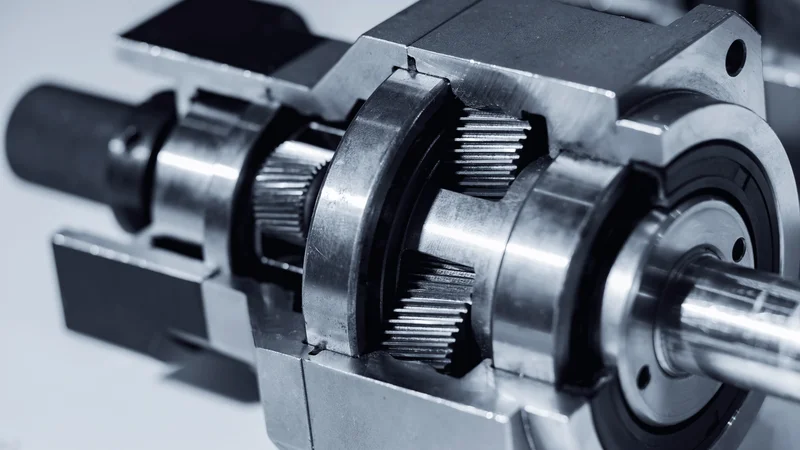
Press fits are common when attaching bearings to shafts
Key Takeaways
Press fit tolerance is set by the combination of hole tolerance and shaft tolerance.
The hole basis system is the default for machined parts, because reaming and boring tools come in fixed sizes. Shaft basis suits ground bar stock and bearing inner rings.
Lamé’s equations convert interference into contact pressure, which then gives push-out force, torque capacity, and hoop stress to check against yield strength.
Effective interference is always less than drawing interference. Surface finish asperities flatten during insertion, and rough surfaces lose the most.
Interference above roughly 0.001 mm per mm of diameter usually needs thermal assembly.
Introduction
A press fit holds two parts together with nothing but friction. You make the shaft slightly larger than the hole, force them together, and the elastic recovery of both parts generates the contact pressure that resists slipping.
Press fit tolerance is the pair of tolerance zones you put on the mating features to guarantee that interference exists across the whole production run. Get it wrong in one direction and the joint spins or walks out. Get it wrong in the other and you crack the hub or gall the surfaces.
The interference is a difference of two toleranced dimensions. A 40 mm shaft held to plus or minus 8 micrometers, in a hole held to plus or minus 12 micrometers, gives you an interference band 40 micrometers wide. The part needs to function at every point along that band, from the loosest to tightest allowable fit.
This guide covers how the ISO and ANSI systems name those bands, what numbers they produce, how to convert interference into force and stress, and how to assemble the press fit components.
Types of Engineering Fits

Every fit between a shaft and a hole falls into one of three types, decided by whether the tolerance zones overlap.
Engineering fits and their tolerance code systems are incredibly important because the same nominal diameter can be any of the three types of fits, resulting in very different mechanical outcomes.
Type of fit | Tolerance zone relationship | Result at assembly | Typical use |
Clearance fit | Shaft zone entirely below hole zone | Always a gap | Running fits, sliding fits, slip fit locations |
Transition fit | Zones overlap | Either a small gap or small interference | Accurate location with disassembly |
Interference fit | Shaft zone entirely above hole zone | Always interference | Press fit, shrink fit, permanent mechanical assembly |
Clearance Fits
A clearance fit guarantees a gap at every combination of limits. The shaft tolerance zone sits entirely below the hole zone, so even the largest shaft in the batch drops into the smallest hole without force.
Within the clearance family the size of that gap has its own names:
A running fit carries the most clearance and suits a shaft turning continuously in a plain bearing or bushing, where a lubricant film needs room to form.
A sliding fit is tighter, for parts that move along or around each other slowly and accurately, such as a spindle in a guide.
A slip fit, also called a locational clearance fit, is tighter still: the parts go together by hand and come apart the same way, but they are located accurately while assembled.
Typical uses: a shaft running in a bronze bushing, a piston in a cylinder bore, a removable dowel that must come out for service, a cover plate located on two pins.
Transition Fits
A transition fit is where the hole is fractionally smaller than the shaft. The two tolerance zones overlap, so some parts in the batch assemble with a light tap and others need a push. You accept that variation because a transition fit centers the part more accurately than a slip fit while still allowing removal.
Transition fits are used when concentricity matters more than ease of assembly, but the joint still has to come apart. Tolerances sometimes allow slight clearance at one extreme and slight interference at the other.
Typical uses: a gear or pulley located on a shaft but driven by a key rather than by friction, a coupling hub that must be pulled for maintenance, a bearing on a shaft in a light duty application where the ring load does not rotate.
Interference Fits
An interference fit is when the shaft tolerance zone sits entirely above the hole zone, so even at the worst combination of limits the shaft is bigger than the hole, and the parts can only be brought together by force, as in a press fit, or by a temperature difference, as in a forced fit. The joint is then held by nothing but friction at the interface, which is why the same joint is often called a friction fit or a force fit.
Interference fits are the choice when a joint must transmit torque or thrust without a key, a pin or a fastener, or when a part must never work loose in service. The trade off is that assembly is usually permanent, because removing the part risks damaging both surfaces.
Typical uses: a bearing inner ring on a rotating shaft, a gear pressed onto a motor shaft so it transmits torque without a keyway, a bushing pressed into a housing bore, a valve seat insert in a cylinder head, a railway wheel on its axle, dowel pins locating two castings permanently.
Recommended reading: Tolerance Stack Up Analysis: Worst Case vs RSS Methods
The ISO 286 Code System
ISO 286-1:2010 defines the ISO code system for tolerances on linear sizes.[1] It is the most widely used system globally; however, in North America, ANSI offers an imperial system (ANSI 4.1) and a metric (ANSI 4.2), which is the same as the ISO standard.
A fit designation such as H7/p6 encodes four pieces of information:
The letter gives the fundamental deviation, meaning where the tolerance zone sits relative to the nominal diameter. Uppercase letters are holes, lowercase are shafts.
The number gives the International Tolerance grade (IT grade), meaning how wide the tolerance zone is.
Uppercase first (H7/p6) means hole basis.
Lowercase first (h6/P7) means shaft basis.
For shafts, letters a through h sit below the nominal diameter and give clearance. Letters j through n straddle it and give transition. Letters p through z sit above it and give interference. The further through the alphabet you go, the heavier the press fit.
Hole Basis vs Shaft Basis
In the hole basis system the hole is always H, meaning its lower limit is exactly the nominal diameter, and you vary the shaft to change the fit. This is the default for most machining, because a hole is usually produced with a fixed size tool such as a reamer or a boring bar set to size, while a shaft diameter can be turned or ground to any value.
In the shaft basis system the shaft is always h, with its upper limit at nominal, and you vary the hole. Shaft basis makes sense when you buy precision ground bar stock and machine the mating parts to suit, or when the shaft carries several components at one diameter.
The two systems produce identical fits. H7/p6 and P7/h6 both give the same interference range at the same nominal diameter. Pick whichever leaves the tighter tolerance on the feature you can control best.
Press Fit Tolerance Tables
The table below works out six preferred hole basis fits at a 40 mm nominal diameter, using the tolerance zone values from the ANSI B4.2 and ISO 286 tables.[2] The hole is H7 throughout, so the hole diameter runs 40.000 to 40.025 mm.
Fit | Shaft limits (mm) | Result | Character |
H7/h6 | 39.984 to 40.000 | 0 to 41 µm clearance | Slip fit, locational clearance |
H7/k6 | 40.002 to 40.018 | 23 µm clearance to 18 µm interference | Transition fit, light tap |
H7/n6 | 40.017 to 40.033 | 8 µm clearance to 33 µm interference | Transition fit, mostly tight |
H7/p6 | 40.026 to 40.042 | 1 to 42 µm interference | Light press fit, locational interference |
H7/s6 | 40.043 to 40.059 | 18 to 59 µm interference | Medium drive fit |
H7/u6 | 40.060 to 40.076 | 35 to 76 µm interference | Heavy force and shrink fit |
Three things are worth noticing.
First, H7/p6 has a minimum interference of only 1 micrometer. It guarantees interference, but barely. If your joint must transmit torque rather than merely locate a part, p6 is often too light.
Second, the interference range within a single fit class is wide. H7/s6 spans 18 to 59 micrometers, a factor of more than three. Your assembly press and your stress calculation both have to cope with the maximum, while your torque capacity is set by the minimum.
Third, the numbers scale with diameter. The same H7/p6 class at a smaller 20 mm nominal diameter gives 1 to 35 micrometers of interference.
Calculating Interference, Contact Pressure, and Holding Force
Tolerance tables indicate geometry, but they don’t guarantee that a press fit will work: that it will hold the parts securely in place without risk of cracking. For this, we convert interference into pressure using Lamé’s equations for thick walled cylinders.[3]
For a solid shaft pressed into a hub of the same material, the contact pressure is:
p = (E · δ / d) · (d₀² - d²) / (2 · d₀²)
where δ is the diametral interference, d is the interface diameter, d₀ is the hub outside diameter, and E is Young’s modulus.
Worked Example
A press fit works by squeezing the shaft and hub together. The calculations below check four things: how much pressure the fit creates, how much stress that puts on the hub, how much force is needed to push the shaft out, and how much torque the joint can transmit before it slips. More interference increases the pressure, friction, and torque capacity, but also increases stress in the hub.
For our worked example, imagine a steel hub pressed onto a 40 mm steel shaft, with a hub outside diameter of 80 mm, an engagement length of 30 mm, and 30 micrometers of diametral interference. Use E = 210 GPa and a Poisson’s ratio of 0.3.
Step 1: Contact pressure
(d₀² - d²) / (2 d₀²) = (6400 - 1600) / 12800 = 0.375
p = 210 000 MPa × (0.030 / 40) × 0.375 = 59 MPa
Step 2: Hoop stress at the hub bore
This is where the hub fails if it is going to.
σ = p · (d₀² + d²) / (d₀² - d²) = 59 × 8000 / 4800 = 98 MPa
For a mild steel hub with a yield strength near 250 MPa, 98 MPa gives a comfortable margin. Halve the hub wall thickness and that margin disappears fast, which is why thin walled bushings need much lighter press fit tolerances than solid hubs.
Step 3: Push-out force
With a friction coefficient of 0.15 over the contact area:
F = μ · p · π · d · L = 0.15 × 59 × π × 40 × 30 = 33 kN
Step 4: Torque capacity
T = F · d / 2 = 33 400 N × 0.020 m = 668 N·m
Run the same calculation at your minimum interference to size the joint, and at your maximum interference to check the hoop stress and the press capacity. Note that radial interference is half the diametral value.
Because contact pressure is proportional to interference, a joint at the bottom of an H7/s6 band (18 µm) carries only about a third of the torque of the same joint at the top of the band (59 µm).
Surface Finish, Materials, and Effective Interference
Surface finish affects the interference of a joint. Machined surfaces have peaks and valleys, and the insertion process flattens the highest asperities. What remains after that plastic smoothing is the effective interference.
Rough surfaces are most significantly affected by this insertion. A turned surface with a coarse finish can give up a meaningful fraction of its designed interference during a single insertion, which is why press fit tolerances are usually paired with a specified surface finish, commonly Ra 0.8 µm or better on both mating features.
A 2025 study of rolling bearings press fitted into polyamide 6 housings tracked twelve samples across four assembly and disassembly cycles. Surface roughness fell from an initial Ra of 7.4 to 11.2 µm down to 1.8 to 3.3 µm after the fourth cycle, with most of the change happening in the first two cycles. The samples with the largest interference retained sufficient holding force after repeated maintenance, which supports the argument for over-specifying interference on any joint you expect to service.[4]
Material choice impacts effective interference in three ways:
Young’s modulus directly affects contact pressure. An aluminum hub at 69 GPa develops roughly a third of the pressure of a steel hub at the same interference, so aluminum joints need proportionally more interference.
Yield strength determines how much hoop stress the hub can carry before it takes a permanent set and loses grip.
Coefficient of thermal expansion determines whether the fit survives operating temperature. A steel shaft in an aluminum housing loosens as it heats, because aluminum expands roughly twice as fast.
Galling can occur during assembly. Pressing similar metals together, particularly stainless steel on stainless steel or aluminum on aluminum, invites adhesive transfer that tears both surfaces during insertion. To combat galling, it helps to lubricate the interface, use dissimilar materials or hardnesses, or switch to thermal assembly to avoid sliding contact entirely.
Recommended reading: Measuring Surface Roughness: A Comprehensive Guide
Assembly Methods
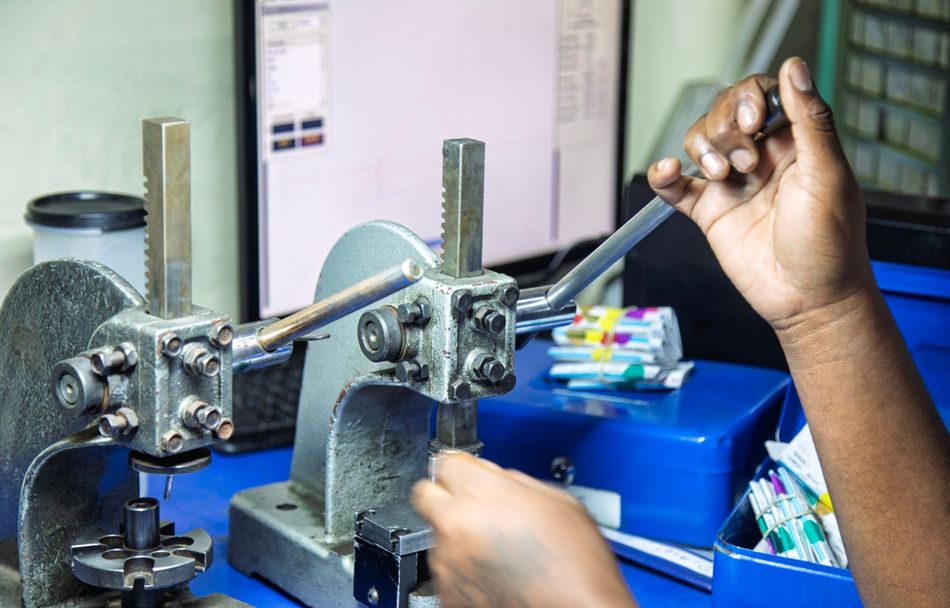
How you assemble the joint depends on how much interference you specified.
Cold press
Below roughly 0.001 mm of interference per mm of diameter, a hydraulic press or an arbor press can be used. The leading edge of the shaft should be chamfered, typically 15 to 30 degrees, to align the parts and spread the entry force, while lubrication reduces galling.
A cold press assembly is the fastest option and needs no thermal equipment, but it always involves sliding contact and therefore always loses some interference to asperity smoothing.
Shrink fit
During shrink fit assembly, the hub is heated so its bore expands past the shaft diameter, dropped into place, then left to cool.
The required temperature rise (ΔT) is interference (δ) / (bore diameter (α) × coefficient of thermal expansion (d)). This can be expressed with the formula:
ΔT = δ_total / (α · d)
A shrink fit produces no sliding contact, so it preserves the full designed interference and avoids galling entirely.
If the hub is a rolling bearing, it should be heated 20 to 30 °C above the minimum temperature needed for interference-free mounting, and never above 120 °C.[5] Above that, you risk dimensional instability and loss of hardness in the raceways.
Cryogenic
Shrinking the shaft with dry ice (about -78 °C) or liquid nitrogen (about -196 °C) is often preferable to heating, because it is less likely to alter material properties and can be faster than heating.[6] It also suits assemblies where the outer part is already installed.
With any thermal method, hold the part firmly against its shoulder while it returns to ambient. The component contracts as it cools, and if it is not seated first you will end up with a gap you cannot close.[5]
Recommended reading: Design for Manufacturing (DFM): The Engineer's Complete Guide
Bearing Seats
Rolling bearings are the most common press fit in rotating machinery, and bearing makers publish seat tolerances rather than leaving the choice to you.
For a rotating inner ring load, the bearing ring deforms under load and will creep on its seat unless the interference is sufficient, and the heavier the load, the tighter the interference must be. Precision and high speed applications get interference or transition fits specifically to suppress deflection and vibration.[7]
Bearings with a tapered bore are always mounted with an interference fit, and the fit is set by how far the ring is driven up the tapered sleeve rather than by a diameter tolerance at all.[7]
Common Mistakes and Troubleshooting
Specifying the fit but not the surface finish: A tolerance zone without a finish callout leaves effective interference undefined. Add Ra 0.8 µm or better to both features.
Forgetting form error: A hole can be within its size tolerance at every measured point and still be lobed or tapered. Without an envelope requirement or a cylindricity callout, your real minimum interference is lower than the table says. This is where press fit tolerance connects to broader tolerance stack up analysis.
Designing to nominal interference: The nominal value never occurs in production. Size torque capacity from the minimum interference and stress from the maximum.
Ignoring hub wall thickness: The Lamé term (d₀² - d²) / (2 d₀²) approaches zero as the hub gets thin. A bushing with a wall thickness of a few millimeters generates far less contact pressure than the same interference in a solid hub, and yields at a much lower interference.
Reusing a joint without re-checking: Every disassembly and reassembly cycle smooths the surfaces further and reduces holding force. If a part is serviceable, specify enough interference that it still holds after several cycles.[4]
The joint spins in service: Either the minimum interference was too low, the surface finish was too rough, or thermal expansion opened the fit at operating temperature. Check the last one first if the housing and shaft are different materials.
Conclusion
Press fit tolerance comes down to three decisions made in order. Choose hole basis or shaft basis based on which feature you can machine most reliably. Choose a fit class from the ISO 286 or ANSI tables that puts the minimum interference above what your torque requirement needs. Then verify with Lamé’s equations that the maximum interference does not push hoop stress past the hub’s yield strength.
The goal is a fit that is tight enough to perform reliably, but not so tight that assembly becomes difficult or the hub is overstressed.
Frequently Asked Questions
What is an interference fit?
An interference fit is a fit in which the shaft is always larger than the hole it goes into, at every combination of the two tolerance zones. The parts cannot be assembled by hand: they need a press, or a temperature difference that briefly opens the gap. Once assembled, elastic recovery in both parts generates contact pressure, and friction at that interface is the only thing holding the joint together.
What is an example of an interference fit?
A bearing inner ring pressed onto a rotating shaft is the most common one. Others include a gear pressed onto a motor shaft so it transmits torque without a keyway, a bushing pressed into a housing bore, a valve seat insert in a cylinder head, and a railway wheel on its axle.
What are three types of fits?
Clearance, transition and interference. A clearance fit always leaves a gap, an interference fit always leaves the shaft larger than the hole, and a transition fit overlaps the two tolerance zones so a given pair of parts may end up with either a small gap or a small interference. Which one you get is decided by the fundamental deviation letter on the shaft.
Is an interference fit the same as a press fit?
In everyday engineering use, yes. Interference fit is the formal name for the tolerance condition, where the shaft is larger than the hole. Press fit describes how you assemble it, by pressing the parts together. The one real distinction is that an interference fit can also be assembled thermally, by heating the hub or cooling the shaft, in which case nothing is pressed at all.
What tolerance is a press fit?
There is no single value. Press fit tolerance is a pair of tolerance zones whose combination guarantees interference. On a 40 mm nominal diameter, H7/p6 gives 1 to 42 micrometers of interference and H7/u6 gives 35 to 76 micrometers.
What is the difference between a press fit and a slip fit?
A slip fit is a clearance fit: the shaft is always smaller than the hole, so the parts assemble by hand and come apart the same way. A press fit is an interference fit: the shaft is always larger, and the joint is held by friction.
Is H7/p6 a press fit?
Yes, but a light one. H7/p6 is classed as a locational interference fit, meaning it is intended to locate a part accurately rather than to transmit significant torque. Its minimum interference can be as little as 1 micrometer. For torque transmission, H7/s6 or H7/u6 is usually more appropriate.
How much force does it take to press fit a part?
Push-out force is F = μ · p · π · d · L, where p is the contact pressure from Lamé’s equations.
Can you press fit without a press?
For joints with a high interference value, heating the hub or cooling the shaft opens enough clearance for the parts to drop together, and the interference forms as temperatures equalize. This avoids sliding contact, so it preserves more of the designed interference than a cold press does.
What is the maximum temperature for heating a bearing?
Do not exceed 120 °C. NSK recommends heating to 20 to 30 °C above the minimum temperature needed for interference free mounting, and staying below 120 °C to protect the bearing’s dimensional stability and hardness.
Does hole basis or shaft basis give a tighter fit?
Neither. The two systems produce identical fits, and H7/p6 gives the same interference range as P7/h6. Choose based on manufacturing convenience: hole basis when holes are made with fixed size tooling, shaft basis when you are working from precision ground stock.
References
[1] International Organization for Standardization. ISO 286-1:2010 Geometrical product specifications (GPS) — ISO code system for tolerances on linear sizes — Part 1: Basis of tolerances, deviations and fits [Internet]. Geneva: International Organization for Standardization; 2010 [cited 2026 Aug 24].
[2] Kiraly Tool. The ISO system of limits and fits: Tolerances and deviations (ANSI B4.2 and ISO 286 tolerance zone and preferred fit tables) [Internet]. Kiraly Tool; [cited 2026 Aug 24].
[3] RoyMech. Thick walled cylinders: Lamé's equations, stress analysis and interference fit calculations [Internet]. RoyMech; [cited 2026 Aug 24].
[4] Tasić M, Mišković Ž, Mitrović R, Đorđević B, Dimić A, Stamenić Z, Jeremić L. Experimental assessment of PA6 bearing housing pressed-fit for enhanced reliability and multiple maintenance process. Polymers. 2025 Nov 7;17(22):2971.
[5] NSK. Bearing mounting: mounting methods and temperature limits [Internet]. Tokyo: NSK Ltd.; [cited 2026 Aug 24].
[6] Linde. Freezing and cooling other applications [Internet]. Linde; 2025 [cited 2026 Aug 24].
[7] SKF. Seat tolerances for standard conditions [Internet]. Göteborg: SKF; [cited 2026 Aug 24].
in this article
1. Introduction2. Types of Engineering Fits3. The ISO 286 Code System4. Press Fit Tolerance Tables5. Calculating Interference, Contact Pressure, and Holding Force6. Surface Finish, Materials, and Effective Interference7. Assembly Methods8. Bearing Seats9. Common Mistakes and Troubleshooting10. Conclusion11. Frequently Asked Questions12. References