H7 Tolerance Explained: ISO 286 Hole Tolerance Charts
H7 tolerance is the default hole class in the ISO system of limits and fits. This guide explains why H7 is useful for manufacturers.

28 Aug, 2026. 10 minutes read

H7 tolerance specifies a hole that is never smaller than its nominal diameter
Key Takeaways
H7 tolerance means the hole is never smaller than nominal and never larger than nominal plus the IT7 grade. The lower deviation is exactly zero, so a 20H7 hole runs 20.000 to 20.021 mm.
The tolerance band widens with size, from 10 micrometers below 3 mm to 57 micrometers in the 315 to 400 mm range.
H7 is the preferred hole in the hole-basis system. The fit is altered by changing the shaft letter, not the hole: g6 for sliding, h6 for location, and so on.
Since the 2010 edition, an H7 callout does not control form. ISO 14405-1 made two-point size the default, so roundness and straightness need their own callout.
H7 is a machining-grade tolerance reachable by reaming, fine boring or grinding, which is why it became the default.
What H7 Tolerance Means
H7 is a tolerance class from ISO 286-1:2010, the standard that establishes the ISO code system for tolerances on linear sizes. It applies to two feature types: cylinders, and two parallel opposite surfaces.[1]
The class is defined by two things. The letter H fixes where the tolerance zone sits relative to the nominal size, and the number 7 fixes how wide that zone is.
For holes, the letter H is a special case: it puts the lower limit deviation exactly on the zero line. In the notation of the standard, eL = 0.[2] The hole is therefore never smaller than its nominal dimensions, and the whole tolerance zone sits above nominal.
That property is why H7 tolerance has become the backbone of the hole-basis system. A hole that starts at nominal can be cut with a fixed-size tool.
The Letter: Fundamental Deviation
The fundamental deviation is the deviation nearest the zero line, or where the tolerance zone begins relative to the nominal size. Hole letters run A through ZC, with uppercase for holes (internal features) and lowercase for shafts (external features).
Letters A to G sit above the zero line for holes and therefore give clearance. H sits exactly on it. J through ZC progressively move the zone downward, producing transition and then interference against a mating shaft.
The Number: IT Grade
The number is the international tolerance grade, or IT grade. ISO 286-1 defines 20 of them, IT01, IT0, then IT1 through IT18.[1]
Lower numbers mean tighter tolerance ranges. IT01 to IT6 cover gauges and high-precision work, IT7 to IT13 cover general machining and assembly, and IT14 upward cover casting and coarse fabrication.
Crucially, an IT grade is not a fixed number of micrometers. It is a band that widens with nominal size, because holding a given absolute tolerance gets harder as parts get bigger.
What H7 Tolerance Does Not Control
The 1988 edition of ISO 286-2 used the envelope criterion as the default, which meant a size callout also constrained form. The 2010 edition recommends using ISO 14405-1, which sets two-point size as the default association criterion.[2]
This means form is no longer controlled by the default specification of size. A hole can measure within its H7 limits at every two-point diameter you check and still be lobed, bowed, or tapered.
The standard notes that in many cases the diameter tolerances are not sufficient for effective control of the intended function of the fit, and that the envelope criterion, geometrical form tolerances, and surface texture requirements may be required.[2]
H7 Tolerance Chart

Because H means eL = 0, the H7 tolerance chart is simply the IT7 column with a lower deviation of zero. The values below are the standard tolerance grades from Table 1 of ISO 286-2:2010, the part of the standard that tabulates limit deviations.[2]
Nominal size (mm) | H6 | H7 | H8 | H9 |
Up to 3 | +6 / 0 | +10 / 0 | +14 / 0 | +25 / 0 |
Above 3 to 6 | +8 / 0 | +12 / 0 | +18 / 0 | +30 / 0 |
Above 6 to 10 | +9 / 0 | +15 / 0 | +22 / 0 | +36 / 0 |
Above 10 to 18 | +11 / 0 | +18 / 0 | +27 / 0 | +43 / 0 |
Above 18 to 30 | +13 / 0 | +21 / 0 | +33 / 0 | +52 / 0 |
Above 30 to 50 | +16 / 0 | +25 / 0 | +39 / 0 | +62 / 0 |
Above 50 to 80 | +19 / 0 | +30 / 0 | +46 / 0 | +74 / 0 |
Above 80 to 120 | +22 / 0 | +35 / 0 | +54 / 0 | +87 / 0 |
Above 120 to 180 | +25 / 0 | +40 / 0 | +63 / 0 | +100 / 0 |
Above 180 to 250 | +29 / 0 | +46 / 0 | +72 / 0 | +115 / 0 |
Above 250 to 315 | +32 / 0 | +52 / 0 | +81 / 0 | +130 / 0 |
Above 315 to 400 | +36 / 0 | +57 / 0 | +89 / 0 | +140 / 0 |
Above 400 to 500 | +40 / 0 | +63 / 0 | +97 / 0 | +155 / 0 |
Find the maximum allowable size by adding the upper limit to the nominal size. A 50H7 hole is 50.000 to 50.025 mm. A 100H7 hole is 100.000 to 100.035 mm. A 10H7 hole is 10.000 to 10.015 mm, since 10 falls in the above 6 to 10 band.
Picking Between H6, H7, H8 and H9
The neighboring grades trade cost against precision. H6 is roughly a third tighter than H7 and usually needs grinding or honing. H8 and H9 are comfortably reachable by boring or drilling and reaming.
As a rough guide for tolerance specifications: H6 for precision bearing fits and gauge work, H7 for general engineering fits and dowel or bushing bores, H8 for less critical location, and H9 for clearance holes where only a loose fit matters.
Rolling bearings are one case where you should not choose freely. Bearing manufacturers publish a recommended hole tolerance for each load case and housing material, so take the class from their table rather than deriving it yourself.
Shaft Tolerances That Pair with H7
In hole-basis design you hold the hole at H7 and select the shaft to set the fit. These are the shaft classes you will meet most often, with deviations in micrometers.[3]
Nominal size (mm) | g6 | h6 | k6 | n6 | p6 |
Above 3 to 6 | -4 / -12 | 0 / -8 | +9 / +1 | +16 / +8 | +20 / +12 |
Above 6 to 10 | -5 / -14 | 0 / -9 | +10 / +1 | +19 / +10 | +24 / +15 |
Above 10 to 18 | -6 / -17 | 0 / -11 | +12 / +1 | +23 / +12 | +29 / +18 |
Above 18 to 30 | -7 / -20 | 0 / -13 | +15 / +2 | +28 / +15 | +35 / +22 |
Above 30 to 50 | -9 / -25 | 0 / -16 | +18 / +2 | +33 / +17 | +42 / +26 |
Above 50 to 80 | -10 / -29 | 0 / -19 | +21 / +2 | +39 / +20 | +51 / +32 |
Above 80 to 120 | -12 / -34 | 0 / -22 | +25 / +3 | +45 / +23 | +59 / +37 |
Above 120 to 180 | -14 / -39 | 0 / -25 | +28 / +3 | +52 / +27 | +68 / +43 |
Above 180 to 250 | -15 / -44 | 0 / -29 | +33 / +4 | +60 / +31 | +79 / +50 |
Above 250 to 315 | -17 / -49 | 0 / -32 | +36 / +4 | +66 / +34 | +88 / +56 |
Above 315 to 400 | -18 / -54 | 0 / -36 | +40 / +4 | +73 / +37 | +98 / +62 |
The difference between the upper and lower deviation always equals the IT grade, so every 6-grade row above spans exactly the IT6 value for that size.
Preferred H7 Fits and What They Do
ISO and ANSI both narrow the enormous number of possible combinations down to a short preferred list. The hole-basis preferred holes are H11, H9, H8 and H7. These descriptions come from ANSI B4.2, which uses the same ISO symbols.[4]
Fit | Type | Description |
H11/c11 | Clearance | Loose running fit for wide commercial tolerances or allowances on external members |
H9/d9 | Clearance | Free running fit, good for large temperature variations, high running speeds or heavy journal pressures |
H8/f7 | Clearance | Close running fit for accurate machines and accurate location at moderate speeds |
H7/g6 | Clearance | Sliding fit, not intended to run freely, but to move and turn freely and locate accurately |
H7/h6 | Clearance | Locational clearance fit, snug fit for stationary parts that can still be freely assembled |
H7/k6 | Transition | Locational transition fit, a compromise between clearance and interference |
H7/n6 | Transition | Locational transition fit for more accurate location where greater interference is permissible |
H7/p6 | Interference | Locational interference fit for rigidity and alignment without special bore pressure requirements |
H7/s6 | Interference | Medium drive fit for ordinary steel parts, the tightest fit usable with cast iron |
H7/u6 | Interference | Force fit for highly stressed parts, or shrink fits where pressing forces would be impractical |
Note that seven of the preferred fits use an H7 hole: one reamer size covers sliding, locational, transition and light press applications. However, H7/p6 behaves as a transition fit rather than an interference fit for nominal dimensions from 0 through 3 mm.[4]
Recommended reading: Press Fit Tolerance: How to Specify Interference Fits
H7 Holes for Bearings and Dowel Pins
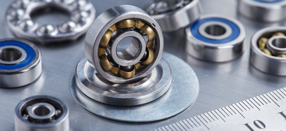
H7 is widely used for precision bores that mate with components requiring controlled clearance or interference. Two common applications are bearing housings and dowel-pin locations.
Bearing seats: An H7 bore is commonly used for bearing housings, particularly where the outer ring requires a controlled fit. The final fit depends on the bearing load, whether the inner or outer ring is rotating relative to the load, and whether axial movement is required. H7 provides a common starting point.[5]
Dowel-pin holes: H7 holes are often paired with precision dowel pins to provide repeatable location between assembled parts. The pin’s tolerance, along with the H7 hole limits, determines the resulting clearance or interference and therefore the insertion force and positional repeatability.
ANSI Inch Equivalents and Where They Differ
ANSI B4.2 is the metric standard, and it is based on the ISO millimeter system. ANSI B4.1 is the separate inch standard. It works in thousandths of an inch, and it describes a fit with one class code covering both parts rather than a hole class plus a shaft class.[6]
ANSI B4.1 family | Classes | Type | Nearest ISO 286 equivalent |
RC, running and sliding | RC1 to RC9 | Clearance | H7/g6 through H9/d9 |
LC, locational clearance | LC series | Clearance | H7/h6 |
LT, locational transition | LT series | Transition | H7/k6 and H7/n6 |
LN, locational interference | LN series | Interference | H7/p6 |
FN, force and shrink | FN1 to FN5 | Interference | H7/s6 and H7/u6 |
Within the RC family, lower numbers are tighter. RC1 is a close sliding fit for accurate location without noticeable play, RC2 is a sliding fit that turns and moves easily, RC3 is about the closest fit that can be expected to run freely, RC4 is a close running fit for accurate machinery, and RC5 and RC6 are medium running fits for higher speeds and heavier bearing pressures.[6]
ANSI B4.1 defines preferred fits only for basic sizes up to 19.69 inches, and its inch tables use tolerance grades IT4 through IT13.[6]
Worked Example: Preferred Fits at 20 mm
The table below shows preferred fits at one specific diameter. A 20 mm nominal diameter falls in the 18 to 30 band, so the H7 hole runs 20.000 to 20.021 mm throughout.
Fit | Shaft limits (mm) | Result at assembly |
H7/g6 | 19.980 to 19.993 | 7 to 41 µm clearance |
H7/h6 | 19.987 to 20.000 | 0 to 34 µm clearance |
H7/k6 | 20.002 to 20.015 | 19 µm clearance to 15 µm interference |
H7/n6 | 20.015 to 20.028 | 6 µm clearance to 28 µm interference |
H7/p6 | 20.022 to 20.035 | 1 to 35 µm interference |
H7/s6 | 20.035 to 20.048 | 14 to 48 µm interference |
H7/u6 | 20.041 to 20.054 | 20 to 54 µm interference |
Hole Basis vs Shaft Basis
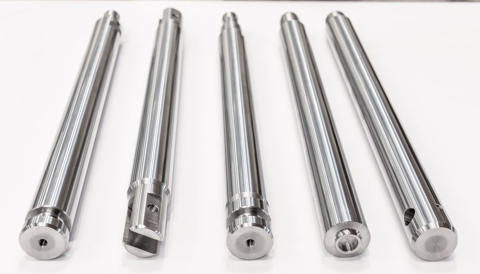
The hole-basis system holds the hole at H and varies the shaft. The shaft-basis system holds the shaft at h and varies the hole, with preferred shafts h11, h9, h7 and h6.[4]
Hole basis wins by default for machined work. A hole is usually produced with a fixed-size tool such as a reamer or a broach, so standardizing on H7 and varying the more easily adjusted shaft diameter is cheaper in tooling and gauges.
Shaft basis makes sense when you buy precision ground bar stock and machine mating parts to suit, or when one shaft diameter carries several components.
The two systems produce identical fits. H7/p6 and P7/h6 give the same interference range at the same nominal size, so choose the system on manufacturing convenience rather than on the numbers.
Achieving and Verifying H7 in the Shop
H7 is a machining-grade tolerance. Reaming, fine boring, and grinding all reach it comfortably in the sizes where H7 is common.
Dropping to H6 typically forces a finishing operation and tighter gauging, while H8 can save a small amount of time and cost but arguably not enough to justify the looser tolerance.
A plug gauge such as a go/no-go gauge checks the two-point size condition quickly, but it will not reveal form error, so a CMM or air gauge is what you need if there is an envelope requirement or cylindricity callout.
Surface finish also needs to be considered. A bore with coarse surface texture measures larger than its effective functional size once asperities flatten, which is why press and shrink fits into an H7 bore usually carry an Ra callout of 0.8 µm or better.
Recommended reading: Tolerance Stack Up Analysis: Worst Case vs RSS Methods
Conclusion
H7 tolerance is the reference point for metric engineering fits: a hole class whose lower deviation is zero and whose upper limit is the IT7 grade for that nominal size, which is 21 micrometers at 20 mm and 35 micrometers at 100 mm. Fixing the hole at H7 lets you buy one reamer, gauge one hole class, and select every fit from sliding to force by changing the shaft letter alone.
Frequently Asked Questions
What is H7 tolerance?
H7 is an ISO 286 tolerance class for holes. The H means the lower limit deviation is zero, so the hole is never smaller than nominal, and the 7 means the tolerance zone is as wide as the IT7 grade for that size.
What is the tolerance for a 20 mm H7 hole?
20.000 to 20.021 mm. The 20 mm nominal size falls in the above 18 up to and including 30 band, where IT7 is 21 micrometers, and H puts the entire band above nominal.
What is the tolerance for a 150 mm H7 hole?
150.000 to 150.040 mm. A 150 mm feature sits in the 120 to 180 band, where IT7 is 40 micrometers.
Is H7 a tight tolerance?
It is a moderate precision tolerance, mid-scale among the twenty IT grades. It is tight enough to need reaming, fine boring, or grinding rather than drilling alone, but loose enough to avoid the cost of an H6 finishing operation.
What is the difference between H7 and h7?
Uppercase H7 is a hole with its tolerance zone entirely above nominal, and lowercase h7 is a shaft with its zone entirely below nominal. At 20 mm, H7 is 20.000 to 20.021 mm while h7 is 19.979 to 20.000 mm.
What shaft goes with an H7 hole?
It depends on the fit you want. Use g6 for a sliding fit, h6 for locational clearance, k6 or n6 for transition, and p6, s6 or u6 for increasing interference.
Does H7 control roundness?
No. Since the 2010 edition, ISO 14405-1 makes two-point size the default association criterion, so an H7 callout constrains size only. Add the envelope requirement or a cylindricity tolerance if form matters.
Is ISO 286 still current?
Yes. ISO 286-1:2010 was last reviewed and confirmed in 2026 and remains current, while ISO 286-2:2010 was last confirmed in 2021 and is under systematic review. Both carry a 2013 corrigendum.
References
[1] International Organization for Standardization. ISO 286-1:2010, Geometrical product specifications (GPS), ISO code system for tolerances on linear sizes, Part 1: Basis of tolerances, deviations and fits. Geneva: International Organization for Standardization; 2010.
[2] International Organization for Standardization. ISO 286-2:2010, Geometrical product specifications (GPS), ISO code system for tolerances on linear sizes, Part 2: Tables of standard tolerance classes and limit deviations for holes and shafts. Geneva: International Organization for Standardization; 2010. Standard text and Table 1 available via published preview.
[3] Technical University of Košice. ISO tolerances for shafts and holes: ISO 286-2 deviation tables. Košice: Technical University of Košice; [cited 2026 Aug 27].
[4] Kiraly Tool. The ISO system of limits and fits: tolerances and deviations, including ANSI B4.2 preferred fit descriptions. Kiraly Tool; [cited 2026 Aug 27].
[5] D&E Bearings. Bearing housing. D&E Bearings; [cited 2026 Aug 27].
[6] Coban Engineering. ANSI standard limits and fits (ANSI B4.1-1967, R1974). Coban Engineering; [cited 2026 Aug 27].
in this article
1. What H7 Tolerance Means2. H7 Tolerance Chart3. Shaft Tolerances That Pair with H74. Preferred H7 Fits and What They Do5. H7 Holes for Bearings and Dowel Pins6. ANSI Inch Equivalents and Where They Differ7. Worked Example: Preferred Fits at 20 mm8. Hole Basis vs Shaft Basis9. Achieving and Verifying H7 in the Shop10. Conclusion11. Frequently Asked Questions12. References