Design for Additive Manufacturing: A DfAM Guide for Engineers
Design for additive manufacturing (DfAM) is the discipline of shaping a part around what a 3D printer can actually build.

13 Aug, 2026. 11 minutes read
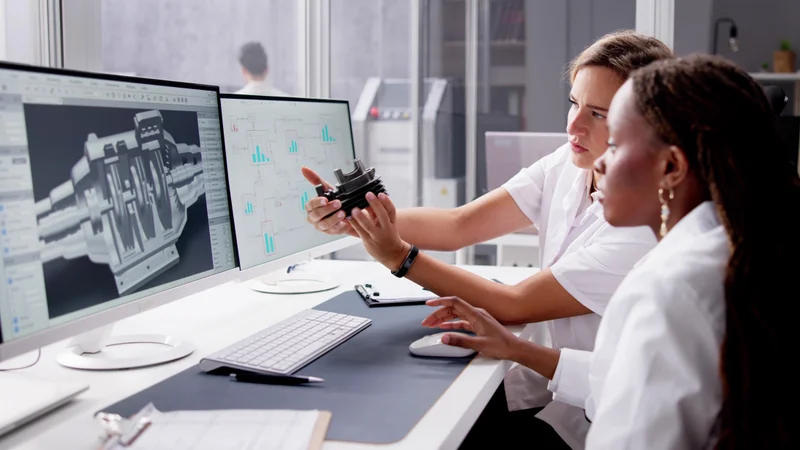
Design for additive manufacturing exploits the unique benefits of 3D printing
Key Takeaways
Design for additive manufacturing focuses on printer-specific constraints: build orientation, overhang angle, residual stress, powder removal, and anisotropy.
Geometric freedom is high in additive manufacturing, but tall and support-heavy parts can increase build cost and time.
Supports are generally not needed for overhangs up to 45 degrees from the vertical axis: a “Y” shape can just about support itself but a “T” shape cannot.
Every process has its own rules: minimum wall thickness ranges from about 0.4 mm on metal powder bed fusion to 0.8 mm on FDM, and minimum feature size from 0.2 mm on SLA to 2.0 mm on FDM.
Part consolidation, topology optimization, and lattice structures all exploit the unique strengths of additive manufacturing.
Introduction
Most parts that fail on an additive machine fail for design reasons, not machine reasons. Some are drawn for subtractive manufacturing or molding, exported to STL, and handed to a printer that has entirely different rules.
Design for additive manufacturing is the correction to that. It is design for manufacturability applied to 3D printing, and it asks a different question at every step: not “can a tool reach this feature?” but “will this feature survive being built one layer at a time?”
This guide covers the core principles of DfAM. It looks at general and technology-specific process constraints, areas of additive manufacturing that can be exploited for product improvement, post-processing considerations, and more.
Why DfAM Is Important
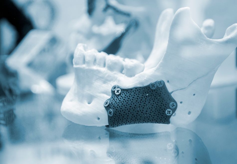
Additive manufacturing has strengths and weaknesses. ISO/ASTM 52911-1, the international standard covering design for laser-based powder bed fusion of metals, lists some of the main benefits of the technology: integration of multiple functions into one part, near-net shape production, freedom from tool accessibility and undercut limits, free-form and topologically optimized geometry, and reduced assembly through part consolidation.[1]
The standard also covers the negatives: shrinkage, residual stress, deformation from local temperature differences, stair-stepping on curved surfaces, and anisotropic mechanical properties.[1]
These pros and cons apply to most forms of additive manufacturing, not just metal PBF. These include:
Fused deposition modeling (FDM) or fused filament fabrication (FFF)
Resin 3D printing, including stereolithography (SLA)
Powder bed fusion (PBF), including direct metal laser sintering (DMLS), selective laser sintering (SLS), and multi jet fusion (MJF)
DfAM is the practice of designing parts that exploit the benefits of additive manufacturing and sidestep its limitations. At a basic level, DfAM asks, “can this design be printed?” Beyond that, it seeks to maximize the value of additive technology, from prototyping to production.[2]
Applying DfAM principles is becoming more important as additive manufacturing is increasingly used as a final-parts production technology, not simply a prototyping tool on the journey to machined or molded parts.
DfAM can be considered a subcategory of design for manufacturing (DFM). But it should not be confused with design for manufacturing and assembly (DFMA).
Process Constraints to Design Around
This article begins with the conservative side of DfAM, which involves designing parts that sidestep the constraints of additive manufacturing, largely for the purpose of preventing print defects.
Build orientation
The vast majority of additive technologies build parts on top of a print bed or build platform, and part orientation on the build platform is a useful starting point in DfAM. It affects strength, surface finish, support structure requirements, build time, and cost.
For one-off production, part height is the factor with the greatest impact on build time and cost, so parts should be oriented to keep build height minimal, leading to fewer total layers on the Z axis.[1] For larger volumes, the priority shifts to nesting as many parts as possible into each build, although varied orientation of identical parts can lead to inconsistencies.[1]
Parts should be designed so that build orientation is obvious or explicitly specified, preventing mistakes at the slicing stage.[1]
Anisotropy
Layer-by-layer construction makes parts directionally weak. In FDM, tensile strength in the XY plane is typically four to five times higher than in the Z direction, because Z-direction loads are carried by interlayer bonds rather than continuous extruded material.[3]
Processes differ in terms of how much this matters:
Process | Isotropy | Practical implication |
FDM | Anisotropic | Orient so primary tensile and fatigue loads run in-plane |
SLA | Semi-isotropic | Moderate orientation sensitivity, mostly fine after full cure |
SLS and MJF | Isotropic | Orientation driven by packing, accuracy, and finish rather than strength |
Metal powder bed fusion | Anisotropic | Orientation interacts with residual stress and support strategy |
As a general rule, treat the Z direction as your weak axis unless you have test data saying otherwise, and design ribs, bosses, and load paths accordingly.
Overhangs
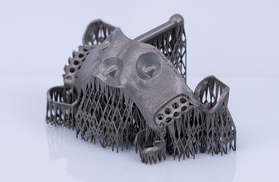
Most additive manufacturing processes, including FDM, SLA, and metal powder bed fusion, work in a way that leaves the in-progress build freestanding. This means that overhanging sections sometimes need support from underneath to prevent them from collapsing due to gravity.
SLS and MJF avoid this problem, because in-progress builds are supported by unsintered powder.[5]
For the relevant technologies, surfaces up to about 45 degrees from the vertical axis are generally self-supporting. Beyond that, the newly added material has insufficient existing material beneath it and needs support, or better, reorientation.[4]
Curved surfaces
Manufacturing processes like injection molding can achieve smooth curved surfaces, even without finishing. Because additive manufacturing works layer by layer, achieving comparable curves is not possible, and jumps between layers can be seen in the stair-step effect.
Because curved and shallow-angled surfaces are approximated by discrete layers, the printed surface deviates from the CAD geometry by an amount driven largely by layer thickness.[1]
Designs should account for imperfect curved surfaces, but surfaces can later be refined during post-processing.
Internal channels
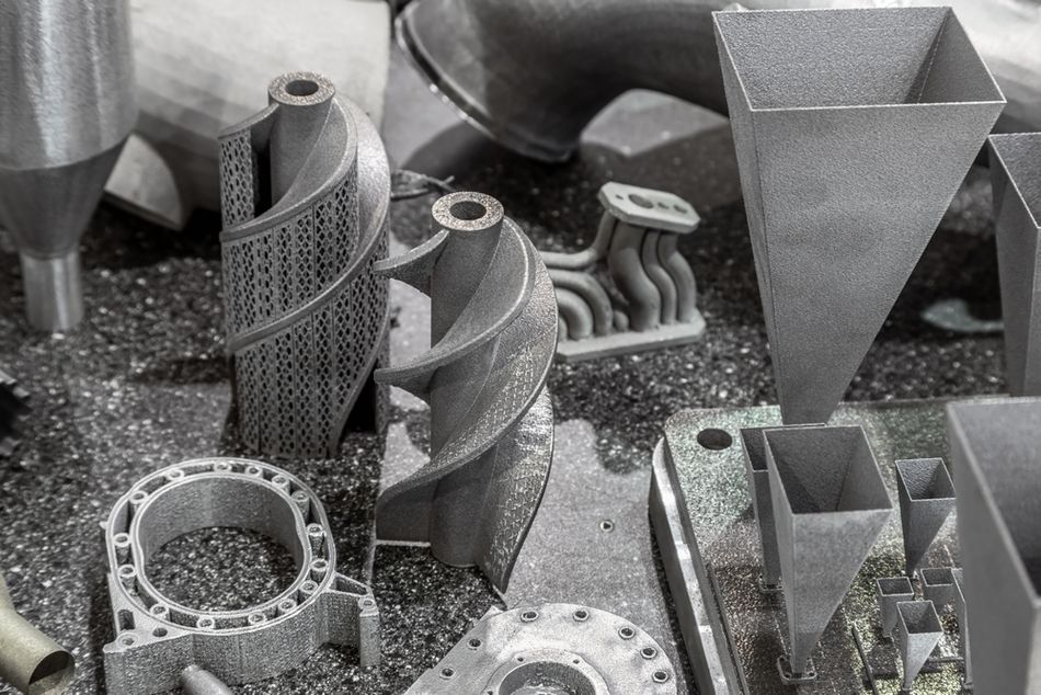
Powder bed processes let you build internal channels that no drill could produce, but they also require every cavity to have a drainage path.
Hollow parts in SLS, MJF, and metal AM need escape holes and a clear internal route so trapped powder can be removed.[4] Similarly, resin processes require drainage holes for uncured liquid resin. Processes that deposit only the exact amount of material required like FDM do not have this demand.
For internal channels, design self-supporting cross-sections. A teardrop or diamond profile prints without support where a circular hole of the same size would need it.
Wall thickness
DfAM guidelines on wall or shell thickness (perimeters) vary by process. For example, FDM parts print well when the wall width is an exact multiple of the nozzle diameter. However, some rules apply across different additive manufacturing processes:
Reinforce long thin walls with perpendicular ribs, keeping rib thickness at 50 to 75% of the wall thickness.[4]
Leave 1.5 to 2 times the wall thickness between adjacent holes, and between a hole and a part edge.[4]
Recommended reading: How to 3D Print: A Quick-Start Guide for Engineers
Process-Specific Design Rules
Some design rules are process-specific. The table below covers the most common additive manufacturing technologies, with values drawn from Protolabs Network manufacturing data.[4][6]
Process | Min wall, supported | Min wall, unsupported | Min feature size | Layer thickness | Typical accuracy |
FDM (industrial) | 0.8 mm | 0.8 mm | 2.0 mm | 100 to 300 µm | ±0.3%, floor ±0.3 mm |
SLA (industrial) | 0.5 mm | 1.0 mm | 0.2 mm | 50 to 100 µm | ±0.2%, floor ±0.13 mm |
SLS | 0.8 mm | 1.0 mm | 0.5 mm | 100 µm | ±0.3%, floor ±0.3 mm |
MJF | 0.7 mm | 1.0 mm | 0.5 mm | 80 µm | ±0.3%, floor ±0.3 mm |
DMLS (metal) | 0.4 to 0.8 mm | 0.8 to 1.5 mm | Process dependent | 20 to 50 µm typical | Machine and geometry dependent |
Actual limits depend on geometry, material, machine, and post-processing, and your service provider’s own data should override these approximate values.
Recommended reading: Types of 3D Printers: The Ultimate Guide to Additive Manufacturing Technologies
Design Techniques That Exploit Additive Manufacturing
So far we have discussed designing around the constraints of additive manufacturing. However, arguably the most important goal of DfAM is to leverage the benefits of additive technology that traditional processes do not provide.
This might involve radically rethinking how a part can be designed.
Part consolidation
Part consolidation merges an assembly into a single printed component. It removes fasteners, welds, brazes, seals, and the tolerance stack-ups that come with them. Additive manufacturing excels at part consolidation because of its high level of geometric freedom.
A good example of DfAM-informed part consolidation is GE Aerospace’s LEAP fuel nozzle tip, which has been printed over 100,000 times at GE’s North Carolina facility. The additive design reduced roughly 20 individually welded and brazed pieces to one component and cut the tip’s weight by about 25%.[7]
In the automotive industry, General Motors has used additive manufacturing to consolidate an eight-part seat bracket into a single printed component that is 20% stronger than the original assembly.[8]
When evaluating candidates, look for assemblies with many low-value fasteners, sealed fluid paths, or parts whose split lines exist purely because a mold or cutter demanded them.
Topology optimization
Topology optimization computes an efficient material distribution for a given load case, material, and set of boundary conditions.[2] The output is typically organic in appearance and often impractical to produce by subtractive manufacturing.
A review of topology optimization methods for AM shows that the strategy is widely used to reduce mass and increase stiffness.[9]
Manufacturing rules inform the topology optimization, e.g., applying overhang angle constraints so the result is self-supporting and minimum length scale constraints so the result has no features below what the machine can build.[9]
Lattice structures
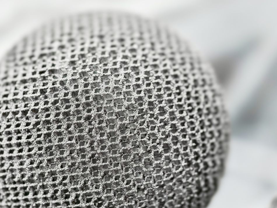
Lattice structures replace solid volume with a repeating cellular network, delivering high strength-to-weight ratios plus energy absorption, vibration damping, and thermal management.[9]
Lattices, which deliver weight reduction and cost reduction at the same time, come in three principal categories: surface-based lattices, strut lattices, and planar-based lattices.[10]
Gyroid lattices, which are a type of surface-based lattice, are self-supporting when printed, which makes them a safe default for internal infill.[9] In powder processes, keep cell sizes large enough so that powder escapes.
Generative design
Generative design extends optimization by producing many candidate geometries from goals and constraints rather than refining just one. Because additive manufacturing has such a high level of geometric freedom compared to traditional techniques, these designs can appear highly novel.
Machine learning approaches increasingly assist in navigating and ranking generative designs.
Use it for early exploration, then apply DfAM rules to the best candidates. A generative result still has to obey basic rules, including wall thickness, overhang, and powder removal constraints.
DfAM Software Tools
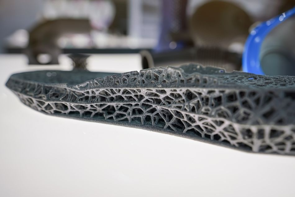
General-purpose CAD platforms such as Autodesk Fusion and SolidWorks increasingly include generative design and topology optimization, allowing designers to consider loads, material use, and manufacturing constraints within a familiar CAD workflow.
Build preparation tools like Materialise Magics are also helpful DfAM aids. They can detect and fix mesh errors in the raw CAD files, ensuring they are physically printable.
Specialist computational-design platforms provide more advanced tools for complex AM geometries. For example, nTop combines implicit modeling, topology optimization, lattice generation, and field-driven design,[2] while Altair Sulis and Inspire provide topology optimization and simulation capabilities. These tools are suited to lightweight structures that can be difficult to model using conventional CAD.
When Additive Beats Machining and Molding
DfAM includes knowing when not to print. The decision is rarely about the part alone, and typically involves time and cost constraints.
Factor | Favors additive manufacturing | Favors CNC machining or injection molding |
Volume | One-off to low hundreds | Thousands and up |
Geometric complexity | High, internal features, organic forms | Prismatic, tool-accessible |
Lead time | Days, no tooling wait | Weeks for mold or fixture design |
Material properties | Adequate, anisotropic, process-dependent | Fully dense, isotropic, well characterized |
Tolerance and surface finish | Post-processing usually required, often extensive | Basic post-processing usually sufficient |
Unit economics | Flat with complexity, high per part | Low per part at volume |
A unique economic feature of additive manufacturing is that part complexity is largely unrelated to production cost.[1] That is the opposite of CNC machining and molding, where every added feature adds tool paths or mold complexity.
This makes AM strong for rapid prototyping, low-volume production, mass customization, and complex geometries that would otherwise require multi-part assemblies. It is less suitable for high-volume simple parts, where injection molding’s per-unit cost is unbeatable once tooling is paid off.
Post-Processing Is Part of the Design
An additive part comes off the machine unfinished. Designs should factor in post-processing and any small dimensional changes that this will incur.
ISO/ASTM 52911-1 states that a machining allowance shall be provided for post-production finishing, and that specified geometric tolerances are achieved by precision post-processing.[1] In practice this means:
Add stock material to any surface with a tight tolerance or a specified surface finish, then machine it after the build.
Design support contact onto non-critical faces, because support removal leaves witness marks and degraded surface texture.
Provide tool access for support removal. Supports inside a channel you cannot reach cannot be removed.
Plan for stress relief on metal parts before removing them from the build plate, and account for the distortion that release causes.
Budget powder removal time for internal geometry, and verify drainage paths before release.
Surface finish varies by process and by face orientation. Upward-facing FDM surfaces are smoothed by the nozzle, downward-facing SLA surfaces carry support marks, and SLS and MJF lower surfaces come out grainier.[3]
Common DfAM Mistakes
Converting instead of redesigning: Importing a machining model and making minor adjustments captures almost none of the available benefit.
Ignoring the Z axis: Loading an FDM part across layer lines invites delamination at a fraction of the in-plane strength.[3]
Over-relying on supports: Excessive support use drives material waste and raises build failure risk.[1] It also creates surfaces you then have to fix.
Sealing internal voids: Trapped powder adds mass, blocks inspection, and can never be removed.
Varying wall thickness: Thin sections cool differently from thick ones, and abrupt transitions concentrate residual stress.
Leaving orientation to the operator: If orientation changes properties, specify it on the drawing.
Conclusion
Design for additive manufacturing involves defensive and offensive moves.Implement the defensive strategies first and your parts will print without defects. Then apply part consolidation, topology optimization, and lattice structures, and the parts start doing things no machined assembly could.
Start every additive project by asking what the part would look like if no mold or cutter had ever existed. Then apply the constraints in this guide to make that shape buildable.
Frequently Asked Questions
What does DfAM stand for?
DfAM stands for design for additive manufacturing. It is the application of design for manufacturing principles to 3D printing processes, accounting for layer-wise construction rather than material removal.
What is the 45 degree rule in 3D printing?
Surfaces angled up to 45 degrees from the vertical axis are generally self-supporting, while more extreme overhangs need support structures.[4] It is a guideline rather than a hard limit.
What is the minimum wall thickness for 3D printing?
It depends on the process. Typical unsupported minimums are 0.8 mm for FDM, 1.0 mm for SLA, SLS, and MJF, and 0.8 to 1.5 mm for metal DMLS.[4] Supported walls can go thinner, down to about 0.4 mm on metal powder bed fusion.
How is DfAM different from design for manufacturing?
Design for manufacturing optimizes a part for a specific production process, usually subtractive manufacturing or molding. DfAM does the same for additive processes, but it also opens design freedom that conventional DFM has to exclude, such as internal channels, lattice infill, and consolidated assemblies.
Does part orientation affect 3D printed part strength?
Yes, significantly on some processes. FDM parts show tensile strength in the XY plane roughly four to five times higher than in the Z direction, while SLS and MJF parts are close to isotropic.[3]
Which additive manufacturing technologies need support structures?
FDM needs supports for overhangs beyond about 45 degrees, SLA needs them for nearly all overhangs, and SLS and MJF need none because the surrounding unfused powder supports the part.[3] Metal powder bed fusion usually requires supports for both support and heat conduction.
Can topology optimization results always be 3D printed?
Not automatically. Raw topology optimization output often contains overhangs and features below the machine’s minimum feature size. Modern tools apply overhang angle and minimum length scale constraints during optimization so the result is manufacturable.[9]
References
[1] International Organization for Standardization. ISO/ASTM 52911-1:2019, Additive manufacturing, Design, Part 1: Laser-based powder bed fusion of metals. Geneva: International Organization for Standardization; 2019 Jul 23.
[2] nTop. Design for additive manufacturing: 3 levels of DfAM [Internet]. 2022 May 24 [cited 2026 Aug 12].
[3] Protolabs Network. How does part orientation affect a 3D print? Practical design tips for additive manufacturing [Internet]. [cited 2026 Aug 12].
[4] Protolabs Network. DFM tips for 3D printed parts with thin walls [Internet]. [cited 2026 Aug 12].
[5] Formlabs. MJF vs SLS: plastic powder bed fusion 3D printers comparison [Internet]. Formlabs; [cited 2026 Aug 12].
[6] Protolabs Network. Metal 3D printing [Internet]. [cited 2026 Aug 12].
[7] GE Aerospace. Manufacturing milestone: 30,000 additive fuel nozzles [Internet]. 2018 Oct 4 [cited 2026 Aug 12].
[8] Additive Manufacturing Media. GM seat bracket made with Autodesk generative design software [Internet]. Additive Manufacturing Media. 2018 May 3 [cited 2026 Aug 12].
[9] El Khadiri I, Zemzami M, Nguyen NQ, Abouelmajd M, Hmina N, Belhouideg S. Topology optimization methods for additive manufacturing: a review. Int J Simul Multidisci Des Optim. 2023;14:12.
[10] Santoro D. Types of lattices for additive manufacturing: terms engineers need to know. Simcenter. 2022 Dec 6 [cited 2026 Aug 12].
in this article
1. Introduction2. Why DfAM Is Important3. Process Constraints to Design Around4. Process-Specific Design Rules5. Design Techniques That Exploit Additive Manufacturing6. DfAM Software Tools7. When Additive Beats Machining and Molding8. Post-Processing Is Part of the Design9. Common DfAM Mistakes10. Conclusion11. Frequently Asked Questions12. References