3D Printing Supports: Types, Settings, and Removal (2026)
This article looks at essential strategies and solutions for optimizing 3D print support structures across FDM, SLA, and other technologies

24 Jun, 2025. 18 minutes read
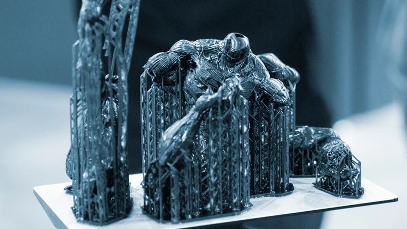
Support structures are a key part of successful 3D printing. Whether you’re working with extrusion-style printers, photopolymerization systems, or other technologies, adding supports helps prevent complex shapes from collapsing during the build. The way these 3D printing support structures are placed and printed has a big impact on print success, material costs, surface quality, and how much post-processing is needed.
Engineers designing 3D printed parts should learn to master support settings. Understanding how the extruder, nozzle, layer height, and print bed affect supports can mean the difference between a flawless print and one that fails. Beginners and experts alike can benefit from knowing when to add soluble supports or manual supports, and how to optimize infill and geometry to reduce the need for excess supports.
Whether you’re working with models requiring dissolvable metal supports or fine-tuning support placement for high-volume production, this guide provides practical strategies, software tips, and troubleshooting advice to improve your prints and streamline your workflow.
What Are 3D Printing Supports?
3D printing supports are temporary scaffold-like structures generated by a slicer or designed manually into the model. Their job is to provide a printable foundation for geometry that would otherwise be deposited, cured, or fused without enough material beneath it.
In FDM, supports give extruded filament something to land on. In resin printing, supports anchor the part and resist peel forces as each layer separates from the vat. In metal additive manufacturing, supports both stabilize geometry and conduct heat away from the part, which helps reduce distortion and residual stress.
Support structures are removed after printing, so they must be strong enough to work during the build but weak enough to detach during post processing. That balance is controlled by part orientation, support type, material choice, support density, Z-distance, interface layers, and tool access.
When Do You Need Supports in 3D Printing?
When it comes to 3D printing, especially with FDM printers, supports are all about keeping gravity in check. Since each layer is built on top of the last, there needs to be enough overlap—usually more than 50%—to stop the new layer from sagging or failing before it cools and solidifies.
That’s why overhangs are such a big deal. A common rule of thumb is the 45-degree limit—go steeper than that, and the printer might start laying plastic in mid-air.[1] But the exact limit varies depending on the type of printer you’re using. Resin printers like SLA or DLP are a different beast. Because of the way the layers peel off the resin vat, they often need supports for even gentle overhangs, sometimes as low as 20–30 degrees.
On the flip side, some powder-based systems like SLS and MJF don't need traditional 3D print supports at all. The loose powder around the part acts like scaffolding on its own. That being said, metal powder processes like DMLS do require supports.
The 45-Degree Rule
The 45-degree rule exists because each FDM layer must overlap enough with the layer below it. When the wall angle becomes too shallow relative to the layer underneath, the new extrusion has less support, begins to curl or droop, and can eventually fail.
A 45-degree overhang is usually printable because each layer still has enough overlap with the previous one. At 60 degrees from vertical, the material is extending much farther outward per layer, so cooling, extrusion width, fan performance, filament type, and layer height become much more important. For a deeper explanation, see Wevolver's guide to 3D print overhangs.
Bridging Limits
Bridging is different from overhang printing. A bridge is a horizontal span of extruded filament between two supported points. Short bridges can print cleanly because the filament is stretched across the gap and cooled quickly. Long bridges sag, separate, or create loose strands.
For common FDM materials, a conservative bridge length is often around 5–10 mm without special tuning. Better cooling, lower bridge speed, optimized flow, and stiff materials can extend that range, but long bridges should be treated as a design risk. If a bridge affects fit, sealing, airflow, load-bearing behavior, or visible quality, either support it, redesign it, split the part, or change orientation.
Resin and Metal Have Different Rules
Resin printing does not follow the same 45-degree rule. SLA, DLP, and MSLA prints are often angled and supported to manage peel forces, suction, drainage, and contact points. A feature that seems mild in FDM may still need resin supports because the part is being pulled away from a vat or film during each layer cycle.
Metal processes such as DMLS and SLM also use supports differently. Supports in metal printing are not just mechanical scaffolds. They help anchor the part to the build plate and conduct heat away from overhangs, thin walls, and stress-prone regions.
Recommended reading: Benefits of 3D Printing for Engineers and Technical Professionals
Support Structures Across Technologies
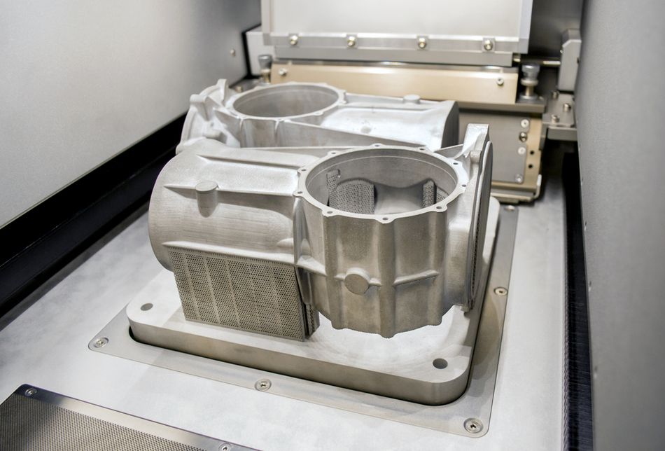
Different 3D printing technologies handle support requirements in very different ways. FDM printers typically need support structures for overhangs beyond 45 degrees, since each layer needs something solid underneath. SLA and DLP resin printers often require even more supports—even for shallow angles—because of the peeling forces during curing.
Extrusion Supports
In FDM/FFF printing, supports are typically generated in simple grid or line patterns, though some slicers offer more advanced tree-like structures to minimize material use and ease removal.[2] Their shape and density are customizable—lower densities save filament and are easier to break away, while higher densities provide stronger backing for delicate features.
The thickness of interface layers (the parts that directly touch the model) can affect surface finish: thicker interfaces provide better support but may leave marks, while thinner ones are gentler but less stable. Support size is influenced by overhang angle, with steeper angles requiring taller, more robust supports. Placement is also adjustable, with options for everywhere or only touching the build plate.
Dual-extrusion setups can use dissolvable filaments like PVA for cleaner results, especially with complex geometries.
Resin Supports
In vat photopolymerization processes like SLA and DLP, supports play a crucial role in stabilizing the part during printing. These supports are usually slender, tree-like pillars that attach the part to the build platform, countering both gravity and the peel forces that occur when each layer is pulled away from the resin vat. Unlike FDM, which supports from below, resin supports often hang beneath overhangs or angled surfaces, effectively suspending the part as it prints.
The contact points between the support and the part are kept small—typically fine tips—to reduce scarring and make removal easier. Support parameters like thickness, tip size, and distribution can be adjusted based on the part’s geometry, weight, and orientation. More complex or heavier sections need denser, stronger supports, while lightweight areas can get by with fewer.
Angling the model during setup helps reduce the total number of supports needed and can improve print success by spreading out stress and minimizing suction forces. After printing, supports are usually clipped off manually, and any remaining marks can be cleaned up through light sanding or additional UV curing.
Metal Supports
In metal 3D printing processes like DMLS (Direct Metal Laser Sintering) and SLM (Selective Laser Melting), supports serve a dual purpose: they stabilize overhangs during printing and help manage heat buildup. Since these technologies use high-powered lasers to melt metal powder layer by layer, supports act as heat sinks, drawing excess heat away from the part to reduce warping, residual stress, and distortion. This is especially important for thin walls, bridges, and overhangs, where thermal stress can easily cause failure.
Metal supports are typically blocky and solid compared to the lighter, tree-like supports seen in resin or FDM printing. They’re designed to firmly anchor the part to the build plate and resist the significant forces caused by thermal contraction. However, they’re also harder to remove—usually requiring cutting, grinding, or milling after printing.[3]
Types of 3D Printing Supports
The best support type depends on geometry. A flat mechanical bracket, a figurine, and a duct with internal channels should not use the same support strategy.
A snippet-ready answer: Tree supports in 3D printing are branching support structures that grow from the build plate or model toward overhangs, touching the part at fewer points than standard grid supports. They often use less material and are easier to remove, but they can be less stable for large, flat, heavy overhangs.
Normal or Standard Supports
Normal supports are the default support structures in many slicers. They usually build vertical columns or walls under unsupported geometry. Depending on the slicer, the internal pattern may be grid, lines, zigzag, rectilinear, snug, or another variant.
Use normal supports when the overhang is broad, heavy, or relatively flat. They are often the safest choice for mechanical parts, brackets, tooling, fixtures, and prototypes where reliability matters more than minimal material use.
The drawback is contact area. Normal supports can touch large areas of the model, especially when support interface layers are dense. That improves the underside of the print but can make removal harder and leave visible scarring.
Grid and Linear Supports
Grid or linear supports are a subset of standard supports. They create a repeated infill-like structure below the model. Grid supports provide good stiffness because the support is distributed across the area below the overhang.
Use grid supports for flat undersides, large horizontal shelves, and parts where the supported area needs consistent backing. They are less attractive for organic shapes because they can create many contact points and trap support material in concave features.
Tree and Organic Supports
Tree supports, also called organic supports in some slicers, branch upward toward the supported feature. Instead of filling the whole projected area below the overhang, they create a trunk and branching paths that touch the model only where needed.
Use tree supports for sculptural models, housings with curved outer surfaces, complex consumer-product prototypes, miniatures, and geometry where normal supports would waste material or scar visible areas. Tree supports are also useful when tool access matters because they often peel away in larger sections.
Tree supports are not always better. For a large, flat overhang, a tree structure may not provide enough uniform support across the underside. Tall, narrow tree supports can also become unstable unless brims, branch diameter, or base width are increased.
Materials and 3D Print Supports
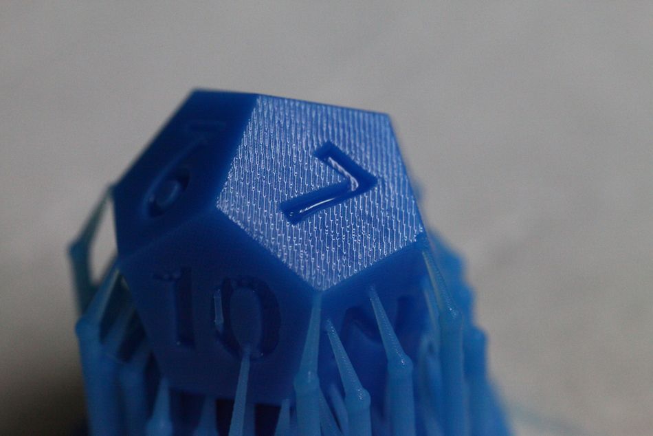
The choice of material has a major influence on how supports behave in 3D printing. Some printers are capable of printing a separate material for supports, while others use the same material as the part.
Each material brings its own combination of strength, flexibility, cooling rate, and adhesion, all of which affect how well it handles overhangs and how easily supports can be removed. Some materials tolerate steep angles and need minimal support, while others require more conservative designs to avoid print failure or surface defects.
Best Base Materials for Support Removal
When using a single-material setup, the print and its supports are made from the same filament or resin. In this case, choosing a base material that’s easy to work with can make support removal much smoother.
PLA, for example, is one of the most forgiving materials. It cools quickly, tends not to warp, and breaks away cleanly when support interfaces are properly tuned. It also works well with thin interface layers and low-density supports, which reduces scarring on the finished part.
PETG, on the other hand, is more prone to stringing and tends to bond more strongly between layers. That means supports made from PETG are often tougher to remove and may leave visible marks.
ABS is another tricky one: while it offers better strength and heat resistance, it has a tendency to warp and often requires tightly bonded, denser supports—making cleanup more difficult.
Flexible materials like TPU are an interesting exception. While they don’t typically require as much support for steep angles (thanks to their elasticity), the supports they do need can be hard to remove cleanly unless spacing and interface layers are carefully tuned.
In resin printing, support removal is more dependent on slicer settings and contact point design than on the resin type itself. However, more brittle resins tend to snap off more cleanly, while flexible or toughened resins may stretch or tear, making post-processing a bit more involved.
For more material background, see Wevolver's guides to 3D printer filament and PLA.
Dedicated Support Materials: Dissolvable, Breakaway, and More
For more advanced setups—typically involving dual-extrusion FDM printers or specialized workflows—dedicated support materials offer big advantages. Dissolvable supports, such as PVA or BVOH, are water-soluble filaments that dissolve completely after printing. These are ideal for complex geometries, internal cavities, or detailed models where traditional supports would be hard to reach or remove without damage.
PVA pairs best with PLA due to similar printing temperatures, while BVOH works with a wider range, including PETG.
Breakaway support materials, such as Ultimaker Breakaway or certain HIPS formulations, are designed to snap off cleanly with minimal force. They don’t dissolve, but they separate easily from the model without leaving much residue. These are great when faster post-processing is needed and water-soluble options aren’t practical.
Support Material | Compatible Base Materials | Removal Method | Notes |
PLA | PLA | Breakaway | Easy to remove with proper settings. Good for basic geometries. |
PVA | PLA, Nylon (low temp) | Water-soluble | Ideal for complex or enclosed features. Moisture-sensitive. |
BVOH | PLA, PETG, Nylon | Water-soluble | Dissolves faster than PVA. More versatile and moisture-resistant. |
HIPS | ABS | Dissolves in limonene | Strong, clean results. Requires chemical handling and ventilation. |
Breakaway | PLA, PETG, CPE, etc. | Breakaway | Designed for clean removal without post-processing chemicals. |
Slicer Settings for 3D Printing Supports
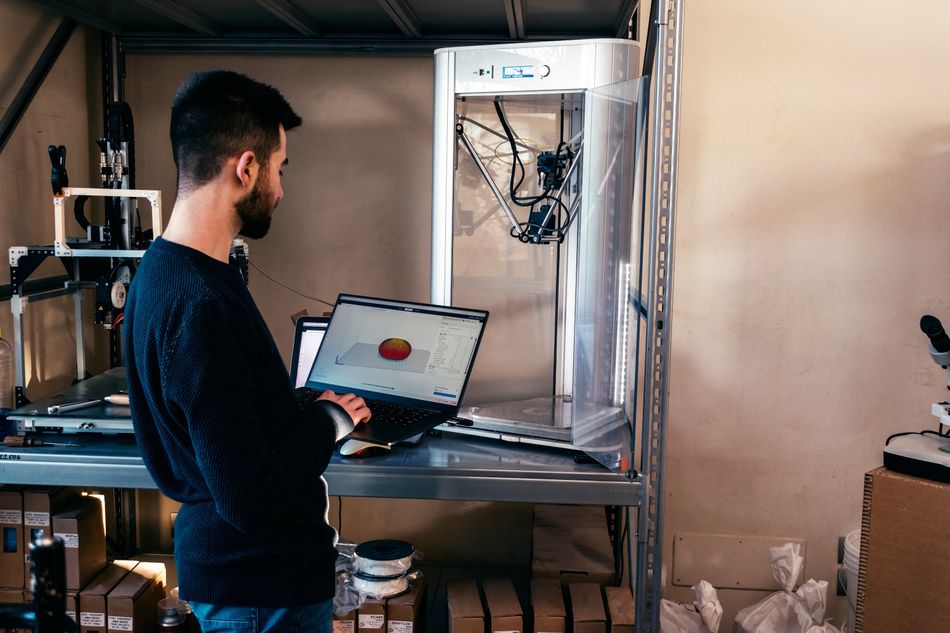
Support quality is controlled mostly in the slicer. The most important settings are support type, support density or pattern spacing, Z-distance, interface layers, support placement, and overhang threshold.
Cura, PrusaSlicer, Bambu Studio, and OrcaSlicer expose similar concepts through different menu names. UltiMaker's Cura documentation describes support density and line distance as linked support settings, Bambu Lab documents Top Z Distance as the support-to-model gap, and OrcaSlicer documents support type, style, threshold angle, and tree support parameters in its support settings.
Support Type
Support type determines the geometry of the support structure. For broad flat features, start with normal, grid, snug, or rectilinear supports. For complex surfaces and visible exterior geometry, start with tree or organic supports.
Support Density and Pattern Spacing
Support density controls how much material is printed inside the support structure. Pattern spacing is the same idea expressed as distance between support lines.
For easy removal, lower density is usually better. For better underside quality, higher density or a dense interface is better. A practical starting point for same-material FDM supports is often 10–15% for easy removal and 20–30% for stronger support. Increase density only where the support is failing or where the underside quality matters.
Z-Distance
Z-distance is the vertical gap between the support and the printed part. It is one of the most important settings for support removal.
If Z-distance is too small, supports fuse to the part. If it is too large, the supported surface sags and becomes rough. For same-material FDM supports, a common starting point is one layer height, such as 0.2 mm for a 0.2 mm layer print. PETG may need more clearance because it tends to bond strongly. Soluble or dedicated support interfaces can often use a smaller gap, sometimes zero-gap contact, because the support material can be dissolved or separated from the model. Bambu Lab specifically notes that dedicated support filament can allow Top Z Distance of 0 while still enabling removal.
Interface Layers
Interface layers, sometimes called support roof, support floor, or dense support interface, are the layers between the support structure and the model.
More interface layers improve the supported surface but increase adhesion and removal force. Fewer interface layers make supports easier to remove but may leave rougher undersides. For visible or functional undersides, interface tuning often matters more than support density.
Overhang Threshold
The overhang threshold tells the slicer when to generate supports. A conservative FDM threshold is around 45 degrees. Raising or lowering the value changes how aggressively the slicer creates supports, but different slicers define and visualize this setting differently.
Do not rely only on the automatic result. Always inspect the sliced preview for unsupported islands, long bridges, thin support towers, and supports touching critical cosmetic surfaces.
Automatic Support Generation
Modern 3D printing relies heavily on software to automatically generate support structures, which are essential for printing complex geometries and overhangs without manual design. These automatic supports analyze the model’s shape and determine where additional material is needed to ensure print success, saving time and reducing guesswork.
Slicer software examines the 3D model layer by layer, identifying overhangs and unsupported sections based on parameters like overhang angle thresholds (often around 45 degrees for FDM). It then places support structures beneath these areas, optimizing for minimal material use while maintaining stability. Users can customize support density, pattern (grid, lines, or tree-like structures), placement (everywhere or only on the build plate), and interface layers to balance print quality, ease of removal, and material consumption.
Advanced slicers also account for print orientation and surface finish, and some let users manually add or remove supports for tricky areas.
AI Support Generation
Artificial intelligence is beginning to play a role in support generation by analyzing complex geometries and predicting the best support strategies more intelligently than traditional algorithms.
AI-driven tools can suggest optimal support placement, density, and even propose part orientations to minimize support use. These systems learn from vast datasets of successful prints to improve accuracy and efficiency, helping reduce material waste and post-processing time.
As AI integration matures, it promises to make support generation more automated, adaptive, and reliable across different printers and materials.
Popular 3D Printing Software for Support Generation
Here are some of the leading software tools known for their effective automatic support features:
UltiMaker Cura: Offers user-friendly controls, tree support structures, and detailed customization options for density and interface layers.
PrusaSlicer: Provides advanced support editing tools, including variable density supports and support blockers for fine-tuning.
Simplify3D: Professional-grade slicer with extensive support customization, allowing precise control over placement and interface layers.
Chitubox: Widely used for resin printing, featuring adjustable contact point sizes and flexible support placement.
IdeaMaker: Intuitive slicer with smart automatic supports and customization, popular among Raise3D printer users.
Recommended reading: Cura Support Settings, from Angles to Z Distance
Support Removal
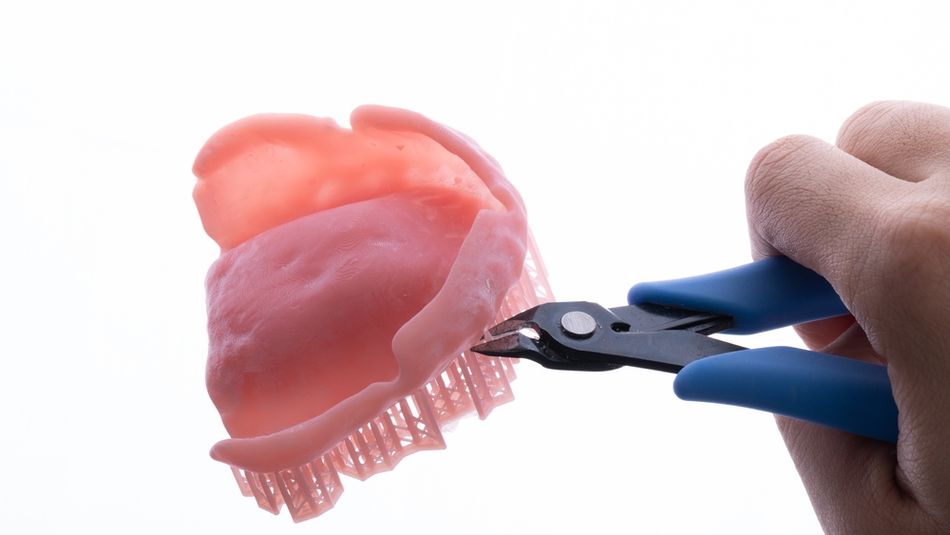
Support removal is a critical post-processing step in 3D printing that varies widely depending on the material, printer technology, and type of supports used. Whether removing plastic scaffolding from an FDM print, fragile resin supports from an SLA part, or robust metal structures from a DMLS component, the goal is to efficiently detach supports without damaging the model’s surface or compromising dimensional accuracy.
Physical Removal Techniques
For many 3D prints—especially those from FFF/FDM printers—manual removal remains the most common method. Supports are designed to break away with moderate force and are snapped or clipped off using hand tools such as flush cutters, needle-nose pliers, or hobby knives. This is often followed by sanding or filing to smooth any rough spots or support marks.
In resin printing, supports tend to be thinner and more delicate, so precise cutting tools like fine flush cutters are used to carefully trim away support pillars without cracking or tearing the model.
For metal prints, physical removal is far more demanding: heavy-duty tools like saws, grinders, or CNC milling machines are used to cut away thick support structures, requiring skilled operators to avoid damaging critical features.
Chemical and Dissolving Methods
Dissolvable support materials have transformed post-processing for FDM prints, especially when using dual extrusion. Materials like PVA and BVOH dissolve in water, allowing users to soak prints in tanks or ultrasonic baths to gently remove supports without mechanical force.
Ultrasonic cleaning further accelerates this process by agitating water around the model to dissolve supports more quickly and thoroughly. In resin printing, cleaning usually involves baths of isopropyl alcohol (IPA) to remove uncured resin, which also helps loosen support attachments.
For metal parts, chemical etching or acid baths are less common due to safety concerns but can be used in specialized settings to remove residual support material or surface oxides after mechanical removal.
Specialized Hardware and Processes
Ultrasonic cleaners have become popular for both dissolvable FDM supports and resin print cleanup, improving removal efficiency and reducing manual labor.
Pressure washers or water jets may also be used to rinse away softened support material, particularly for complex geometries.
Abrasive blasting (such as bead blasting) of metal parts is a standard step after cutting supports, smoothing surfaces and removing leftover particles.
Thermal treatments frequently follow support removal in metal printing to relieve stresses introduced during cutting or grinding.
Recommended reading: How to Remove Supports from 3D Prints
Designing to Minimize or Avoid Supports
The best support is often the one you design out of the part. Design for additive manufacturing means shaping the model so it prints reliably with fewer sacrificial structures, less post processing, and better surface quality.
Use Self-Supporting Angles
For FDM, keep overhangs at or below a self-supporting angle wherever possible. A 45-degree chamfer is often printable without supports, while a sharp 90-degree ledge usually is not.
This is especially useful for bosses, mounting features, underside transitions, and enclosure details. A small chamfer can remove a large support region without changing the functional envelope of the part.
Prefer Chamfers Over Fillets on Downward-Facing Edges
Fillets are useful for stress reduction, but downward-facing fillets can create gradually worsening overhangs that need support. Chamfers are often more printable because they maintain a constant self-supporting angle.
Use fillets where they improve strength, flow, or handling. Use chamfers where the goal is support-free printing.
Reorient the Part
Part orientation changes everything: support volume, print time, surface finish, anisotropic strength, and dimensional accuracy. A part may be difficult in one orientation and easy in another.
Place critical cosmetic or sealing surfaces away from supports. Orient holes so they print as vertical holes or teardrops rather than unsupported horizontal circles. Tilt resin parts to reduce suction and cross-sectional area. For metal parts, orientation should also account for thermal stress and support removal access.
Split Complex Models
Splitting a model into multiple printable pieces can eliminate supports and improve surface finish. This is often the best approach for ducts, housings, manifolds, cosplay parts, jigs, and large prototypes.
Use alignment pins, dovetails, screws, adhesive joints, or welded seams depending on the application. Splitting adds assembly time, but it can reduce print time, waste, and cleanup.
Design Bridges Deliberately
Short bridges are printable. Long bridges are risky. If a bridge is required, keep it short, provide anchor points, orient the bridge along a favorable direction, and consider adding a slight arch or chamfered underside.
For circular horizontal holes, consider teardrop or diamond-shaped holes. These preserve functional clearance while making the upper region self-supporting.
Designing for Support Removal
Although designing to minimize supports is good practice, removing the necessary supports should be as painless as possible. It’s wise to leave at least 2.5 mm of clearance around support structures so you can fit tools in to snap or cut them away without damaging the part.
Using thin break-away features—usually 0.2 to 0.5 mm thick—helps supports separate cleanly without tearing or leaving rough patches. For parts with enclosed spaces, incorporating support escape holes lets you flush out dissolved supports or reach tricky spots.
Adding interface layers—thin buffer layers between support and model—with a gap of 0.1 to 0.2 mm can also help reduce adhesion marks and make supports easier to remove.
The type of support matters, too. Tree supports, which branch out and touch the model at minimal points, generally leave a better surface finish and use less material. Meanwhile, dissolvable supports offer the cleanest removal but come with higher material costs and require compatible printers.
Industry-Specific Requirements
Different industries have unique demands when it comes to supports.
Aerospace: Precision and weight are everything here. Supports must be removable without altering critical dimensions, and they often help dissipate heat for tough metals like titanium or Inconel. Smart support design can reduce support volume by up to 60%, cutting weight and cost.
Medical Devices: Regulations like FDA guidelines require validated processes for support removal to ensure patient safety. Biocompatible support materials and smooth surface finishes are essential, and parts must also withstand sterilization procedures without degrading.
Automotive: With high production volumes, efficiency is key. Automated support removal and recycling of support materials are becoming standard. Support strategies must integrate smoothly with quality control and manufacturing workflows to keep costs down and maintain part consistency.
Troubleshooting Common Support Issues
Support failures usually come from poor adhesion, weak support geometry, excessive support height, incorrect Z-distance, too little interface, bad cooling, or slicer overconfidence.
Supports Break During Printing
If supports detach or snap mid-print, increase support base width, add a brim, increase support density, use a stronger support type, or reduce print speed around support structures. Tall, thin tree supports may need larger branch diameters or additional stability.
Supports Are Too Hard to Remove
If supports fuse to the model, increase Z-distance, reduce interface layers, reduce interface density, lower support density, or switch to a breakaway or soluble interface. PETG often needs more clearance than PLA.
Supported Surfaces Look Rough
If supported undersides sag, reduce Z-distance, add interface layers, increase interface density, improve cooling, reduce overhang speed, or reorient the model. Do not simply increase all support density unless the support is unstable.
Tree Supports Fail
Tree supports can fail if they are too tall, too thin, or poorly attached to the build plate. Add a brim, increase branch diameter, reduce branch angle, use a stronger tree style, or switch to normal supports for broad flat overhangs.
Resin Supports Leave Marks
Reduce contact tip size only if supports are not failing. Move supports to non-critical areas, angle the part differently, use more smaller supports instead of fewer large supports, and trim carefully before sanding.
Support Failure Diagnosis and Prevention Checklist
Increase support base width by 15-25% and add brims for better adhesion
Ensure support base diameter ≥ 3× support column diameter
Use support column thickness between 1.3–1.6 mm; avoid height-to-width ratios >10:1
Add cross-bracing to tall supports for added stability
Reduce FDM support interface overlap to 0.1–0.2 mm
Use spherical contact tips (0.3–0.5 mm) for SLA supports instead of flat contacts
Calibrate interface gaps precisely (0.15 mm for PLA, 0.2 mm for ABS, 0.1 mm for PETG)
Use support densities of 10-15% for easy removal, 20-30% for stable support
Apply progressive wet sanding (400 to 1200 grit) to reduce surface roughness after support removal
Conclusion
Ultimately, success in 3D print supports depends on a systematic approach that combines thoughtful design, material choice, process control, and continuous improvement. By following the strategies outlined in this guide, engineers can achieve significant returns through reduced material use, improved part quality, and faster production cycles across all major 3D printing technologies.
Frequently Asked Questions
What angle requires support in 3D printing?
For FDM/FFF, supports are usually needed for overhangs over 45°, but some materials can handle up to 60–70°. Resin printers like SLA/DLP need supports at much lower angles due to how layers peel. Powder bed systems like SLS don’t need supports because the powder holds the part.
Can you 3D print without supports?
Yes, many parts can be printed without supports if they are designed with self-supporting angles, short bridges, teardrop holes, chamfers, and good orientation. Splitting a model into multiple pieces can also eliminate supports.
What are tree supports in 3D printing?
Tree supports are branching support structures that grow toward unsupported areas and touch the model at fewer points than normal grid supports. They are useful for organic shapes, curved surfaces, miniatures, and parts where easy removal matters.
Are tree supports better than normal supports?
Tree supports are often better for complex external geometry because they use less material and can be easier to remove. Normal or grid supports are often better for large, flat overhangs because they provide more uniform backing.
How do I minimize supports in my 3D prints?
Print parts oriented with the largest flat surface down, use 45° chamfers instead of sharp overhangs, add self-supporting shapes like teardrop holes, and split complex models into smaller parts.
What are the best support materials for different filaments?
PLA works well with water-soluble PVA or BVOH supports. ABS pairs best with HIPS or BVOH. PETG prefers BVOH for easy removal.
How much do supports add to 3D printing costs?
Supports add about 10–30% more material and increase costs by up to 40% when factoring in post-processing. Optimizing supports can cut material use and cleanup time by over half, saving money after dozens of parts.
What's the best way to remove supports without damaging parts?
For dissolvable supports, warm water with ultrasonic baths speeds removal. For others, use proper tools like flush cutters and pliers after the print cools. Printing with a 0.15–0.25 mm gap between supports and part makes removal easier.
References
[1] Mittal Y, Agarwal V, Yadav D, Avegnon KL, Sealy M, Kamble P, Gote G, Patil Y, Mehta A, Mandal P, Karunakaran KP. A mechanistic model for overhang limits in additive manufacturing. Progress in Additive Manufacturing. 2025 May 17:1-20.
[2] Vishnu Prasad KR, Sharma GK. Template Based Generation of Tree-Like Support Structure for Additive Manufacturing. InNational Conference on Multidisciplinary Analysis and Optimization 2025 (pp. 181-189). Springer, Singapore.
[3] Cao Q, Bai Y, Zhang J, Shi Z, Fuh JY, Wang H. Removability of 316L stainless steel cone and block support structures fabricated by Selective Laser Melting (SLM). Materials & Design. 2020 Jun 1;191:108691.
in this article
1. What Are 3D Printing Supports?2. When Do You Need Supports in 3D Printing?3. Support Structures Across Technologies4. Types of 3D Printing Supports5. Materials and 3D Print Supports6. Slicer Settings for 3D Printing Supports7. Support Removal8. Designing to Minimize or Avoid Supports9. Designing for Support Removal10. Industry-Specific Requirements11. Troubleshooting Common Support Issues12. Support Failure Diagnosis and Prevention Checklist13. Conclusion14. Frequently Asked Questions15. References