Active Low Pass Filter Design and Implementation
Active low-pass filters use op-amps, resistors, and capacitors to pass low-frequency signals while attenuating higher frequencies. This article covers first-order and second-order filter design, Sallen-Key and MFB topologies, cutoff frequency, Q factor, and applications.

29 May, 2026. 16 minutes read

Key Takeaways
Active low-pass filters use operational amplifiers, resistors, and capacitors to pass low-frequency signals while attenuating high-frequency noise and interference.
First-order active low-pass filters provide a −20 dB/decade roll-off, while second-order filters increase attenuation to −40 dB/decade.
Popular active filter topologies include Sallen-Key and multiple-feedback (MFB) designs, each suited for different gain and Q-factor requirements.
The cutoff frequency of an active low-pass filter is commonly calculated using the equation: fc = 1 / (2πRC)
Butterworth, Chebyshev, and Bessel responses allow engineers to balance flatness, roll-off steepness, and phase response.
Op-amp parameters such as the gain-bandwidth product (GBW) and slew rate directly affect the performance and stability of active filters.
Active low-pass filters are widely used in audio electronics, anti-aliasing circuits, instrumentation, sensor systems, and signal conditioning applications.
Higher-order active filters are created by cascading first-order and second-order stages to achieve sharper frequency attenuation.
Introduction
Active low-pass filters are analog circuits designed to pass low-frequency signals while attenuating unwanted high-frequency components. Unlike passive low-pass filters, which rely solely on resistors, capacitors, and inductors, active low-pass filters use operational amplifiers (op-amps) to provide voltage gain, impedance isolation, and improved control over frequency response. These advantages make active filter circuits widely used in audio electronics, instrumentation systems, communication devices, embedded systems, and signal processing applications.
In modern electronic design, active low-pass filter circuits are commonly used for noise reduction, anti-aliasing before analog-to-digital conversion, waveform smoothing, and sensor signal conditioning. Because active RC filters eliminate the need for bulky inductors, they are compact, cost-effective, and easier to tune for low-frequency applications. Their ability to provide amplification while maintaining signal integrity makes them especially valuable in analog circuit design and precision electronics.
Active vs Passive Low-Pass Filters
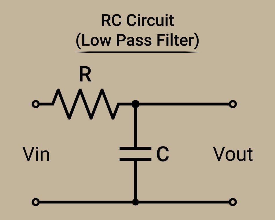
Low-pass filters can be broadly classified into passive and active filter circuits. Passive low-pass filters use only resistors, capacitors, and inductors to attenuate high-frequency signals. While passive RC filters are simple and inexpensive, they cannot provide voltage gain and are strongly affected by source and load impedance. In higher-order passive filters, inductors are often required, but these components become bulky, costly, and less practical at low frequencies.
Active low-pass filters overcome many of these limitations by incorporating operational amplifiers (op-amps) with resistors and capacitors. The op-amp provides amplification, buffering, and impedance isolation, allowing the filter to maintain a stable and predictable frequency response when connected to other circuit stages. Because active RC filters eliminate the need for inductors, they are more compact, cost-effective, and easier to integrate into modern analog electronics and embedded systems.
One of the major advantages of active low-pass filters is their ability to provide voltage gain while simultaneously filtering unwanted high-frequency content. Their high input impedance minimizes loading effects on the signal source, while low output impedance allows multiple filter stages to be cascaded without significantly altering circuit behavior. Active filters also offer better control over cutoff frequency, gain, and Q factor, making them highly adaptable for precision analog signal processing applications.
Despite these advantages, active filters are limited by the performance characteristics of the op-amp itself. Parameters such as gain-bandwidth product (GBW), slew rate, input noise, and supply voltage range directly influence filter accuracy and stability. At very high frequencies, especially in RF applications, passive LC filters are often preferred because op-amp bandwidth limitations can reduce active filter performance.
Passive filters remain common in simple attenuation circuits and high-frequency communication systems, while active low-pass filters are widely used in audio electronics, instrumentation, anti-aliasing systems, sensor interfaces, and analog signal conditioning. Similar design principles are also widely applied in analog amplifiers and signal conditioning circuits.
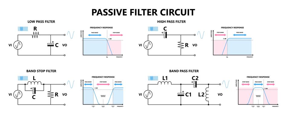
Recommended reading: Difference between Active and Passive Filters?
First-Order Active Low-Pass Filter
A first-order active low-pass filter is one of the most common filter circuit designs used in analog electronics and signal processing. It combines a basic RC filter with an operational amplifier to pass low-frequency signals while attenuating unwanted high-frequency components above a defined cutoff frequency. Compared with a passive RC filter, an active low-pass filter provides voltage gain, improved impedance matching, and better overall frequency response stability.
In the simplest topology, a resistor and a capacitor create the RC filter network, while the op-amp acts as a buffer or amplifier stage. At low frequency, the capacitor presents high impedance, allowing most of the input signal to appear at the output. As frequency increases, capacitor impedance decreases, causing the output signal amplitude to gradually fall.
Recommended reading: Low Pass Filter vs High Pass Filter – Theory, Design, and Applications
A common non-inverting configuration uses feedback resistors to set the closed-loop gain:
A = 1 + (Rf / R1)
where:
A is the voltage gain
Rf is the feedback resistor
R1 is the input resistor
Transfer Function and Cutoff Frequency
The transfer function of a first-order active low-pass filter is:
H(s) = A / (1 + sRC)
The cutoff frequency is determined by:
fc = 1 / (2πRC)
where:
R is the resistor value in ohms
C is the capacitor value
fc is the cutoff frequency
Below the cutoff frequency, the frequency response remains nearly constant. Once the signal exceeds the cutoff frequency, attenuation increases at a rolloff rate of −20 dB per decade. This gradual reduction in signal amplitude makes first-order filters useful for waveform smoothing, noise reduction, and low-frequency signal conditioning. The phase response also changes with frequency. At very low frequency, the output signal remains nearly in phase with the input. At higher frequencies, the phase gradually shifts toward −90°.
Recommended reading: What Is a Low-Pass Filter? Theory, Design & Practical Implementation
Inverting First-Order Filter
An active low-pass filter can also use an inverting operational amplifier configuration. In this topology, the RC filter network is placed in the feedback path of the op-amp.
The transfer function becomes:
H(s) = −(Rf / R1) / (1 + jωRfC)
The negative sign indicates that the output signal is inverted by 180°. This topology allows gain values greater than unity gain and is commonly used in instrumentation, analog control systems, and sensor interface circuits. Although first-order filters are simple and cost-effective, they provide only moderate attenuation at high frequencies. Applications requiring steeper rolloff and tighter filter design specifications generally use second-order low-pass filter topologies.
Second-Order Low-Pass Filter Topologies
A second-order low-pass filter improves attenuation performance by increasing the rolloff to −40 dB per decade. These filters also allow engineers to control the quality factor (Q), damping, and transient frequency response characteristics more precisely. Two of the most widely used active low-pass filter topologies are the Sallen-Key filter and the multiple-feedback (MFB) filter. Both designs use two resistors, two capacitors, and an op-amp, but they differ in gain structure, sensitivity, and circuit behavior.
Sallen-Key Low-Pass Filter
The Sallen-Key topology is one of the most popular active filter designs in analog electronics because it is simple, stable, and easy to implement. It is also known as a voltage-controlled voltage source (VCVS) filter. In a Sallen-Key active low-pass filter, the operational amplifier operates as either a unity gain buffer or a non-inverting amplifier. The resistor-capacitor network determines the cutoff frequency and frequency response shape.
The voltage gain is:
K = 1 + (R4 / R3)
The general transfer function is:
H(s) = K / [s^2 R1 R2 C1 C2 + s(R1 C1 + R2 C1 + R1 C2(1 − K)) + 1]
The cutoff frequency is:
fc = 1 / (2π √(R1 R2 C1 C2))
By selecting different resistor and capacitor ratios, engineers can design Butterworth, Chebyshev, or Bessel filter responses depending on the required frequency response and attenuation characteristics.
A simplified equal-component version is widely used in practical circuit design:
R1 = R2 = R
C1 = C2 = C
The transfer function simplifies to:
H(s) = K / [s²(RC)² + sRC(3−K) + 1]
For equal-value Sallen-Key filters:
fc = 1 / (2πRC)
Q = 1 / (3−K)
A Butterworth response requires:
Q ≈ 0.707
which corresponds to:
K ≈ 1.586
Butterworth active low-pass filter designs are extremely common because they provide a maximally flat frequency response with no ripple in the passband. Increasing the gain raises the Q factor and produces more peaking near the cutoff frequency. Sallen-Key circuit design concepts are also closely related to active high-pass filter implementations, where the positions of the resistor and capacitor networks are reversed to create high-pass frequency response behavior.
Recommended reading: Active High Pass Filter: Theory, Design, and Applications Multiple Feedback (MFB) Low-Pass Filter
The multiple-feedback topology uses an inverting op-amp configuration with multiple feedback paths around the operational amplifier. Compared with the Sallen-Key topology, MFB filters provide better control of the Q factor and improved high-frequency performance.
The circuit contains:
two capacitors,
three resistors,
and one op-amp.
The natural frequency is approximately:
ω0 = 1 / √(C1C2R2R3)
Unlike Sallen-Key filters, multiple-feedback active low-pass filter circuits can achieve high Q values without requiring excessive amplifier gain. This makes them useful in narrow-band analog applications and higher-order filters where sharper attenuation is needed.
MFB filters are commonly used when:
Q > 3,
higher closed-loop gain is required,
tighter frequency response control is needed,
or improved high frequency stability is important.
Because the topology uses an inverting amplifier, the output signal is phase inverted. However, the design generally offers lower sensitivity to component tolerance and better overall stability compared with Sallen-Key configurations.
Texas Instruments frequently recommends multiple-feedback topologies for precision analog filtering applications requiring controlled rolloff and narrow bandwidth response.
Topology Comparison
Topology | Configuration | Inverting | Gain Range | Key Advantages |
Sallen-Key | Non-inverting op-amp topology | No | Unity gain to moderate gain | Simple circuit design, low component count, widely used for Butterworth and Bessel filters |
Multiple-Feedback (MFB) | Inverting op-amp topology | Yes | Gain can exceed unity | Better Q-factor control, improved attenuation, lower sensitivity to component variation |
Both topologies are widely used in active filter design, and the best choice depends on the required frequency response, impedance characteristics, gain, and application requirements.
Filter Response Types
The frequency response of an active low-pass filter determines how the circuit behaves across different frequencies. While all low-pass filters are designed to pass low-frequency signals and attenuate high-frequency components, the way they transition around the cutoff frequency can vary significantly depending on the filter approximation used.
In analog circuit design, the three most common response types are Butterworth, Chebyshev, and Bessel. Each response offers a different balance between attenuation speed, waveform accuracy, phase response, and transient behavior. Choosing the correct response is an important part of filter design because it directly affects the performance of the output signal in audio systems, instrumentation, communication electronics, and embedded applications.
Butterworth Response
The Butterworth response is one of the most widely used options in active low-pass filter design because it provides a smooth and maximally flat frequency response in the passband. This means there is no ripple below the cutoff frequency, allowing the output signal to remain stable and consistent across the usable bandwidth.
A Butterworth filter is often considered the best general-purpose choice because it offers a balanced compromise between attenuation, stability, and transient response. Although its rolloff is not as aggressive as a Chebyshev design, it still provides reliable suppression of unwanted high-frequency signals while maintaining good waveform quality.
As the filter order increases, the attenuation beyond the cutoff frequency becomes steeper. A first-order filter provides attenuation at −20 dB per decade, while a second-order low-pass filter increases this to −40 dB per decade. Higher-order filters continue this trend, making Butterworth topologies useful in anti-aliasing systems, sensor conditioning, industrial electronics, and audio applications.
For a second-order Butterworth active low-pass filter:
Q = 0.707
This Q factor produces a stable frequency response with moderate transient overshoot and minimal ringing, making Butterworth filters highly practical in real-world analog systems.
Chebyshev Response
The Chebyshev response is designed for applications that require sharper attenuation near the cutoff frequency. Compared with a Butterworth filter of the same order, a Chebyshev filter provides faster rolloff and stronger rejection of unwanted high-frequency signals.
To achieve this improved attenuation, the filter introduces controlled ripple within the passband. Depending on the design requirements, the ripple may range from a fraction of a decibel to several decibels. While this slightly affects signal flatness, it allows the filter circuit to transition more quickly between the passband and stopband.
Because of their steep attenuation characteristics, Chebyshev filters are commonly used in RF systems, communication electronics, and bandwidth-sensitive analog applications. However, the improved rolloff comes with tradeoffs. Chebyshev filters produce greater overshoot, increased ringing, and more phase distortion than Butterworth or Bessel responses.
In applications where signal fidelity is less important than aggressive attenuation, Chebyshev active low-pass filters are often preferred.
Bessel Response
The Bessel response prioritizes waveform accuracy and phase linearity rather than steep attenuation. A Bessel active low-pass filter maintains nearly constant group delay across the passband, which helps preserve the original shape of the output signal.
This characteristic makes Bessel filters especially useful in systems that process pulse-shaped or time-sensitive analog signals. Unlike Butterworth and Chebyshev filters, Bessel filters produce very little overshoot or ringing when responding to sudden input changes. The output settles smoothly and accurately, making the response ideal for waveform preservation.
The tradeoff is that Bessel filters provide the slowest attenuation and the shallowest rolloff among the three common response types. Even so, their superior transient response makes them valuable in biomedical instrumentation, audio crossover systems, measurement equipment, and data acquisition electronics.
For a second-order Bessel filter:
Q ≈ 0.577
Although the attenuation is more gradual, the improved phase response often outweighs the slower rolloff in precision analog applications.
Frequency Response Comparison: Butterworth vs Chebyshev vs Bessel Low-Pass Filters
Characteristic | Butterworth | Chebyshev (Type I) | Bessel |
Passband behavior | Maximally flat (no ripple) | Ripple in the passband | Maximally flat group delay (very smooth magnitude) |
Stopband roll-off | Moderate | Steeper than Butterworth for the same order | Slowest roll-off |
Transition sharpness | Medium | Sharp | Gentle |
Phase response | Non-linear | More non-linear | Nearly linear phase |
Group delay | Moderate variation | High variation | Nearly constant |
Step response | Some overshoot and ringing | Noticeable overshoot and ringing | Minimal overshoot, best transient fidelity |
Time-domain behavior | Balanced amplitude vs transient response | The poorest transient behavior due to ripple | Best waveform preservation |
Design complexity | Low to moderate | Moderate | Moderate to high |
Typical use cases | General-purpose filtering, audio systems | Applications needing steep attenuation | Audio, instrumentation, waveform-sensitive systems |
Key trade-off | Balance between flatness and roll-off | Steep roll-off vs ripple distortion | Temporal accuracy vs weak attenuation |
Additional signal-processing concepts and waveform analysis techniques are discussed in Wevolver’s signal processing engineering articles.
Cutoff Frequency, Gain, and Q Factor
The performance of a second-order active low-pass filter depends primarily on three parameters: cutoff frequency, gain, and quality factor (Q). Together, these parameters determine the frequency response, attenuation characteristics, transient behavior, and overall stability of the filter circuit.
The general transfer function of a second-order low-pass filter is:
H(s) = K / [(s² / ω0²) + (s / ω0Q) + 1]
where:
K is the closed-loop gain,
ω0 is the natural frequency,
and Q is the quality factor.
The natural frequency is related to the cutoff frequency by:
ω0 = 2πfc
The quality factor controls the sharpness of the response near the cutoff frequency. A low Q value produces a smooth and stable response with minimal peaking, while a high Q value increases selectivity and produces steeper attenuation around the cutoff region.
As Q increases, the filter becomes more resonant. This can improve selectivity in certain applications but may also introduce overshoot and ringing in the output signal. In high-Q designs, careful component selection and op-amp stability become increasingly important.
The damping ratio (ζ) is related to Q through:
ζ = 1 / (2Q)
A lower damping ratio corresponds to a higher Q and sharper frequency response. Designers use this relationship to optimize filter behavior for specific analog applications.
In equal-component Sallen-Key topologies:
Q = 1 / (3−K)
where K is the amplifier gain. In multiple-feedback topologies, Q depends on resistor ratios, capacitor values, and the selected topology configuration.
Understanding the relationship between cutoff frequency, gain, and Q factor is essential for accurate active filter design, especially when building higher-order filters or precision signal-conditioning systems.
Higher-Order Filters
A first-order active low-pass filter provides gradual attenuation of unwanted high-frequency signals, but many analog applications require much stronger filtering performance. This is achieved using higher-order filters. Higher-order filters are created by cascading multiple first-order and second-order filter stages together. Each additional stage contributes more attenuation and improves the overall selectivity of the frequency response. For example, a fourth-order low-pass filter attenuates unwanted signals much more aggressively than a second-order design.
Cascading is common in audio electronics, instrumentation systems, communication equipment, industrial control systems, and embedded analog devices. Because operational amplifiers provide low output impedance, active filters can be connected with minimal loading effects between stages. Butterworth and Chebyshev higher-order filters are particularly common because they allow engineers to achieve steep attenuation while maintaining predictable circuit behavior.
Advanced active filter topologies such as Tow-Thomas, KHN, and biquad filters can simultaneously generate:
low-pass,
high pass filter,
and band pass filter outputs.
These topologies are widely used in professional analog signal-processing systems because they provide flexible frequency control and improved tuning capability.
Recommended reading: Active Bandpass Filter Design Guide
Op-Amp Selection
The operational amplifier is one of the most critical components in an active low-pass filter. Even with accurate resistor and capacitor calculations, poor op-amp selection can significantly degrade the frequency response and overall filter performance. One of the most important specifications is the gain-bandwidth product (GBW). The op-amp must provide sufficient bandwidth to maintain stable gain across the operating frequency range. A widely accepted guideline is:
GBW > 100 × fc
For Sallen-Key and multiple-feedback topologies operating at higher gain, the required bandwidth may be substantially larger.
If the op-amp bandwidth is insufficient, the filter may experience:
reduced attenuation,
shifted cutoff frequency,
degraded Q factor,
and unstable frequency response behavior.
Slew rate is equally important. The slew rate determines how quickly the operational amplifier can respond to rapid voltage changes in the output signal.
The minimum slew rate requirement is:
SR > 2πfcVPP
where:
fc is the cutoff frequency,
and VPP is the peak-to-peak output voltage.
If the slew rate is too low, the output waveform becomes distorted, especially at high frequencies or large signal amplitudes.
Other important considerations include:
input noise,
offset voltage,
output impedance,
power supply range,
and rail-to-rail capability.
Low-noise operational amplifiers are particularly important in instrumentation and sensor-conditioning systems where signal integrity must be preserved. Texas Instruments, Analog Devices, and Microchip all provide detailed references for active filter design and op-amp selection in analog electronics.
Design Example: Second-Order Butterworth Filter at 1 kHz
A practical way to understand active low-pass filter design is through a second-order Butterworth example using the Sallen-Key topology.
The goal is to design a filter circuit with:
a cutoff frequency of 1 kHz,
a Butterworth response,
and stable closed-loop operation.
The design begins by selecting equal capacitor values:
C1 = C2 = 10 nF
Equal capacitor values simplify circuit design and improve matching accuracy.
For an equal-value Sallen-Key filter:
fc = 1 / (2πRC)
Solving for resistor value gives:
R = 1 / (2πfcC)
Substituting the design values:
R ≈ 15.9 kΩ
The nearest standard resistor value is:
R1 = R2 = 16 kΩ
This produces an actual cutoff frequency near 995 Hz.
To achieve a Butterworth response:
Q = 0.707
For equal-value Sallen-Key filters:
Q = 1 / (3−K)
Solving for amplifier gain gives:
K ≈ 1.586
Using the non-inverting amplifier equation:
K = 1 + (R4 / R3)
Choosing:
R3 = 10 kΩ
R4 ≈ 5.9 kΩ
provides the required closed-loop gain.
Once the circuit is assembled, SPICE simulation can verify:
attenuation,
cutoff frequency,
frequency response,
transient behavior,
and overall stability.
Simulation is an essential part of modern filter design because component tolerances can slightly alter real-world performance.
Common Applications
Active low-pass filters are widely used throughout modern analog electronics because they effectively remove unwanted high-frequency signals while preserving useful low-frequency information. In audio systems, they are used in crossover networks, equalizers, and speaker management circuits. In instrumentation and sensor systems, they reduce electrical noise and improve signal quality. Data acquisition systems use active low-pass filters as anti-aliasing stages before analog-to-digital conversion.
Industrial control systems use them to smooth fluctuating measurement signals and stabilize feedback loops, while power electronics applications rely on them to suppress ripple and switching noise. Because active filters provide gain, impedance isolation, and flexible frequency response control, they remain one of the most important building blocks in analog circuit design.
Conclusion
Active low-pass filters are fundamental components in analog electronics, instrumentation, embedded systems, and modern signal-processing applications. By combining resistor-capacitor networks with operational amplifiers, these filter circuits provide controlled attenuation, adjustable gain, stable impedance characteristics, and flexible frequency response behavior. First-order active low-pass filters offer simple and cost-effective filtering, while second-order low-pass filter topologies such as Sallen-Key and multiple-feedback designs provide sharper rolloff, better attenuation, and improved control over the quality factor.
Butterworth, Chebyshev, and Bessel responses allow engineers to optimize filter behavior for flatness, waveform fidelity, attenuation speed, or phase accuracy depending on the application requirements. Successful filter design also depends heavily on proper op-amp selection, especially in high-frequency systems and higher-order filters, where bandwidth, slew rate, and stability directly affect performance. By understanding topology selection, Q factor behavior, cutoff frequency calculations, and operational amplifier limitations, engineers can design reliable active low-pass filter circuits for a wide range of analog and embedded electronics applications.
Frequently Asked Questions
What is an active low-pass filter?
An active low-pass filter is a filter circuit that allows low-frequency signals to pass while reducing or attenuating high-frequency components. Unlike a passive RC filter, an active low pass filter uses an operational amplifier together with resistor and capacitor networks to provide gain, impedance isolation, and improved frequency response control. These filters are widely used in analog electronics, audio systems, instrumentation, and embedded circuit design.
How does an active low-pass filter work?
An active low-pass filter works by combining a resistor-capacitor network with an op-amp. At low frequencies, the capacitor presents high impedance, allowing the output signal to pass with minimal attenuation. As frequency increases, the capacitor impedance decreases, redirecting more signal energy away from the output. The operational amplifier helps stabilize the circuit, maintain gain, and prevent loading between stages.
What is the cutoff frequency in a low-pass filter?
The cutoff frequency is the point where the output signal drops to approximately 70.7% of its passband amplitude, corresponding to −3 dB attenuation. Above this frequency, the filter begins attenuating high frequency signals more aggressively.
For a first-order RC filter:
fc = 1 / (2πRC)
For a second-order low-pass filter:
fc = 1 / (2π√(R1R2C1C2))
The cutoff frequency is one of the most important parameters in active filter design because it determines the usable bandwidth of the circuit.
What is the difference between active and passive low-pass filters?
Passive low-pass filters use only resistor, capacitor, and sometimes inductor components. They cannot provide gain and are more affected by source and load impedance. An active low-pass filter uses an operational amplifier in addition to resistor-capacitor networks. This allows the circuit to provide amplification, improved impedance matching, better cascading capability, and more stable frequency response characteristics. Active filters are generally preferred in low-frequency analog applications where precise control and compact circuit design are important.
Why are Sallen-Key filters so popular?
Sallen-Key filters are widely used because they are simple, reliable, and easy to design. The Sallen-Key topology uses a non-inverting op-amp configuration and requires relatively few components while still providing excellent second-order low-pass filter performance.
Sallen-Key active low-pass filters are commonly used in:
audio electronics,
instrumentation,
anti-aliasing circuits,
and embedded analog systems.
They are especially effective for Butterworth and Bessel response designs where moderate Q values are required.
What is the difference between Sallen-Key and multiple-feedback filters?
A Sallen-Key filter uses a non-inverting operational amplifier configuration and is known for simplicity and ease of implementation. Multiple-feedback (MFB) filters use an inverting topology and typically provide better performance at high Q values. Sallen-Key circuits are commonly chosen for unity gain or moderate-gain applications, while MFB filters are preferred when stronger selectivity, steeper attenuation, or higher-order filters are required.
What does the Q factor mean in filter design?
The quality factor, or Q factor, describes how selective a filter circuit is near the cutoff frequency. A higher Q value creates sharper rolloff and stronger resonance around the cutoff point, while a lower Q value produces smoother attenuation and less ringing.
In analog electronics, the Q factor directly affects:
frequency response,
transient behavior,
overshoot,
and output signal stability.
Butterworth filters typically use:
Q = 0.707
while Bessel filters use lower Q values for smoother transient response.
Why is op-amp bandwidth important?
The gain-bandwidth product (GBW) determines whether the operational amplifier can maintain the intended frequency response at the desired cutoff frequency. If the bandwidth is too low, the filter may experience:
reduced attenuation,
shifted cutoff frequency,
instability,
and inaccurate Q factor behavior.
A common design guideline is:
GBW > 100 × fc
Higher-order filters and high-frequency applications may require significantly larger bandwidth margins.
Can active low-pass filters operate at high frequencies?
Yes, but op-amp limitations become increasingly important at high frequency. Slew rate, gain-bandwidth product, and output impedance all affect performance as operating frequency increases. For very high-frequency applications, passive LC filters may become more practical because operational amplifiers eventually reach bandwidth limitations.
What is the difference between Butterworth, Chebyshev, and Bessel filters?
Butterworth filters provide a smooth and maximally flat frequency response with no passband ripple. Chebyshev filters provide steeper attenuation and faster rolloff but introduce ripple and increased ringing. Bessel filters prioritize waveform accuracy and phase linearity, producing minimal overshoot and distortion. The best choice depends on the application requirements, especially whether attenuation, transient response, or waveform preservation is most important.
How are higher-order filters created?
Higher-order filters are formed by cascading multiple first-order and second-order filter stages together. Each additional stage increases attenuation and sharpens the frequency response.
For example:
a first-order filter provides −20 dB per decade attenuation,
a second-order low-pass filter provides −40 dB per decade,
and a fourth-order filter provides −80 dB per decade.
Cascading is widely used in communication systems, instrumentation, and advanced analog signal-processing circuits.
Can the same principles be used in high-pass and band-pass filters?
Yes. Many active filter design concepts apply directly to active high-pass filter and band-pass filter circuits. Topologies such as Sallen-Key, multiple-feedback, and state-variable filters can be adapted to produce different frequency responses by rearranging resistor and capacitor positions. For example, a high-pass filter blocks low-frequency content while allowing high-frequency signals to pass, whereas a band-pass filter isolates a specific frequency range between upper and lower cutoff frequencies.
References
J. F. Gibbons, “Filter Design,” Dept. of Electrical and Computer Engineering, George Washington University, Washington, DC, USA. [Online]. Available: https://www2.seas.gwu.edu/~ece121/Spring-11/filterdesign.pdf [Accessed: May 22, 2026].
St. Joseph’s University Department of Electronics and Communication Engineering Curriculum PDF, “Active Filters and Analog Circuits,” B.E. Electronics and Communication Engineering Curriculum and Syllabus, St. Joseph’s University, Bengaluru, India, 2024. Available online: https://stjosephs.ac.in/Curri/ECE20242028.pdf Accessed: May 22, 2026.
Texas Instruments, “Filter Design in Thirty Seconds,” Application Report SLOA093. [Online]. Available: https://www.ti.com/lit/an/sloa093/sloa093.pdf
Wevolver—Low Pass Filter vs High Pass Filter: Theory, Design, and Application. Available: https://www.wevolver.com/article/low-pass-filter-vs-high-pass-filter-theory-design-and-applications
in this article
1. Key Takeaways2. Introduction3. Active vs Passive Low-Pass Filters4. First-Order Active Low-Pass Filter5. Second-Order Low-Pass Filter Topologies6. Topology Comparison7. Filter Response Types8. Butterworth Response9. Chebyshev Response10. Bessel Response11. Cutoff Frequency, Gain, and Q Factor12. Higher-Order Filters13. Op-Amp Selection14. Design Example: Second-Order Butterworth Filter at 1 kHz15. Common Applications16. Conclusion17. Frequently Asked Questions18. References