Full-Wave Rectifier: Working, Types, and Applications
A full-wave rectifier converts both AC halves to DC, doubling efficiency. Learn working, types, filtering, and applications.

16 Jul, 2026. 10 minutes read
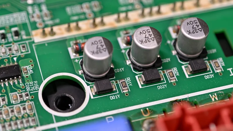
Close-up of rectifier diodes
Key Takeaways
A full-wave rectifier uses both the positive half cycle and the negative half cycle of the input, producing a smoother, higher-average DC output than a half-wave rectifier.
Two topologies dominate: the center-tapped full-wave rectifier (2 diodes plus a center-tapped transformer) and the full-wave bridge rectifier (4 diodes, no center tap required).
The average (DC) output voltage is Vdc = 2Vm/π ≈ 0.637 Vm, the ripple factor is 0.482, and the maximum rectification efficiency is 81.2%.
Ripple frequency is twice the line frequency (100 Hz on a 50 Hz supply, 120 Hz on a 60 Hz supply), which makes the pulsating DC easier and cheaper to filter with a capacitor.
Bridge rectifiers need diodes rated for only Vm of peak inverse voltage, while center-tapped designs require diodes rated for 2Vm.
Introduction
Electricity from the wall socket is AC. But most electronic devices need DC to work. A rectifier is a circuit that changes AC into DC. A half-wave rectifier can do this job, but it only uses half of the AC signal. This means the output is weak and not very smooth. A full-wave rectifier is better. It uses the full AC signal and gives a stronger and smoother DC output. Because of this, full-wave rectifiers are used in most real power supplies.
This article explains how the two main full-wave rectifier circuits work, derives the formulas you need for design, walks through filtering, and provides design tips that help engineers in practice.
What is a Full-wave Rectifier?
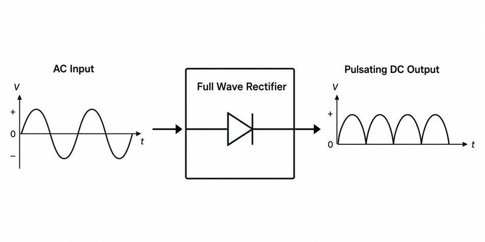
A full-wave rectifier is an electronic circuit that converts AC into pulsating DC by using both halves of the input waveform [1]. It is built using diodes. A diode allows current to flow in only one direction — it conducts when forward-biased and blocks current when reverse-biased.
Recommended Reading: Optimizing Diode Functionality: Forward and Reverse Bias
Instead of discarding the negative half cycle, the circuit redirects it. As a result, the output consists of a series of positive pulses at twice the frequency of the input. A capacitor or other filter then smoothes this pulsating DC into the steady direct current that electronic loads need.
Compared to a single rectifier diode used in a half-wave rectifier, a full-wave rectifier delivers more power to the load and makes better use of the transformer's capacity.
Full-Wave vs. Half-Wave Rectifier
A half-wave rectifier uses a single diode and conducts only during the positive half-cycle, so the output voltage exists for only half of each period [2]. The result is a low average DC voltage, a high ripple factor (1.21), and a ripple frequency equal to the line frequency [3].
Full-wave rectification fixes all three problems. By using both half cycles, it doubles the average output voltage, cuts the ripple factor to 0.482, and pushes the ripple frequency to 2f. The trade-off is more diodes and, in one topology, a more complex transformer.
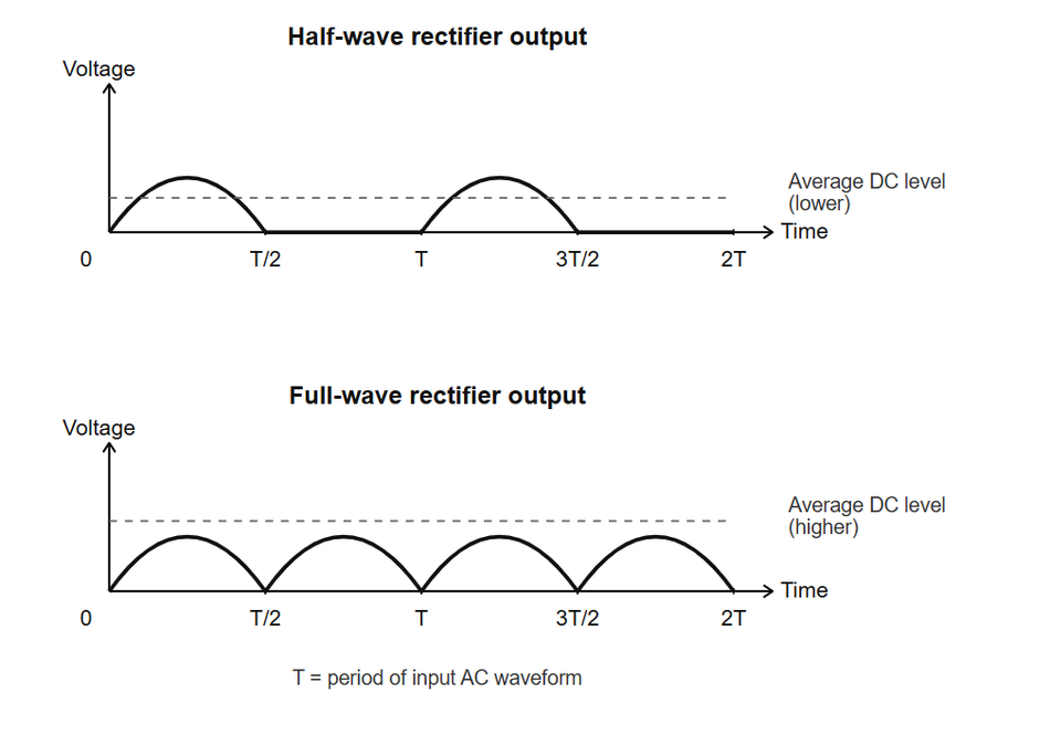
Waveforms of Half-wave rectifier & Full-wave rectifier.
A half-wave rectifier converts AC to DC with a maximum efficiency of only 40.6%, since half the input power is never used. A full-wave rectifier doubles this to 81.2%, as it makes use of the complete AC waveform. This is one of the main reasons full-wave rectifiers are preferred in real power supply designs, despite the extra diodes required.
How a Full-Wave Rectifier Works
The two standard implementations are the center-tapped full-wave rectifier and the full-wave bridge rectifier. Both produce the same output waveform; they differ in diode count, transformer requirements, and peak inverse voltage (PIV) — the maximum reverse voltage a diode must withstand without breaking down.
Center-Tapped Full-Wave Rectifier
A center-tapped full-wave rectifier uses a step-down transformer whose secondary winding has a connection at its electrical midpoint. This center tap is the circuit's DC reference (ground), splitting the secondary into two equal voltages that are 180° out of phase.
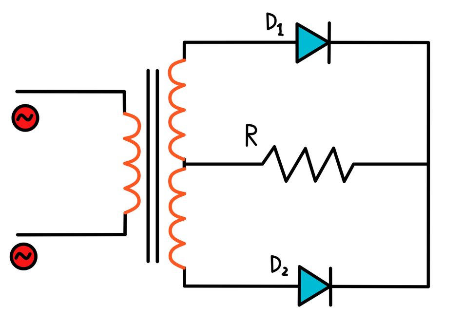
Full-wave Center-tapped rectifier circuit
Two diodes connect to the outer ends of the secondary winding, and the load resistor connects between the diode outputs and the center tap. During the positive half cycle, the upper diode is forward biased while the lower diode is reverse biased, so current flows from the top half of the winding through the load. During the negative half cycle, the roles reverse: the lower diode conducts and the upper diode blocks.
In both cases, current flows through the load resistor in the same direction, producing full-wave DC. Only one diode conducts at a time, so there is a single diode voltage drop (about 0.7 V for a silicon p–n junction diode) in the conduction path. The drawback is the peak inverse voltage: the non-conducting diode sees 2Vm across it, so each diode must be rated accordingly [4]. The center-tapped transformer is also bulkier and more expensive to wind.
Full-Wave Bridge Rectifier
The full-wave bridge rectifier, or Graetz circuit, uses four diodes in a bridge configuration and needs no center tap. The AC signal is applied across one diagonal of the bridge, and the load connects across the other diagonal.
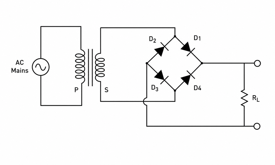
Full-wave bridge Rectifier circuit
During the positive half cycle, two diodes on opposite corners are forward biased and conduct in series, while the other two are reverse biased. During the negative half cycle, the other diode pair conducts. As with the center-tapped circuit, current always flows through the load resistor in the same direction.
The bridge topology has two big advantages. First, each diode only needs to withstand a peak inverse voltage of Vm, half that of the center-tapped design. Second, it uses a simpler transformer (or no transformer at all), giving a transformer utilization factor of 81.2% versus 69.3% for the center-tapped circuit. This difference exists because the bridge rectifier uses the entire secondary winding to conduct current during both half cycles, while the center-tapped design only uses half the winding at a time — so the transformer's copper is used less efficiently. The cost is two diode drops in the conduction path (about 1.4 V total), which matters in low-voltage applications. For a deeper walkthrough, see Wevolver's guide on how a bridge rectifier works.
Full Wave Rectifier Formulas and Derivations
The following relationships assume an ideal full-wave rectifier with peak secondary voltage Vm and a purely resistive load. They hold for both the center-tapped and bridge topologies.
Parameter | Formula | Value |
Average (DC) output voltage | Vdc = 2Vm/π | 0.637 Vm |
RMS output voltage | Vrms = Vm/√2 | 0.707 Vm |
DC load current | Idc = 2Im/π | 0.637 Im |
Ripple factor | γ = √((Vrms/Vdc)² − 1) | 0.482 |
Form factor | Vrms/Vdc | 1.11 |
Peak factor | Vm/Vrms | 1.414 |
Rectification efficiency (max) | η | 81.2% |
Ripple frequency | 2 × line frequency | 100/120 Hz |
Average (DC) Output Voltage
The average, or DC, output voltage is the mean value of the pulsating output over one cycle — this is the steady voltage a multimeter would read.
Vdc = 2Vm/π
For a full-wave rectifier: Vdc ≈ 0.637 Vm
RMS Output Voltage
The RMS (root mean square) output voltage represents the equivalent steady voltage that would deliver the same power to a resistive load.
Vrms = Vm/√2
For a full-wave rectifier: Vrms ≈ 0.707 Vm [7]
DC Load Current
The DC load current is the average current delivered to a resistive load, following directly from Vdc.
Idc = 2Im/π = Vdc/RL
For a full-wave rectifier: Idc ≈ 0.637 Im
Ripple Factor
The ripple factor measures how much AC ripple remains riding on the DC output relative to the DC value itself — lower is smoother.
γ = √((Vrms/Vdc)² − 1)
For a full-wave rectifier: γ ≈ 0.482 (before any capacitor filtering is added)
Form Factor
The form factor is the ratio of RMS to average output voltage, indicating how far the waveform deviates from pure DC.
Form Factor = Vrms/Vdc
For a full-wave rectifier: Form Factor ≈ 1.11
Peak Factor
The peak factor is the ratio of the peak output voltage to the RMS output voltage.
Peak Factor = Vm/Vrms
For a full-wave rectifier: Peak Factor ≈ 1.414 (√2)
Rectification Efficiency
Rectification efficiency is the ratio of DC output power delivered to the load to the total AC input power, expressed as a percentage.
η = (Pdc/Pac) × 100%
For a full-wave rectifier, η(max) = 81.2% — double the 40.6% ceiling of a half-wave rectifier.
Peak Inverse Voltage (PIV)
PIV is the maximum reverse voltage a non-conducting diode must withstand without breaking down.
Center-tapped: PIV = 2Vm
Bridge: PIV = Vm
For a full-wave rectifier, PIV is topology-dependent — always rate diodes at least 1.5× the calculated value to allow for line transients.
Ripple Voltage (with a filter capacitor)
Once a smoothing capacitor is added, ripple voltage depends on load current, capacitance, and ripple frequency rather than the unfiltered ripple factor above.
Vripple ≈ Idc / (2fC)
For a full-wave rectifier, the ripple frequency is 2f, so the required capacitance is about half that of a half-wave design for the same ripple.
Filtering: Turning Pulsating DC into Smooth DC
The raw output of a full-wave rectifier is pulsating DC, not the clean DC voltage that most electronic circuits require. A filter stage removes the ripple.
The most common choice is a capacitor-input (shunt capacitor) filter. The capacitor charges to the peak voltage and then discharges into the load between peaks, filling in the valleys of the waveform. For a capacitor C feeding a DC load current Idc, the peak-to-peak ripple voltage is approximately:
Vripple ≈ Idc /(2 f C)
The factor of 2f (not f) is a direct benefit of full-wave rectification: because the ripple frequency is doubled, you need only about half the capacitance of a half-wave design for the same ripple. Larger capacitors reduce ripple but increase the diode surge current at turn-on, so there is a trade-off.
For demanding loads, designers add inductors (choke-input or LC filters) to further attenuate ripple, or follow the filter with a voltage regulator to hold the DC output constant despite line and load variation. Where conversion losses matter, modern designs replace diodes with MOSFET-based synchronous rectification to cut the forward voltage drop and use Schottky or SiC devices for high-frequency, high-efficiency converters.
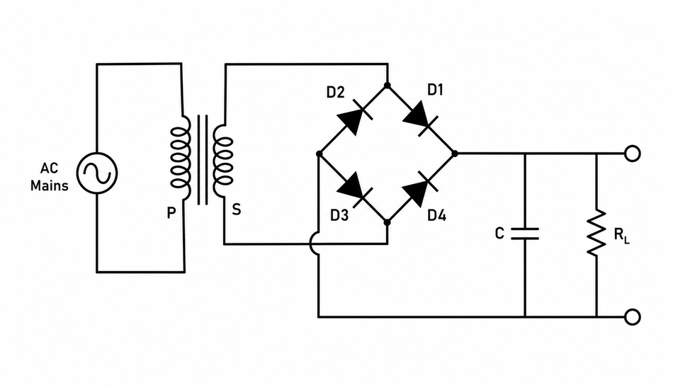
Full-wave center-tapped rectifier with capacitor filter.
Topology Comparison
Criterion | Half-Wave | Center-Tapped Full Wave | Bridge Full Wave |
Number of diodes | 1 | 2 | 4 |
Transformer | Optional | Center-tapped (required) | Simple/optional |
Peak inverse voltage | Vm | 2Vm | Vm |
Diode drops in the path | 1 | 1 | 2 |
Ripple factor | 1.21 | 0.482 | 0.482 |
Ripple frequency | f | 2f | 2f |
Max efficiency | 40.6% | 81.2% | 81.2% |
Transformer utilization factor | 0.287 | 0.693 | 0.812 |
Use the center-tapped circuit when you need a single-diode drop in the path (low-voltage, high-current outputs) and a center-tapped transformer is already available. Choose the bridge when you want the lowest PIV rating, the best transformer utilization, or a transformerless design.
Design Considerations and Common Mistakes
Diode current and surge ratings. Size the average forward current for Idc and check the repetitive surge current, which spikes as the smoothing capacitor charges. Undersized diodes fail on the first power-up.
PIV margin. A diode rated exactly at the calculated PIV will eventually fail from line transients. Apply at least a 1.5× margin.
Capacitor selection. Match the capacitor's voltage rating to the peak output and its ripple-current rating to the load; electrolytic capacitors degrade if the ripple current is exceeded.
Thermal management. Two conducting diodes in a bridge dissipate roughly 1.4 V × Idc as heat. At several amps, an integrated bridge rectifier package needs a heatsink.
Confusing topologies. Wiring a bridge with a center-tapped transformer, or grounding the wrong node in a center-tapped circuit, is a frequent error that produces a half-wave or shorted output.
Applications of Full-Wave Rectifiers
Full-wave rectifiers are used anywhere AC must become DC. Common applications include:
Power supplies — Linear and switch-mode DC power supplies rely on full-wave rectification as the first conversion stage after the transformer or input filter. This makes it the entry point for nearly every consumer electronic device, from laptop chargers to televisions.
Battery charging — Chargers for phones, laptops, EVs, and industrial battery banks all need a stable DC source to control charge current and voltage safely. Full-wave rectification provides the low-ripple base voltage that charging circuits then regulate more precisely.
Motor control — DC motor drives use rectified AC to supply the armature or field windings with controllable DC voltage. This is common in variable-speed drives, where the rectified DC is further processed by a chopper or inverter stage.
Industrial processes — Welding equipment needs high-current, low-ripple DC to maintain a stable arc, while electroplating requires steady DC to ensure uniform metal deposition. Both processes are sensitive to ripple, making full-wave designs the practical minimum.
Renewable energy — Solar/PV inverter systems often use rectification as part of an AC-DC-AC conversion chain, particularly in grid-tied and hybrid inverter designs. This allows power to be conditioned, stored, or converted before being fed back to the grid or load.
Telecom infrastructure — Telecom equipment typically runs on rectified DC bus voltages (commonly -48V DC) for reliability and battery backup compatibility. Full-wave rectifiers convert incoming AC mains into the standard DC bus at the power plant stage.
Integrated bridge rectifier modules make the bridge topology the default choice for most line-powered equipment, since they offer four diodes in a single compact package. Meanwhile, three-phase full-wave bridges dominate industrial drives and HVDC transmission, where higher power levels and lower ripple are essential.
Suggested Reading: Linear vs Switching Power Supply: Understanding the Differences
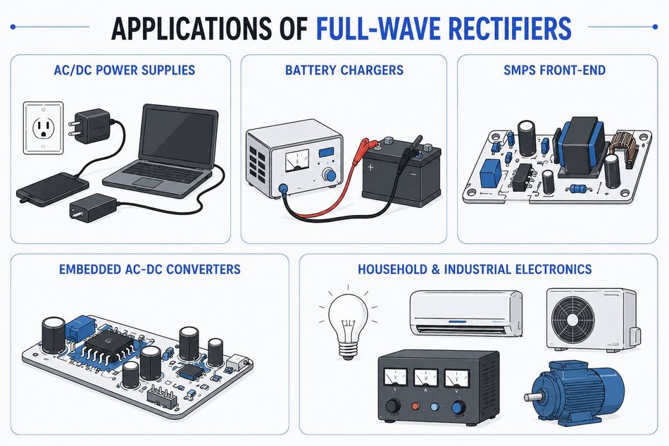
Applications of the Full-wave Rectifier
Conclusion
A full-wave rectifier is the workhorse that turns alternating current into usable direct current with a 0.637 Vm average output, a 0.482 ripple factor, and up to 81.2% efficiency. Choosing between the center-tapped and bridge topologies comes down to PIV rating, transformer cost, and how many diode drops your voltage budget can absorb. Pair the rectifier with a correctly sized capacitor — taking advantage of the doubled ripple frequency — and a regulator, and you have a clean, reliable DC supply.
Frequently Asked Questions
What is the main advantage of a full-wave rectifier over a half-wave rectifier?
A full-wave rectifier uses both half cycles of the AC input, so it delivers roughly double the average DC output voltage, a much lower ripple factor (0.482 vs 1.21), double the ripple frequency for easier filtering, and up to 81.2% efficiency versus 40.6%.
Why does a bridge rectifier need four diodes?
The four diodes form two conduction pairs. One pair conducts during the positive half cycle and the other during the negative half cycle, steering current through the load in the same direction both times — without needing a center-tapped transformer.
What is the peak inverse voltage of a full-wave rectifier?
Peak inverse voltage (PIV) is the maximum reverse voltage a diode must withstand without breaking down. In a full-wave rectifier, it depends on the topology: Vm for a bridge rectifier, and 2Vm for a center-tapped rectifier. This is why bridge rectifiers are preferred at higher voltages.
What is the ripple frequency of a full-wave rectifier?
Ripple frequency is the rate at which the pulsating DC output of a rectifier rises and falls. For a full-wave rectifier, it is twice the input line frequency — 100 Hz on a 50 Hz supply, 120 Hz on a 60 Hz supply.
How do you calculate the DC output voltage of a full-wave rectifier?
The DC output voltage is the average voltage delivered to the load. For an ideal full-wave rectifier, Vdc = 2Vm/π ≈ 0.637 Vm, where Vm is the peak secondary voltage. In practice, subtract diode drops (~0.7 V each) and resistive losses for the real-world value.
Which is better, a center-tapped or a bridge full-wave rectifier?
The bridge rectifier is better for most applications because of its lower PIV requirement and higher transformer utilization factor (81.2% vs 69.3%). The center-tapped design wins only when a single diode drop is critical, and a center-tapped transformer is already available.
References
[1] W. Storr, "Full Wave Rectifier and Bridge Rectifier Theory," Electronics Tutorials. [Online]. Available: https://www.electronics-tutorials.ws/diode/diode_6.html
[2] "Rectifier," Wikipedia, The Free Encyclopedia. [Online]. Available: https://en.wikipedia.org/wiki/Rectifier
[3] "Full Wave Rectifier: What is it? (Circuit Diagram and Formula)," Electrical4U. [Online]. Available: https://www.electrical4u.com/full-wave-rectifiers/
[4] R. Nave, "Center-tap Full-wave Rectifier," HyperPhysics, Dept. of Physics and Astronomy, Georgia State Univ. [Online]. Available: http://hyperphysics.phy-astr.gsu.edu/hbase/Electronic/rectct.html
[5] "Full Wave Rectification — Theory," IIT Kharagpur Virtual Labs. [Online]. Available: https://be-iitkgp.vlabs.ac.in/exp/full-wave-rectification/theory.html
[6] "Peak inverse voltage," Wikipedia, The Free Encyclopedia. [Online]. Available: https://en.wikipedia.org/wiki/Peak_inverse_voltage
[7] "Full Wave Rectifier — Definition, Formulas, Working and Construction," GeeksforGeeks. [Online]. Available: https://www.geeksforgeeks.org/physics/full-wave-rectifier/
in this article
1. Key Takeaways2. Introduction3. What is a Full-wave Rectifier?Full-Wave vs. Half-Wave Rectifier5. How a Full-Wave Rectifier Works6. Full Wave Rectifier Formulas and Derivations7. Filtering: Turning Pulsating DC into Smooth DC8. Topology Comparison9. Design Considerations and Common Mistakes10. Applications of Full-Wave Rectifiers11. Conclusion12. Frequently Asked Questions