Fillet vs Chamfer: A Comprehensive Technical Guide for Engineers
Understanding the key differences, applications, and selection criteria for fillets and chamfers in digital design, hardware, and electronics engineering.

30 May, 2025. 17 minutes read
Key Takeaways
Fillets have rounded edges, and they excel at reducing stress concentrationsenhancing the durability and fatigue life of components, making them crucial for load-bearing applications.
Chamfers, featuring angled or sloped edges, are more cost-effective and faster to manufacture, particularly through manual processes.
The selection between a fillet versus a chamfer depends on factors such as stress requirements, the chosen manufacturing process, cost constraints, assembly needs, safety considerations, and the desired aesthetic outcome.
Applications for these features are diverse, spanning mechanical hardware, electronics, and even digital design.
Introduction
In engineering design, sharp edges and corners on components often present significant challenges. They can complicate manufacturing processes, hinder assembly, pose safety hazards during handling, and, critically, act as points of stress concentration that compromise structural integrity. Addressing these sharp transitions effectively is a fundamental aspect of robust design across mechanical, electronic, and even digital domains.
Fillets and chamfers are applied as the two primary methods to treat edges and corners.
A fillet introduces a rounded transition
Chamfer creates an angled or sloped edge.
While seemingly simple geometric modifications, the choice between a fillet vs chamfer carries significant implications for a part's performance, manufacturability, cost, and safety. This article provides a comprehensive technical comparison of fillet vs chamfer, targeting engineers and technical professionals in digital design.
What are Fillets and Chamfers in Engineering
Understanding the fundamental geometric differences and intended purposes of fillets and chamfers is the first step towards their effective application.
What is a Fillet? (Geometry and Types)
A fillet is defined as a rounding of an interior or exterior corner of a part. It creates a smooth, curved transition between two intersecting surfaces, replacing a sharp corner with an arc.
Geometrically, a fillet is characterized by its radius (R), which defines the size of the curve. Fillets are typically tangent to the surfaces they connect, ensuring a smooth blend. They can be applied to both interior and exterior corners:
Interior Fillets: These occur at inside corners, forming a concave surface (like the inside corner of a box).
Exterior Fillets (often called Rounds): These occur at outside corners, forming a convex surface (like the outer edge of a cylinder or table).
The primary purpose of a fillet is to reduce stress concentration. However, they also improve the aesthetic appearance of a part by softening sharp lines, which can sometimes aid in manufacturing. For instance, it can improve material flow in casting or molding processes or allow the use of specific cutting tools.
It is important to note a common point of terminological inconsistency. Strictly speaking, "fillet" often refers to the rounding of an internal corner, while "round" refers to the rounding of an external corner. However, many engineers and CAD systems use the term "fillet" to describe both internal (concave) and external (convex) rounded edges.
What is a Chamfer? (Geometry, Common Angles)
A chamfer is a transitional edge created between two intersecting faces of an object, forming a flat, sloped, or angled surface, often referred to as a bevel. Unlike the curved transition of a fillet, a chamfer is linear.
Geometrically, chamfers are frequently created at a 45° angle between two surfaces that meet at a right angle (90°). However, chamfers can be created at various other angles depending on the application requirements. They are typically specified by: *
Two distances (e.g., distance along each adjacent face from the theoretical sharp corner)
A distance and an angle
A single length designation 'C' implying a 45° angle.
The primary purposes of incorporating chamfers include:
Breaking Sharp Edges: To improve safety, ease handling, and prevent injury or damage caused by sharp corners.
Facilitating Assembly: To provide a lead-in for inserting fasteners (like screws or bolts) into holes or for guiding mating parts together.
Deburring: To remove small, sharp projections (burrs) left after machining operations.
Aesthetics: To provide a specific visual style, often perceived as clean, technical, or precise.
Similar to the fillet/round distinction, the terms "chamfer" and "bevel" can sometimes be confusing. While often used interchangeably, some sources differentiate them, suggesting a bevel might be a slope between parallel surfaces or any non-45° angled edge, while a chamfer is specifically the edge break, often assumed to be 45° unless otherwise specified.
Theoretical Impact: Stress Concentration Analysis
Stress distribution is one of the most critical factors when it comes to the functional differences between fillets and chamfers.
The Concept of Stress Concentration (Kt)
Stress concentration refers to the phenomenon where stress levels within a material become significantly higher in localized areas compared to the average stress across the component.
The magnitude of this effect is called the Stress Concentration Factor (Kt), defined as the ratio of the maximum local stress (σ_max) at the discontinuity to the nominal or average stress (σ_nom) in the surrounding area:
Kt = σ_max / σ_nom
A Kt value greater than 1 indicates the presence of stress concentration. The value of Kt is dimensionless and depends heavily on the specific geometry of the discontinuity and the type of loading applied.
High stress concentrations are a major concern in engineering design because they can lead to premature component failure, particularly under fatigue loading (repeated stress cycles).
How Fillets Mitigate Stress Concentration
Since fillets provide a smooth, curved transition, they are highly effective at reducing stress concentrations. It allows stress flow lines within the material to gradually change direction. Hence, it distributes the stress over a significantly larger area compared to a sharp corner. As a result, it dramatically reduces the peak stress (σ_max) experienced at the corner.
Effect on Kt: The fillet radius directly affects the Stress Concentration Factor. A larger fillet radius leads to a lower stress concentration factor (Kt) and thus a lower peak stress. Therefore, in designs where components are subjected to significant loads or cyclic stresses, maximizing the fillet radius in critical areas is a key strategy for enhancing structural integrity.
Stress Concentration in Chamfered Edges
Chamfers also serve to break sharp corners, reducing stress concentration compared to a perfectly sharp, zero-radius corner. However, the angled transition still represents a relatively abrupt change in geometry for stress flow lines. Stress tends to concentrate at the two edges where the chamfered flat meets the original surfaces.
Compared to a fillet of similar size designed for stress reduction, a chamfer is significantly less effective at distributing stress. Instead of smoothly spreading the stress over a wide curve, a chamfer tends to redirect or concentrate the stress into smaller areas near its edges.
This makes chamfers generally unsuitable for applications involving high static loads or significant fatigue cycles where stress concentration is a primary failure concern. Using a chamfer in such situations can lead to localized yielding, deformation, or crack initiation under loads that a properly filleted component could withstand.
Comparing Stress Flow: Fillets vs. Chamfers
Visualizing the path of stress through a material helps illustrate the difference. Stress flow lines, analogous to fluid streamlines, prefer smooth, gradual paths.
Fillet | Chamfer |
|
|
This inherent geometric difference makes fillets the superior choice when minimizing stress concentration is the primary design objective.
Manufacturing Methods and Considerations
The choice between fillets and chamfers is also heavily influenced by how they are produced. Different manufacturing processes have varying capabilities, costs, and complexities associated with creating these features. Depending on the type of material, the following processes are used for chamfer and fillet manufacturing.
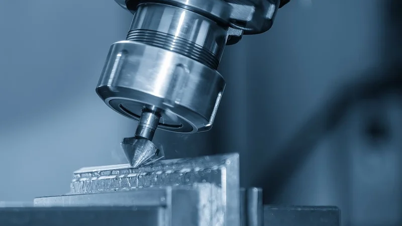
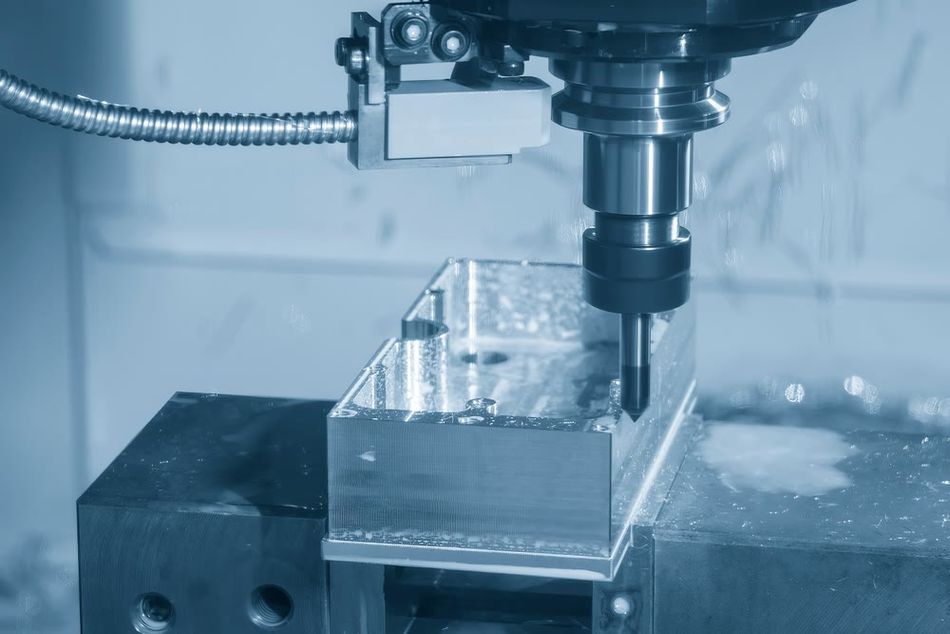
CNC Machining: Use of rotating cutting tools to remove material
Injection Molding: Injecting molten material into a die or mold
Casting: Pouring molten metal into a mold
3D Printing: Layer by layer creation of fillets or chamfers.
Creating Fillets and Chamfers: Common Processes
The following table summarizes various manufacturing practices for chamfers and fillets.
Technique | Fillet | Chamfer |
CNC Milling | Created using end mills. External fillets might use corner-rounding end mills with a specific radius. Internal fillets or more complex curves often require ball-nose end mills. Achieving a smooth, accurate fillet requires careful toolpath programming. | Created using specifically angled tools like chamfer mills, countersinks, or spot drills. A single tool can often produce chamfers of different sizes by varying the cutting depth. |
Highly molten material, typically plastic or metal is injected into a die or mold with a predefined shape of a fillet. | The process is similar to that of a fillet except for the shape of the mold. | |
Casting | Similar to molding, but the material is typically molten metal. The process is well suited to prevent cracks and voids as molten material fills up and gaps. | |
3D Printing | Can be readily printed, but the curved overhangs, especially on surfaces not parallel to the build plate, might require support structures, potentially impacting surface finish and increasing post-processing time. Fillets can still be used to strengthen internal corners where layers meet. | Often print more easily than fillets when oriented along the Z-axis (build direction). A consistent 45° chamfer, for example, typically represents a manageable overhang angle for many 3D printing processes without requiring extensive support. |
Suggested Reading: 3D Printing in Defense: Applications and Benefits
Manufacturing Complexity, Cost, and Time Trade-offs
As a rule of thumb, chamfers are generally less complex, faster, and cheaper to manufacture than fillets. It’s particularly true for manual machining operations or basic CNC work where simpler tooling and cutting paths for chamfers translate directly to lower time and cost.
Fillets often bring complexity due to the need for specific radius tools, more intricate toolpath programming. It extends setup times, and leads to increased machining time.
However, this "chamfers are cheaper" guideline is an oversimplification and highly dependent on the context:
CNC Machining: With modern, automated CNC machines, the time difference between cutting a simple fillet and a chamfer might be negligible, especially if tool changes are quick. The programming complexity for a fillet might still be slightly higher, but the actual machine time difference may not be significant in all cases. Using standard fillet radius tools can help mitigate costs.
Molding & Casting: Fillets are frequently required for good manufacturability. Sharp internal corners are difficult and expensive to create in tooling, prone to wear, impede material flow, and can cause part defects. Adding fillets simplifies the molding/casting process itself, improves yield, and reduces tooling maintenance, often resulting in a lower overall cost and higher quality part.
Production Volume: The cost impact of adding either feature is generally more pronounced in low-volume production runs, where setup and programming costs are amortized over fewer parts.
Suggested Reading: How Fillets and Chamfers Impact CNC Machining Costs
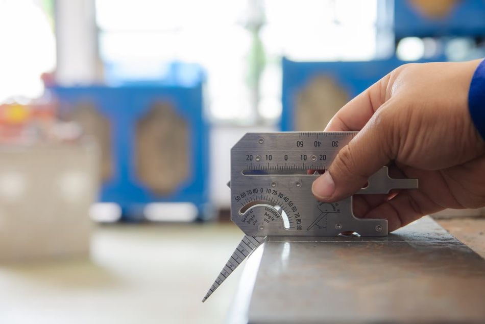
Achievable Tolerances and Relevant Standards
Maintaining dimensional accuracy is crucial for both fillets and chamfers, but achieving tight tolerances invariably increases manufacturing cost and complexity.
CNC Machining: General tolerances for CNC-machined features often start around ±0.1 mm. ISO 2768 is an international standard simplifying technical drawings by providing general tolerances for linear and angular dimensions when specific values are absent. Part 1 defines tolerance classes (fine to very coarse), and crucially, Table 2 specifies permissible deviations for fillet radii and chamfer heights based on their nominal size (e.g., ±0.2mm for 0.5-3mm). Part 2 defines classes for geometrical tolerances, and a common specification combines both (e.g., ISO 2768-mK).
Injection Molding: Tolerances are highly dependent on the specific plastic material (due to varying shrinkage rates), part size and geometry, feature type, and the quality/precision of the mold itself. PLASTICS (formerly SPI) offers guidelines for injection molding tolerances, categorizing them as lower-cost 'Commercial' or higher-cost 'Fine/Precision'. Tables detail typical tolerance ranges for various plastics and features based on size. Generally, ±0.5mm is common, with ±0.125mm achievable at higher expense. Fillet design often relates to wall thickness to ensure uniformity and prevent defects.
Die Casting: Tolerances are influenced by the specific metal alloy, die complexity, part size, and factors related to the die construction, such as the parting line location and the use of moving die components (MDCs). The North American Die Casting Association (NADCA) sets widely used standards that differentiate between 'Standard' tolerances, suitable for most applications, and 'Precision' tolerances, offering tighter control for critical features at a higher cost and requiring more die maintenance. These standards cover aspects like linear dimensions, parting line variation, and draft angles. NADCA recommends fillets and radii to ensure smooth metal flow and minimize stress, often suggesting a minimum radius (e.g., 0.4mm) and relating internal radii to wall thickness. Draft angles, tapers on vertical walls, are crucial for damage-free part ejection, with the required angle depending on depth, surface type, and the alloy used.
Suggested Reading: Design Tips for Die Casting
Practical Applications Across Engineering Disciplines
Fillets and chamfers find widespread use across various engineering fields, extending even into the digital realm, although their primary functions and importance can vary significantly depending on the context.
Hardware Engineering: Mechanical Components, Enclosures, and Thermal Management
In traditional hardware engineering, the choice between fillet and chamfer is often driven by a combination of mechanical function, manufacturability, and safety.
Mechanical Components (Gears, Shafts, Structures):
Fillets: Are critical in load-bearing components where stress concentrations can lead to failure. They are used at transitions like shaft steps, roots of gear teeth, and inside corners of brackets to significantly increase strength, durability, and fatigue life by distributing stress.
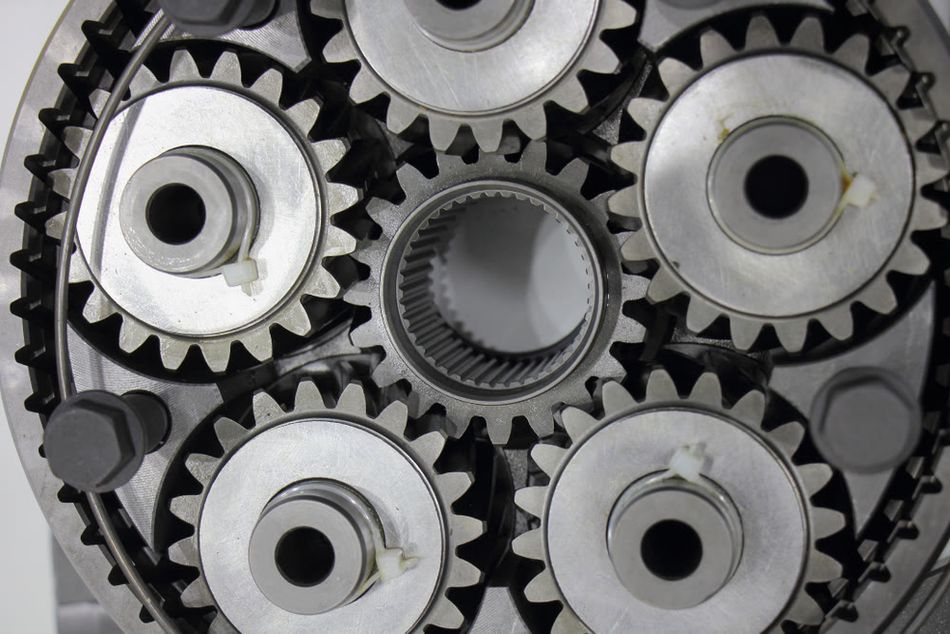
Chamfers: Are commonly used to provide lead-ins on shafts, pins, or bolt holes to facilitate easier assembly into mating parts. They are also used for breaking sharp edges for safe handling or sometimes for specific functional reasons, like modifying gear tooth tips to prevent damage during heat treatment or meshing.
Enclosures (Sheet Metal, Plastic):
Fillets: Can enhance aesthetics by providing a softer, more finished look. Rounded edges improve ergonomics and safety, especially for enclosures that are handled. In molded plastic enclosures, fillets are often essential for manufacturability, aiding material flow and part ejection.
Chamfers: Provide a simple way to break sharp edges on metal or plastic enclosures for safety and handling. They can contribute to a modern or technical aesthetic. In sheet metal fabrication, simple chamfers might be easier or cheaper to implement than forming a radius for basic edge breaking. Chamfers also aid in the assembly of multi-part enclosures.
Thermal Management (Heat Sinks):
Fillets: While the primary focus in heat sink design is often on fin geometry, spacing, and material, smooth transitions provided by fillets or radii on fins or at the base could potentially improve airflow characteristics. Reducing sharp edges might minimize flow separation and turbulence, potentially lowering pressure drop and enhancing convective heat transfer compared to sharp-edged designs.
Chamfers: Are less likely to be a primary feature for enhancing thermal performance via fluid dynamics. They might be used on mounting features or the heat sink base for assembly or safety reasons.
CFD Analysis: Computational Fluid Dynamics (CFD) plays a crucial role in optimizing heat sink performance. CFD simulations model fluid flow (usually air) and heat transfer, allowing engineers to analyze the impact of various geometric features, including fin shapes, spacing, and potentially edge treatments, on thermal resistance and pressure drop.
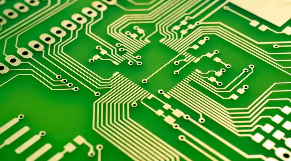
Electronics Engineering: PCB Design Considerations
Within electronics engineering, particularly in Printed Circuit Board (PCB) design, fillets and chamfers take on specific roles related to connectivity, signal integrity, and manufacturability.
PCB Edge Connectors (e.g., PCI, Card Edge):
Chamfering: It is essential for PCBs designed to plug into edge connectors. A chamfer (often called a bevel, especially if not 45°) is machined onto the leading edge of the PCB's contact fingers. This angled lead-in allows the board to be inserted smoothly and correctly into the female connector socket on a motherboard or backplane, preventing damage to both the board contacts and the connector. Specific standards dictate the required chamfer angle (e.g., 20° for PCI, 45° for older PC cards) and depth (e.g., 0.5mm).
PCB Trace Routing:
- Chamfering (45° Corners): It has long been standard practice to route high-speed signal traces using 45° angled turns instead of sharp 90° corners. The historical rationale was to improve signal integrity by reducing reflections and controlling impedance discontinuities caused by the abrupt change in direction. However, modern analysis indicates that for most typical digital signal frequencies and rise times, the signal integrity benefit of 45° turns over 90° turns is often negligible.
The primary practical benefit of using 45° turns ("chamfered" corners) in routing today is routing density and efficiency. A 45° turn takes up less space and results in a shorter overall trace length compared to a 90° turn covering the same X-Y distance. This is particularly advantageous on densely populated boards. It also helps avoid creating large inductive loops, which can contribute to electromagnetic interference (EMI). Most PCB layout software encourages or defaults to 45° routing modes.
Filleting (Rounded Corners/Arcs): Using smooth arcs instead of angled corners is another option for routing, particularly relevant in microwave or RF designs where precise impedance control is critical. Smooth curves can potentially offer better impedance matching than angled turns. PCB design tools often provide corner modes that allow for the placement of arcs during interactive routing.
PCB Outline/Edge Finishing:
Fillets: The overall shape of the PCB can incorporate rounded corners (fillets). This might be for aesthetic reasons, or more commonly, to fit the PCB within an enclosure that has rounded internal corners. These are typically defined by placing arcs as part of the board outline definition layer.
Chamfers: Similar to mechanical parts, chamfers can be applied to the external corners of the PCB outline for aesthetic purposes or to break sharp corners for safer handling.
Edge Plating: This involves plating the vertical edges of the PCB with metal, connecting the top, bottom, and internal copper layers. Its benefits include improved electromagnetic compatibility (EMC) by shielding radiating edges, enhanced signal and power integrity through better grounding, improved thermal dissipation by conducting heat to the edge, and increased structural rigidity.
Component Clearances & DFM:
Standard PCB DFM guidelines dictate minimum clearances between various features like traces, pads, vias, and the physical edge of the board. Any edge treatments like chamfers or fillets on the board outline must respect these clearances.
For mounting holes, countersinks or chamfers are often used. These allow the heads of flat-head screws to sit flush with or below the PCB surface. This is crucial for saving vertical space in compact designs (like smartphones) and improving mechanical stability by preventing screw heads from snagging or interfering with other components.
Suggested Reading: Design for Manufacturing (DFM): The Ultimate Guide to Streamlining Product Development and Reducing Costs
Functional Comparison: Head-to-Head Analysis
To solidify the understanding of when to use each feature, a direct comparison across key functional criteria is helpful.
Ease of Assembly and Mating Parts
Chamfers excel in assembly by providing angled lead-in surfaces that guide fasteners and align mating parts, reducing damage and increasing efficiency. Fillets, with their curved surfaces, can hinder fastener insertion and are not typically chosen for assembly facilitation.
Wear Resistance and Structural Durability
Fillets offer superior durability under load and stress due to better stress distribution, increasing fatigue strength. Chamfers provide some improvement over sharp corners but are less effective at mitigating stress and can be wear initiation points.
Safety, Handling, and Ergonomics
Fillets provide the highest safety and comfort by eliminating sharp edges with smooth, rounded surfaces, preferred for handheld devices and frequent human interaction. Chamfers break sharp edges, but still present angled edges that can feel sharp and snag.
Impact on Fluid Dynamics
Fillets are preferred for fluid flow applications, promoting laminar flow and reducing turbulence compared to the abrupt angled transition of chamfers.
Aesthetics and Product Appearance
Fillets typically offer a softer, more organic appearance favored in consumer products. Chamfers provide a cleaner, sharper, more technical aesthetic.
Coating Adherence and Corrosion Prevention
Fillets provide a superior surface for even and thick coating adherence, offering better corrosion protection. Coatings tend to thin on the sharp edges of chamfers, making them more susceptible to damage and corrosion.
Suggested Reading: Powder Coating vs. Anodizing for Aluminium
The following table summarizes the functional comparison between fillet and chamfer.
Feature Criterion | Fillet | Chamfer |
Stress Relief | Excellent (Distributes stress over larger radius) | Poor to Fair (Less effective than fillet; concentrates stress) |
Manufacturing Cost (Machining) | Generally Higher (More complex tools/paths) | Generally Lower (Simpler tools/cuts) \ |
Manufacturing Cost (Molding/Casting) | Often Lower/Required (Improves flow, ejection) | Can be simpler in tool, but less functional benefit |
Manufacturing Time (Manual) | Generally Longer | Generally Shorter |
Tooling Complexity | Higher (Specific radius tools needed) | Lower (Versatile tools often suffice) |
Ease of Assembly | Poor (Can hinder fastener insertion) | Excellent (Provides lead-in, aids alignment) |
Safety / Ergonomics | Excellent (Smooth, rounded, comfortable) | Fair (Breaks sharp edge, but still angled) |
Fluid Flow | Good (Smoother flow, less turbulence) | Poor (Induces more turbulence) |
Aesthetics | Soft, Organic, Smooth, Finished Look | Sharp, Angular, Technical Look |
Coating Adherence | Good (Uniform coverage) | Poor (Thinning at edges, prone to corrosion) |
Implementation in Common CAD Software
Modern CAD systems provide powerful and user-friendly tools for creating both fillets and chamfers. Understanding how to access and utilize these tools effectively is essential for translating design intent into manufacturable geometry.
Overview of Fillet/Chamfer Tools
Fillet and Chamfer commands are fundamental modeling features found in virtually all parametric 3D CAD software used by engineers and designers, including:
SolidWorks
AutoCAD
Autodesk Fusion 360
Altium Designer for PCB layout.
The general workflow for applying these features is typically consistent across platforms:
Activate the respective Fillet or Chamfer command, usually found in a 'Features' or 'Modify' toolbar or menu.
Select the geometric entities to which the feature should be applied (e.g., edges, faces, vertices, or entire features).
Specify the parameters defining the feature's size and shape (e.g., radius for a fillet; distances or distance and angle for a chamfer) via a dedicated dialog box, PropertyManager, or command-line prompts.
Preview the result and confirm the feature creation.
CAD tools significantly simplify the geometric creation of fillets and chamfers, often reducing complex operations to a few clicks. But the power of these tools is fully realized only when wielded with an informed understanding of the functional and practical implications discussed throughout this article.
Suggested Reading: Design custom 3D printed fixtures in under 20 minutes without CAD complexity
Conclusion
The choice between a fillet and a chamfer represents a core engineering design principle: balancing competing demands. This article has examined their critical differences beyond basic definitions, analyzing their impact on structural integrity, manufacturability, assembly, safety, and aesthetics. Fillets, with their smooth curves, excel at reducing stress concentrations, enhancing durability, and offering superior aesthetics, ergonomics, fluid flow, and coating adherence. Chamfers, with their angled surfaces, are advantageous for assembly, simpler and often cheaper to produce, and effectively break sharp edges for basic safety.
The selection of a fillet versus a chamfer is a context-driven decision requiring careful consideration of applied stresses, manufacturing processes, budget and time constraints, assembly needs, safety and ergonomics, desired aesthetics, and specific industry standards. As designs and manufacturing evolve, a deep understanding of these fundamental edge treatments remains vital for engineers to create robust, manufacturable, cost-effective, safe, and fit-for-purpose products by consciously evaluating the presented trade-offs.
Frequently Asked Questions (FAQ)
1. What is the main difference between a fillet and a chamfer?
The primary difference is their shape and typical primary purpose. A fillet is a rounded edge or corner, primarily used to reduce stress concentration and improve durability. A chamfer is an angled or sloped edge, primarily used to aid assembly (like providing a lead-in for screws) or simply to break a sharp edge for safety and handling.
2. Which is better for reducing stress concentration?
A fillet is significantly better for reducing stress concentration. Its smooth, curved shape allows stress to flow more gradually over a larger area, reducing the peak stress at the corner. Chamfers, while better than sharp corners, still introduce angled transitions where stress can concentrate more than in a well-designed fillet.
3. Are chamfers always cheaper to manufacture than fillets?
Not necessarily. While chamfers are often cheaper and faster in manual machining or simple CNC operations due to simpler tooling and cuts, the cost difference can become minimal in highly automated CNC environments. Furthermore, in molding and casting, fillets are often required for good material flow and part ejection, making them essential for manufacturability and potentially reducing overall cost despite adding geometric complexity.
4. When should I use a chamfer on a hole?
You should use a chamfer on a hole when it is intended for the insertion of fasteners like screws, bolts, or pins. The chamfer acts as a crucial lead-in, guiding the fastener and making insertion much easier while preventing damage to threads or the hole edge.
5. How does fillet radius size impact stress concentration?
Generally, a larger fillet radius results in lower stress concentration. The larger radius provides a more gradual transition for stress flow, distributing the stress more effectively and reducing the peak stress value (lower Kt).
References
How Fillets and Chamfers Impact CNC Machining Costs | Xometry Pro,
Fillets vs Chamfers: How to Handle Edges and Corners in Machining
Understanding the Difference Between a Fillet and Chamfer - RapidDirect
Chamfer or Fillet: It's More Than a Coin Toss - Engineering.com
Fillet vs. Chamfer — What Are the Differences and Uses? - Xometry
Fillets vs. Chamfers: A Comprehensive Guide - China VMT - CNC machining,
Fillet and Chamfer: What Are the Differences and Uses? - Zhongde
Fillet vs Chamfer: A Complete Guide for Applications - WayKen
Exploring Fillets and Chamfers: The Subtle Differences in Machining | Blog| HK OPRO Co.ltd
The Fillet Vs. Chamfer: A Detailed Comparison and Differences - KDM Fabrication
Considerations To Choose Between Fillets And Chamfers | JIAHUI BLOG
Engineering Drawing: Comparing Fillet and Chamfer Die Casting Design Guidelines - Premium Parts
in this article
1. Key Takeaways2. Introduction3. What are Fillets and Chamfers in Engineering4. Theoretical Impact: Stress Concentration Analysis5. Manufacturing Methods and Considerations6. Practical Applications Across Engineering Disciplines7. Functional Comparison: Head-to-Head Analysis8. Implementation in Common CAD Software9. Conclusion10. Frequently Asked Questions (FAQ)11. References