Active Bandpass Filter Design Guide
A bandpass filter is a circuit that allows a selected range of frequencies to pass while reducing low and high frequencies. This article covers the design of active bandpass filters using op-amps, resistors, and capacitors, including cutoff and center frequencies,, Sallen-Key and MFB topologies.

29 May, 2026. 15 minutes read
Key Takeaways
An active bandpass filter allows a selected frequency range to pass while attenuating both low- and high-frequency signals, making it essential for signal conditioning and noise reduction.
Unlike passive filters, active bandpass filters use operational amplifiers (op-amps) with resistors and capacitors, enabling signal gain, improved impedance matching, and better control of frequency response.
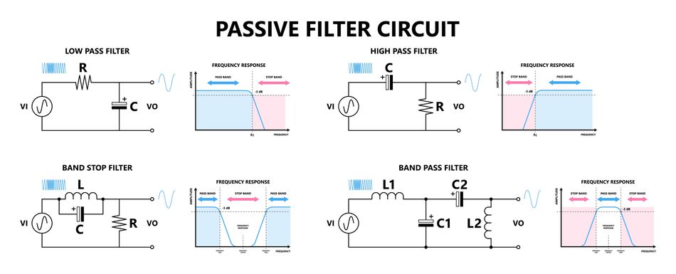
Bandpass behavior can be understood as a combination of a high-pass filter and a low-pass filter, forming a defined frequency window characterized by center frequency and bandwidth.
The performance of active bandpass filters is strongly influenced by the op-amp’s gain-bandwidth product, slew rate, and open-loop gain, which limit high-frequency accuracy.
For wide bandwidth applications, cascading separate high-pass and low-pass filters is a simple and effective design approach that avoids complex second-order structures.
For narrow-band applications, second-order topologies such as Multiple Feedback (MFB) and Sallen-Key bandpass filters provide better selectivity and frequency control.
MFB filters offer strong control over center frequency and bandwidth, making them suitable for precision filtering, while Sallen-Key designs prioritize simplicity and stability.
The quality factor (Q) determines filter selectivity: higher Q produces sharper peaks and narrower bandwidth, while lower Q results in smoother, wider responses.
State-variable and biquad filter architectures provide advanced flexibility by allowing independent tuning of frequency, gain, and Q, making them ideal for precision and adaptive systems.
Proper component selection and simulation are critical to ensuring stable operation, accurate cutoff frequencies, and predictable real-world performance.
Introduction
An active bandpass filter is a core building block in analog signal conditioning systems used to isolate a specific frequency range while rejecting both low-frequency and high-frequency components outside the passband. In practical filter design, it sits between a low-pass filter and a high-pass filter, shaping the overall frequency response of an electronic system. Unlike passive implementations that rely only on passive components such as resistors, capacitors, and sometimes inductors, an active implementation uses an op-amp to introduce amplification, improve impedance matching, and eliminate the need for inductors in most low-frequency applications. This makes the design more compact, stable, and easier to integrate into modern analog systems.
A key advantage of using an operational amplifier in filter design is that it allows controlled gain while maintaining predictable behavior across a defined bandwidth. However, real-world performance is still limited by the op amp’s finite gain-bandwidth product, which directly affects the achievable cutoff and roll-off characteristics. Active bandpass filters are widely used in audio processing, biomedical instrumentation, and communication systems, where selecting a narrow range of frequency components is critical for signal integrity and noise rejection.
A helpful design concept is that a bandpass response can be interpreted as a combination of a high-pass function followed by a low-pass function, forming a frequency window that defines both the center frequency and bandwidth.
Active vs Passive Bandpass Filters
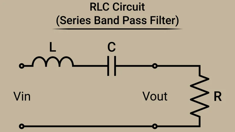
Passive bandpass filters rely on combinations of resistors, capacitors, and inductors to create resonance. A simple LC resonant circuit can produce a bandpass response where the center frequency depends on inductance and capacitance. However, practical passive designs suffer from insertion loss, limited control over gain, and dependency on source and load impedance. In contrast, an active bandpass filter uses an op amp together with RC networks to achieve the same filtering behavior without inductors. This significantly improves design flexibility and allows controlled voltage gain within the passband.
From a systems perspective, active designs also improve impedance behavior. The input impedance is typically high, meaning the filter does not load the preceding stage, while the output impedance remains low, allowing easier cascading of multiple stages in complex analog systems. A further advantage is stability in integrated signal chains. Passive designs often experience unwanted attenuation when connected to other stages, while active filters maintain consistent behavior regardless of load variations.
The main limitation of active designs is that their performance is constrained by the bandwidth of the op-amp. At higher frequencies, the filter’s roll-off and phase behavior begin to deviate from ideal theoretical predictions.
Recommended reading: Active Low Pass Filter Design and Implementation Wide-Band Bandpass: Cascaded High-Pass and Low-Pass Filters
When the required bandwidth is large compared to the center frequency, specifically when the ratio of upper cutoff to lower cutoff exceeds approximately ten, a dedicated second-order bandpass structure is often unnecessary. Instead, a practical approach is to cascade a high-pass filter and a low-pass filter, each designed independently. The high-pass stage defines the lower cutoff frequency, while the low-pass stage defines the upper cutoff. Together, they form an overall bandpass response.
In this architecture, the overall frequency response is the product of the individual transfer functions. This cascading method makes filter design modular and easier to scale, especially in complex analog systems such as instrumentation front ends. The center frequency of the resulting bandpass system is approximately the geometric mean of the two cutoff frequencies, while the bandwidth is determined by their difference. As bandwidth increases, the effective selectivity decreases, resulting in a more gradual roll-off.
Each stage may be implemented using standard active filter structures such as Sallen-Key or multiple feedback designs. These stages typically rely on carefully chosen resistor and capacitor values to control cutoff behavior while preserving stable gain. To avoid interaction between stages, each filter section should present high input impedance and low output impedance, which is naturally achieved using op amp buffering between stages. This ensures predictable behavior even when multiple stages are cascaded.
Recommended reading: What Is a Low-Pass Filter? Theory, Design & Practical Implementation
Narrow-Band Bandpass Topologies
For applications requiring a narrow bandwidth and high selectivity, cascaded high-pass and low-pass filters become inefficient. In such cases, dedicated second-order bandpass structures are used. These circuits generate a resonant response centered at a defined center frequency while simultaneously attenuating frequencies outside the passband. The sharpness of this response is governed by the quality factor, which defines how selective the filter is.
Common implementations include multiple-feedback topologies and Sallen-Key bandpass designs. Among these, the multiple-feedback configuration is more widely used due to its improved control over center frequency and bandwidth. In narrow-band applications, the goal is often to isolate a specific signal component within a noisy spectrum, making precise control of both gain and frequency response essential.
Multiple-Feedback (MFB) Bandpass Filter
The multiple-feedback bandpass filter is one of the most widely used active bandpass configurations. It uses a single op amp, two capacitors, and three resistors to create a second-order response with a well-defined center frequency. This topology operates in an inverting configuration, where the input signal is processed through a frequency-selective feedback network. The result is a bandpass response characterized by a peak at the center frequency and attenuation at both low and high frequencies.
The behavior of the circuit is defined by a second-order transfer function where the center frequency depends on resistor-capacitor relationships, while bandwidth is primarily controlled by feedback components. One of the advantages of this topology is that it allows relatively independent control of center frequency and bandwidth, making it suitable for precision filter design. It also provides stable performance in moderate-Q applications where selectivity is important, but extreme sharpness is not required.
However, as frequency increases, the performance becomes limited by the finite bandwidth of the op amp, and errors in component matching begin to affect accuracy. This is especially important in high-frequency analog systems where small deviations can distort the overall frequency response.
Sallen–Key Bandpass Filter
The Sallen-Key bandpass filter is a non-inverting configuration that extends the familiar Sallen-Key architecture used in low-pass and high-pass filter design. It uses a combination of resistors and capacitors in a frequency-selective network, while the op amp provides gain and buffering. The resulting response is smoother and easier to implement but offers less independent control over bandwidth and selectivity compared to multiple-feedback designs.
This topology is typically used in moderate-bandwidth applications where simplicity and non-inverting behavior are more important than precise Q control. Because the gain, center frequency, and quality factor are interconnected, tuning the circuit requires careful adjustment of component ratios. This makes it less suitable for high-selectivity or high-Q applications.
Twin-T Notch Bandpass Configuration
An alternative approach to bandpass filtering uses a twin-T network combined with an amplifier. The twin-T network inherently produces a deep notch at a specific frequency, and when placed inside an active feedback loop, the response becomes bandpass. Although this approach can achieve strong attenuation outside the passband, it depends heavily on precise matching of resistor and capacitor values. Small variations in component tolerances can significantly degrade performance. As a result, this topology is less commonly used in modern precision filter design but remains useful in educational demonstrations and simple analog filtering applications.
Recommended reading: Low Pass Filter vs High Pass Filter – Theory, Design, and Applications
State-Variable and Biquad Topologies
State-variable and biquad filters are advanced active filter topologies widely used in precision analog signal processing. Unlike simple first-order or second-order filters, these designs allow independent control of cutoff frequency, gain, and quality factor (Q), making them highly flexible for audio electronics, instrumentation, and communication systems. A state-variable filter typically uses multiple operational amplifiers to simultaneously generate low-pass, high-pass, and band-pass outputs from the same circuit. Because the frequency and Q can be adjusted independently, state-variable filters are ideal for tunable filters, parametric equalizers, and waveform analysis systems.
Biquad filters are second-order filter sections that implement specific transfer functions using active components and RC networks. They are commonly used in higher-order filter design because multiple biquad stages can be cascaded to achieve sharp roll-off and precise frequency response characteristics. Popular implementations include Tow-Thomas and KHN topologies, which provide excellent stability, low sensitivity to component tolerances, and accurate filter performance in demanding analog applications.
Kerwin–Huelsman–Newcomb (KHN) State-Variable Filter
The Kerwin–Huelsman–Newcomb (KHN) filter, commonly referred to as a state-variable filter, is a high-performance active filter architecture built using three op-amps arranged as two integrators and one summing amplifier. This structure is widely used in precision analog systems because it can simultaneously generate low-pass filter, high-pass filter, and bandpass filter outputs from the same circuit. In a state-variable configuration, the signal is processed through successive integration stages, which define the filter’s frequency response. The output nodes provide different filtered versions of the same input signal, allowing multi-output filtering without additional cascading stages.
One of the most important advantages of this topology is its ability to independently control the center frequency, quality factor, and gain. This makes it highly suitable for tunable analog systems where filter characteristics must be adjusted without redesigning the entire circuit. The damping factor (the inverse of Q) is primarily set through feedback resistors, while the integrator time constants are defined using matched resistor and capacitor combinations. This separation of control variables makes the state-variable filter extremely flexible in advanced filter design applications.
Because of its multi-stage structure, the KHN topology requires careful attention to op amp performance. At the center frequency, sufficient loop gain is required to maintain stability and accurate resonance. In practice, a minimum of 20 dB loop gain at the center frequency is recommended to ensure predictable behavior in high-Q operation. This architecture is widely used in analog synthesizers, adaptive audio systems, and precision instrumentation where dynamic adjustment of bandwidth and resonance is required.
Recommended reading: Active High Pass Filter: Theory, Design, and Applications Multiple Feedback (MFB) Low-Pass Filter
Tow–Thomas (Biquad) Filter
The Tow–Thomas filter is a classical biquad filter implementation derived from the state-variable architecture. It is one of the most widely used second-order active filter structures in analog electronics. This design uses multiple operational amplifiers to generate a quadratic transfer function in both the numerator and denominator, enabling precise control of resonant behavior. Typically, the circuit produces bandpass and low-pass outputs, and with additional summing stages, it can also realize high-pass and notch responses. The term “biquad” refers to the second-order nature of its transfer function, which provides strong control over both selectivity and stability. Each parameter in the circuit corresponds to a physical adjustment: one resistor sets the resonant frequency, another controls Q, and another defines gain.
Like the KHN topology, the Tow–Thomas filter is highly tunable. However, it requires multiple active devices, increasing component count and design complexity. Because of this, it is less common in cost-sensitive designs but widely used in precision analog systems. This topology is especially effective in applications requiring high-Q performance, such as instrumentation filters, adaptive equalizers, and signal analysis systems, where frequency precision is more important than simplicity. As with all high-Q analog filter structures, sufficient op amp loop gain at the cutoff frequency is critical. Without it, the filter response can degrade, causing shifts in center frequency and reduced selectivity.
Center Frequency, Bandwidth, and Quality Factor
All second-order bandpass filter designs are defined by three fundamental parameters: center frequency, bandwidth, and quality factor.
The center frequency is defined as the geometric mean of the lower and upper cutoff frequencies:
f₀ = √(fL · fH)
The bandwidth describes the width of the passband:
BW = fH − fL
The quality factor defines selectivity:
Q = f₀ / BW
These relationships are universal and apply to both active and passive bandpass systems. A higher Q value indicates a narrower bandwidth and sharper resonance, while a lower Q produces a wider passband with smoother response. From a system behavior perspective, Q strongly influences the time-domain response. High-Q filters tend to exhibit overshoot and ringing in response to step inputs, while low-Q designs produce smoother, more stable waveforms with minimal distortion.
In practical analog systems, Q is constrained by both component tolerances and op amp limitations. Multiple-feedback architectures typically achieve moderate Q values, while state-variable and biquad structures allow significantly higher Q operation, making them suitable for precision tuning applications.
Filter Response Approximations
The overall shape of an active bandpass filter is determined by the placement of poles in the complex frequency domain. Different mathematical approximations are used to control this pole placement, resulting in different trade-offs between flatness, selectivity, and phase behavior.
The most common response types include Butterworth, Chebyshev, Bessel, and elliptic responses. A Butterworth response provides a maximally flat passband and is widely used in general-purpose analog filtering. It offers balanced performance in both amplitude response and stability.
A Chebyshev response introduces controlled ripple in the passband to achieve a steeper transition and improved selectivity. This is useful when a sharper separation between frequency bands is required. A Bessel response prioritizes phase linearity and time-domain accuracy, preserving waveform shape even if roll-off is less aggressive. This makes it suitable for systems where signal integrity is more important than sharp frequency separation. Elliptic filters offer the steepest roll-off by introducing ripple in both the passband and stopband, making them suitable for highly selective applications.
In practical filter design, these responses are derived from low-pass prototypes and converted into bandpass equivalents using frequency transformation techniques. This process maps each low-pass pole into a pair of bandpass poles centered around the desired center frequency. Design tables from engineering references are commonly used to scale these prototypes into usable circuit values for implementation using Sallen-Key, multiple feedback, or state-variable topologies.
Op-Amp Selection and Non-Ideal Effects
The performance of an active bandpass system is strongly dependent on the characteristics of the op amp used in the design. Since the op-amp provides gain and active control of the filter response, its limitations directly affect accuracy and stability.
Gain-Bandwidth Product (GBW)
The gain-bandwidth product determines how well the operational amplifier can maintain gain at higher frequencies. For stable bandpass operation, the GBW must be significantly higher than the filter’s center frequency. A general design guideline is that GBW should be at least 100 times the relevant cutoff frequency. For higher gain or high-Q designs, the requirement increases proportionally. If the GBW is insufficient, the frequency response shifts, Q reduces, and the center frequency becomes inaccurate due to phase lag and reduced loop gain.
Slew Rate
The slew rate defines how quickly the output of the op amp can respond to rapid changes in the input signal. If the required rate exceeds the op-amp capability, waveform distortion occurs, especially near resonance, where signal amplitude is amplified. For sinusoidal signals, the minimum slew rate requirement is proportional to both frequency and peak-to-peak voltage. High-Q filters are particularly sensitive because resonance increases signal amplitude within the passband.
Open-Loop Gain and Stability
Finite open-loop gain affects the precision of pole placement in second-order filter designs. If insufficient, the filter’s center frequency shifts and Q decreases, reducing selectivity. At higher frequencies, open-loop gain naturally decreases, which limits achievable filter performance. This is a critical constraint in high-frequency analog systems.
Noise and Bias Effects
In narrow-band systems, noise performance becomes more important because the filter passes a limited range of frequencies. Although total integrated noise is reduced, the op-amp’s voltage noise can dominate the output signal. Bias currents also affect performance, especially in multiple-feedback topologies that use large resistor values. Using low-noise, low-bias op-amps improves stability and accuracy in precision applications.
Worked Design Example
A narrow-band active bandpass filter is designed with a center frequency of 1 kHz, quality factor Q=5Q = 5Q=5, and a mid-band gain of 10 using an inverting multiple-feedback (MFB) configuration. The MFB topology is selected because it allows independent control of center frequency and bandwidth using a single operational amplifier while maintaining a well-defined second-order response.
To simplify the design and scaling process, equal capacitor values are selected:
C1 = C2 = C = 10 nF
Using standard MFB bandpass filter design equations, the resistor values are calculated from the specified center frequency, quality factor, and gain.
The feedback resistor is calculated as:
R3 = Q / (πf0C)
R3 = 5 / (π × 1000 × 10 × 10^-9)
R3 ≈ 159 kΩ
The input resistor is calculated as:
R1 = Q / (G × 2πf0C)
R1 = 5 / (10 × 2π × 1000 × 10 × 10^-9)
R1 ≈ 7.96 kΩ
The second resistor is calculated as:
R2 = Q / [(2Q^2 − G) × 2πf0C]
R2 = 5 / [(2 × 5^2 − 10) × 2π × 1000 × 10 × 10^-9]
R2 ≈ 1.99 kΩ
The calculated resistor values are then rounded to the nearest standard E24 series values:
R1 = 8.2 kΩ
R2 = 2.0 kΩ
R3 = 160 kΩ
At this stage, a slight deviation in center frequency is expected due to resistor rounding. This deviation is typically corrected by adjusting the capacitor values instead of the resistors, since capacitor scaling preserves the designed gain and quality factor relationships more reliably.
A consistency check is then performed using the standard MFB bandpass relationships:
f0 = (1 / 2πC) × √[(R1 + R3) / (R1R2R3)]
Q = πf0R3C
These expressions confirm that R3 primarily sets the resonant frequency, while R2 dominates bandwidth control and therefore Q. R1 primarily influences gain scaling.
Component | Value | Function |
C1, C2 | 10 nF | Sets frequency scaling |
R1 | 8.2 kΩ | Gain scaling via mid-band amplification |
R2 | 2.0 kΩ | Controls bandwidth and Q |
R3 | 160 kΩ | Sets the center frequency |
Op-Amp Selection and Practical Constraints
The operational amplifier must be carefully selected to preserve both the magnitude and phase characteristics of the designed transfer function.
For this design, the minimum gain-bandwidth product (GBW) requirement is:
GBW ≥ 100 × Q × f0
GBW ≥ 100 × 5 × 1000
GBW ≥ 500 kHz
In practice, an operational amplifier with a bandwidth of 1 MHz or greater is preferred to provide sufficient phase margin and minimize Q degradation caused by finite open-loop gain.
The slew rate requirement is given by:
SR ≥ 2πf0VPP
where:
VPP = peak-to-peak output voltage
High-Q bandpass filters are especially sensitive because resonance amplifies signals near the center frequency, increasing the instantaneous rate of voltage change required from the op-amp.
For higher selectivity designs, such as:
Q = 20
Single-op-amp MFB topologies become less stable due to component tolerance sensitivity and limited loop gain. In these situations, state-variable or biquad filter topologies are generally preferred because they independently control frequency, Q, and gain.
In state-variable filters, the center frequency is determined by the integrator time constants:
f0 = 1 / (2πRC)
while the quality factor is adjusted separately through feedback ratios, allowing stable tuning without affecting the resonance frequency.
To maintain filter accuracy and prevent pole migration, it is generally recommended to preserve at least:
20 dB of loop gain at f0
Recommended reading: Operational Amplifier: Theory, Design and Applications for Engineers
Applications
Active bandpass filters are widely used in systems requiring frequency isolation combined with signal conditioning. In audio systems, they are used in equalizers and vocoders where specific spectral bands must be selectively amplified or attenuated. Multiple bandpass stages are often cascaded to form graphic equalizers with approximately octave spacing and moderate Q values near unity. In communication systems, bandpass filters define channel selectivity in intermediate-frequency (IF) stages. While high-frequency IF designs often rely on passive LC or crystal filters, active bandpass filters remain common at baseband and low-IF stages where op-amp limitations are acceptable.
In biomedical systems such as ECG and pulse oximetry, bandpass filtering is essential to remove baseline wander and high-frequency noise while preserving physiological signal components typically in the 0.5–40 Hz range. In these applications, low noise density and high input impedance are critical requirements. In mechanical and vibration analysis, bandpass filters isolate resonant modes of structures. Q values between 2 and 10 are commonly used to balance selectivity with temporal stability of the measured waveform.
In tone decoding systems such as DTMF detection, multiple bandpass filters tuned to specific frequencies are used to identify signal pairs. Accuracy depends strongly on Q stability and center frequency precision.
Conclusion
Active bandpass filters provide a compact and highly flexible method of frequency-selective signal processing without the use of inductors. Wide-band systems are efficiently implemented using cascaded high-pass and low-pass stages, while narrow-band applications rely on MFB or Sallen–Key second-order topologies. For high-Q or precision filtering requirements, state-variable and biquad architectures provide superior performance due to their independent control of center frequency, bandwidth, and gain.
Ultimately, filter performance is governed not only by component selection but also by op-amp limitations, including gain-bandwidth product, slew rate, open-loop gain, and noise characteristics. Proper matching of these constraints is essential to preserve theoretical filter behavior in practical implementations.
Frequently Asked Questions (FAQ) – Active Bandpass Filter Design
1. What is an active bandpass filter?
An active bandpass filter is an electronic circuit that uses an operational amplifier (op-amp) with resistors and capacitors to allow a specific range of frequencies to pass while attenuating frequencies below and above that range.
2. How is an active bandpass filter different from a passive bandpass filter?
A passive bandpass filter uses only resistors, capacitors, and inductors and cannot provide gain. An active bandpass filter uses an op-amp, which allows signal amplification, better impedance matching, and improved control of the frequency response.
3. What determines the center frequency of a bandpass filter?
The center frequency is mainly determined by the values of the resistors and capacitors in the circuit. In many second-order designs, it is related to the geometric mean of the lower and upper cutoff frequencies.
4. What is the role of the quality factor (Q) in bandpass filters?
The quality factor (Q) defines the selectivity of the filter. A higher Q results in a narrower bandwidth and sharper peak at the center frequency, while a lower Q produces a wider passband with smoother response.
5. Why are op-amps used in active bandpass filters?
Op-amps are used to provide gain, isolate stages (high input impedance and low output impedance), and improve overall stability and performance of the filter without needing inductors.
6. What are common active bandpass filter topologies?
The most common topologies include Multiple Feedback (MFB), Sallen-Key, and state-variable (biquad) filters. Each offers different trade-offs in terms of complexity, stability, and control over frequency parameters.
7. Where are active bandpass filters commonly used?
They are widely used in audio processing, biomedical signal systems (such as ECG filtering), communication systems, and instrumentation, where isolating a specific frequency range is important.
References
[1] G. S. Moschytz and T. W. Moskowitz, Analog Circuit Theory and Filter Design. New York, NY, USA: Wiley, 2009.
[2] R. Schaumann, M. E. Van Valkenburg, and E. Sánchez-Sinencio, Design of Analog Filters, 2nd ed. Oxford, U.K.: Oxford University Press, 2013.
[3] Texas Instruments, “Filter Design in Thirty Seconds,” Application Report SLOA093. [Online]. Available: https://www.ti.com/lit/an/sloa093/sloa093.pdf
[4] Massachusetts Institute of Technology (MIT), “Operational Amplifiers (6.101 Reference Notes).” [Online]. Available: https://web.mit.edu/6.101/www/reference/op_amps_everyone.pdf
[5] Wevolver, “Active Low-Pass Filter Design and Implementation: Theory and Applications,” 2024. [Online]. Available: https://www.wevolver.com/article/low-pass-filter-vs-high-pass-filter-theory-design-and-applications
[6] Wevolver, “Operational Amplifier: Theory, Design, and Applications for Engineers,” 2024. [Online]. Available: https://www.wevolver.com/article/operational-amplifier-theory-design-and-applications-for-engineers
in this article
1. Key Takeaways2. Introduction3. Active vs Passive Bandpass Filters4. Narrow-Band Bandpass Topologies5. Multiple-Feedback (MFB) Bandpass Filter6. Sallen–Key Bandpass Filter7. Twin-T Notch Bandpass Configuration8. State-Variable and Biquad Topologies 9. Center Frequency, Bandwidth, and Quality Factor10. Filter Response Approximations11. Op-Amp Selection and Non-Ideal Effects12. Worked Design Example13. Op-Amp Selection and Practical Constraints14. Applications15. Conclusion16. Frequently Asked Questions (FAQ) – Active Bandpass Filter Design17. References