Verilog HDL: Fundamentals for FPGA and ASIC Design
A definitive guide to Verilog HDL — syntax, modeling styles, and its role in the FPGA/ASIC design flow, explained for engineers.

08 Jul, 2026. 15 minutes read

Key Takeaways
Verilog is an IEEE-standard hardware description language. It uses a textual syntax to model digital logic and supports four-state values (0, 1, X, Z) that correspond to high, low, unknown, and high-impedance levels [1].
Modules form the building blocks of Verilog designs. A module encapsulates ports, nets, registers, and procedural logic. Modules can be instantiated hierarchically to build complex systems.
Nets and variables differ fundamentally. Nets (e.g., wire) model physical connections and cannot store values, while variables (e.g., reg) hold a value between assignments[1]. (Note: SystemVerilog later introduced logic as a unified variable type, but standard Verilog uses reg.)
Blocking (=) and non-blocking (<=) assignments have different scheduling semantics. Blocking assignments execute sequentially; non-blocking assignments evaluate right-hand sides then update left-hand sides together, which avoids race conditions and should be used for synchronous logic[3].
Verilog simulation supports constructs that may not synthesize. initial blocks, delay operators (#), fork/join and file I/O are powerful for testbenches but are usually excluded from the synthesizable subset[11].
A complete digital design flow includes modeling, simulation, synthesis, place-and-route and implementation. Tools such as Icarus Verilog, ModelSim/QuestaSim or Verilator provide simulation, while synthesis and implementation are handled by FPGA tools like Vivado and Quartus, or ASIC tools such as Synopsys Design Compiler[7].
Introduction
Digital circuits and complex electronic systems power everything from microprocessors to communication infrastructure. As systems become more complex, hand-drawing schematics at the gate level becomes impractical. Hardware description languages (HDLs) allow engineers to describe circuits at higher levels of abstraction. Verilog, along with its extension SystemVerilog, is among the most popular HDLs used in industry today. Unlike software languages that execute sequentially, Verilog describes concurrent hardware behavior. Understanding Verilog is essential for anyone working in register-transfer level (RTL) design, FPGA and ASIC development or hardware verification.
This article introduces Verilog HDL from an engineering perspective. We begin with a brief history and standardization timeline, then explore abstraction levels, language fundamentals, modeling constructs and assignments. We discuss simulation versus synthesis, the importance of testbenches, and how Verilog fits into the FPGA/ASIC design flow. We also compare Verilog with VHDL and SystemVerilog to help you choose the right language for your project.
Why Do We Need a Hardware Description Language?
Modern digital systems contain billions of transistors, and hand-crafting gate-level schematics at that scale is not just impractical — it's effectively impossible to verify or maintain. As chip complexity grew through the 1970s and 80s, engineers needed a way to describe circuit behavior and structure using text-based code rather than drawings, much like software abstracts away raw machine instructions.
Hardware description languages solve this by letting engineers work at higher levels of abstraction — describing what a circuit should do (behavioral level) or how it's structured (structural/RTL level) — while tools handle the translation down to actual gates and transistors. Critically, an HDL must capture two things that standard programming languages were not designed for:
Concurrency — real hardware doesn't execute one operation at a time; every gate, register, and wire can change state simultaneously.
Timing — circuit behavior depends on delays, clock edges and signal propagation, none of which exist in a conventional software execution model.
This is the fundamental reason HDLs like Verilog exist as a distinct category of language, separate from general-purpose programming languages: they model hardware as it actually behaves, not as a sequence of instructions.
What is Verilog?
Verilog is a hardware description language (HDL) used to design, model, and simulate digital circuits — chips, CPUs, FPGAs— before they're physically built. Engineers write code describing how hardware behaves instead of drawing schematics by hand, and that code can be simulated and later converted into real silicon.
It uses a four-state value system for every signal:
- 0 — logic zero
- 1 — logic one
- x — unknown
- z — high impedance (not driven)
This matters because x and z help catch real bugs during simulation — uninitialized registers, bus contention, tri-state driver conflicts — before a chip gets fabricated.
Verilog also supports concurrency (many parts of a circuit run simultaneously, unlike normal step-by-step code) and event-driven simulation (the simulator only recalculates when something actually changes, like a clock edge), which together let engineers verify complex designs before committing to silicon.
It became an IEEE standard in 1995 (IEEE standard 1364), was revised in 2001 and 2005, and eventually merged with SystemVerilog into IEEE 1800-2009.
The Register-Transfer Level (RTL)
Although Verilog can describe systems at various levels of abstraction, most FPGA/ASIC designs are written at the register-transfer level. RTL describes how data moves between registers under the control of a clock and how combinational logic transforms data between registers. By abstracting away transistor-level details, RTL captures the essential behavior needed for synthesis, while still giving designers control over trade-offs such as pipelining, resource sharing, and clock frequency.
History and Standardization
Understanding Verilog's evolution helps make sense of its design decisions and limitations. Key milestones include:
Year | Event | Notes |
1984-1985 | Gateway Design Automation releases Verilog | Original proprietary language for simulation and synthesis. |
1990 | Cadence Design Systems makes Verilog public | Formation of the Open Verilog International (OVI) group[1]. |
1995 | IEEE 1364-1995 | First standardization of Verilog HDL. |
2001 & 2005 | IEEE 1364-2001, 1364-2005 | Added features such as generate statements, signed arithmetic and improvements to synthesis[1]. |
2005 | SystemVerilog (IEEE 1800-2005) | Combined Verilog with verification enhancements, object-oriented features and constrained randomization. |
2009 | SystemVerilog merges with Verilog | Final unification under IEEE 1800-2009, superseding IEEE 1364. |
These revisions modernized Verilog while maintaining backward compatibility. Today most commercial tools support Verilog-2005 and SystemVerilog. When writing new designs, adopt at least the 2005 standard to benefit from generate loops, case improvements and signed types.
Abstraction Levels and Modeling Styles
Verilog supports multiple levels of abstraction, enabling designers to choose the appropriate level for each part of a system:
Behavioral modeling describes a system algorithmically. For example, a high-level description of a digital filter can use if statements and arithmetic operations. Behavioral models are easy to write but may not be directly synthesizable.
RTL modeling expresses how data flows between registers under clock control, typically combining dataflow constructs (continuous assign statements for combinational logic) with synthesizable always blocks for clocked (sequential) logic. This is the dominant, synthesizable style used in real FPGA/ASIC design.
Gate-level modeling instantiates primitive gates (and, or, xor, bufif) and structural connections. This level is used for post-synthesis netlists.
Switch-level modeling allows transistor-level descriptions using nmos, pmos and primitives. It is rarely used in modern RTL design because detailed transistor behavior is captured in standard cell libraries.
Further Reading: PMOS vs NMOS: Unraveling the Differences in Transistor Technology
Selecting the right abstraction balances simulation speed, ease of coding and synthesizability. For most FPGA/ASIC design, combine behavioral statements inside synthesizable always blocks while avoiding constructs unsupported by synthesis.
Language Fundamentals
Modules and Ports
Modules are the fundamental building blocks of Verilog designs. A module encapsulates ports, internal signals, parameters, and behavioral or structural code. Ports may be inputs, outputs, or bidirectional (inout). Each port has a direction and optionally a width (a vector). Consider a two-input AND gate:
module and2 (
    input  wire a,
    input  wire b,
    output wire y
);
    assign y = a & b;  // continuous assignment
endmodule
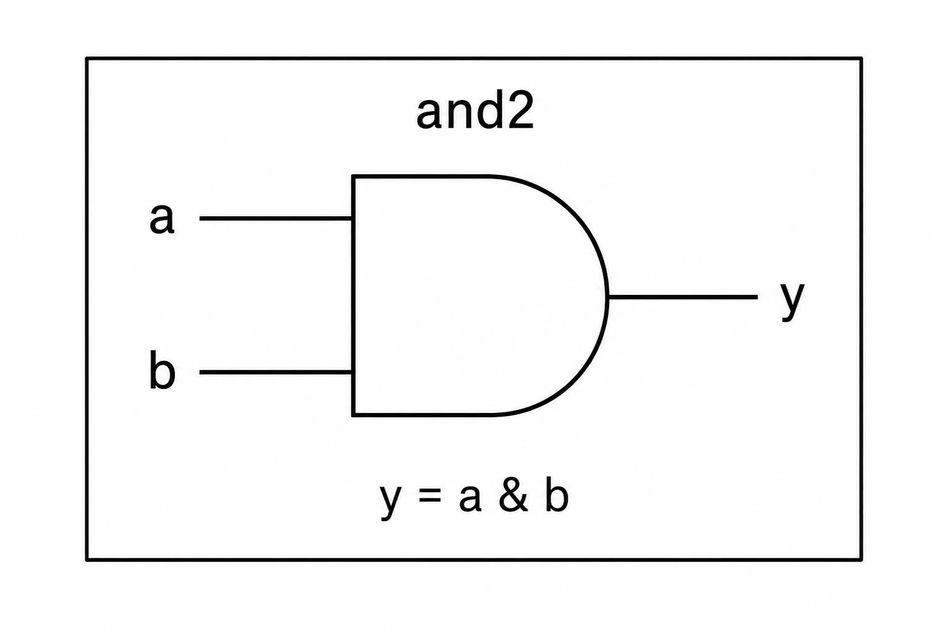
Verilog and2 module: a two-input AND gate with ports a, b, and y, implemented using a continuous assignment (assign y = a & b).
Module ports use wire by default, meaning they do not store values and reflect whatever is driven on them[10]. To create a multi-bit bus, declare a vector width, e.g., input [3:0] data. Modules can be instantiated hierarchically, forming a tree of interconnected components.
Nets (Wire) Versus Variables (Reg/Logic)
Verilog distinguishes between nets and variables. Nets (wire, tri, etc.) represent physical wires that connect drivers. Nets do not store values; instead they show the resolved logic value based on the drivers. Variables (reg in Verilog, logic in SystemVerilog) represent storage elements that hold their value until assigned. The IEEE standard notes that nets are generally used to model structural connections while variables hold values between assignments[1]. Nets default to high impedance (z) if unconnected; variables initialize to x (unknown) during simulation[1] — though this x-initialization is a simulation-time guarantee, not necessarily reproduced by synthesized hardware, where actual power-on register state depends on the target device.
Using the correct type is essential for synthesis. For example, consider this register and combinational assignment:
module reg_and_comb (
    input  wire clk,
    input  wire rst_n,
    input  wire d,
    output reg  q
);
    // sequential logic: use non-blocking assignment
    always @(posedge clk or negedge rst_n) begin
        if (!rst_n)
            q <= 1'b0;
        else
            q <= d;
    end
endmodule
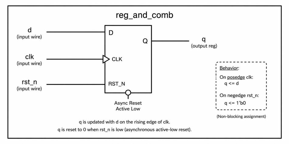
D flip-flop with asynchronous active-low reset: the reg_and_comb Verilog module updates q with d on the rising edge of clk, and resets q to 0 when rst_n goes low, using non-blocking assignment (<=).
Here, q is a variable (reg) because it stores its value across clock cycles. Using a wire for q would be illegal because wires cannot be assigned within an always block. SystemVerilog introduces the logic type, which resolves confusion by replacing reg and wire for most single-driver signals [2].
Parameters, Vectors, and Buses
Parameters allow you to parameterize module behavior at compile time. For instance, a parameterized multiplexer can have a generic data width:
module mux #(parameter WIDTH=8) (
    input  wire [WIDTH-1:0] a,
    input  wire [WIDTH-1:0] b,
    input  wire sel,
    output wire [WIDTH-1:0] y
);
    assign y = sel ? b : a;
endmodule
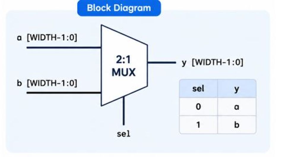
Parameterized 2-to-1 multiplexer
Vector ports and signals are declared with [msb:lsb] ranges. Always specify bit widths explicitly for ports and internal signals to avoid synthesis ambiguities. Parameters can be overridden at instantiation or using defparam (deprecated). Avoid defparam in new code; use named parameter overrides instead.
Continuous Assignments
Continuous assignments use the assign keyword to drive a net with an expression. These assignments are concurrent; they continuously evaluate as their right-hand side changes. For simple combinational logic such as multiplexers or adders, continuous assignments provide concise descriptions:
assign y = (sel == 1'b0) ? a : b;
Because continuous assignments drive nets, the left-hand side must be a net type (wire or tri). For synthesizable designs, avoid using continuous assignments with delay operators (e.g., assign #5 y = a & b) because delays are ignored by synthesis.
Procedural Blocks: initial and always
Verilog uses procedural blocks to describe behavior that cannot be expressed with simple continuous assignments. There are two kinds:
initial blocks execute once at simulation time 0. They are intended for testbenches or for initializing memories. They are generally not synthesizable for ASIC targets, since silicon has no built-in "time 0" initialization mechanism[11]. However, many FPGA synthesis tools (e.g., Vivado, Quartus) do support simple initial block assignments to set register power-up states or preload block RAM contents via the bitstream. [11]. For example, to preload a memory in a simulation you might write:
initial begin
    mem[0] = 8'hDE;
    mem[1] = 8'hAD;
    mem[2] = 8'hBE;
    mem[3] = 8'hEF;
end
always blocks execute repeatedly. They can model combinational or sequential logic depending on their sensitivity list. For combinational logic, write always @* or always @(*), which automatically includes every signal read inside the block — not just right-hand-side signals, but also condition expressions in if/case statements. For sequential logic, specify clock edges: always @(posedge clk) or always @(posedge clk or negedge rst)[11]. This block is synthesizable and generates flip-flops or latches depending on the code.
Inside always blocks you uses procedural assignments. There are two types: blocking assignments (=) and non-blocking assignments (<=). Understanding their differences is critical.
Blocking vs Non-blocking Assignments
Blocking assignments execute sequentially within a procedural block: the left-hand side updates immediately, and subsequent statements see the new value. Non-blocking assignments evaluate the right-hand side at the beginning of the time slot and update the left-hand side at the end. This separation allows concurrent updates and prevents race conditions.Industry best practice — reflected in the IEEE standard's assignment semantics and reinforced by widely cited guidelines recommends using blocking assignments for combinational logic and non-blocking assignments for synchronous logic [3]. [3]. Cummings' classic paper on non-blocking assignments explains that blocking assignments are a one-step process (evaluate and update), whereas non-blocking assignments are a two-step process (evaluate early, update late)[3]. Sigasi and other tutorials reinforce this rule of thumb[8].
Consider a simple D flip-flop with asynchronous reset:
module dff (
    input  wire clk,
    input  wire rst_n,
    input  wire d,
    output reg  q
);
    always @(posedge clk or negedge rst_n) begin
        if (!rst_n) begin
            q <= 1'b0;        // non-blocking assignment
        end else begin
            q <= d;           // sample d on rising clock
        end
    end
endmodule
If we mistakenly used blocking assignments (q = d;) in sequential logic, the updated value of q could feed back into combinational logic within the same time slot, creating race conditions. Non-blocking assignments schedule all updates to occur simultaneously at the end of the time slot, ensuring predictable behavior.
Example: 2:1 Multiplexer (Combinational)
Below is a synthesizable 2:1 multiplexer described using both continuous assignment and an always block:
module mux2 (
    input  wire a,
    input  wire b,
    input  wire sel,
    output wire y
);
    // Dataflow style with assign
    assign y = sel ? b : a;
endmodule


module mux2_always (
    input  wire a,
    input  wire b,
    input  wire sel,
    output reg  y
);
    // Combinational always block
    always @(*) begin
        if (sel == 1'b0)
            y = a;    // blocking assignment for combinational logic
        else
            y = b;
    end
endmodule
Both versions synthesize to the same logic. The assign form is concise; the always form allows more complex conditions or case statements.
Example: Counter with Non-blocking Assignments
Sequential logic should use non-blocking assignments. A simple up-counter illustrates this pattern:
module counter #(parameter WIDTH=8) (
    input  wire clk,
    input  wire rst_n,
    output reg  [WIDTH-1:0] count
);
    always @(posedge clk or negedge rst_n) begin
        if (!rst_n)
            count <= {WIDTH{1'b0}};
        else
            count <= count + 1'b1;
    end
endmodule
Here count is a variable that retains its state. Non-blocking assignment (<=) ensures that count + 1 uses the previous count value, not the value being updated.
Further Reading: FPGA vs ASIC: Key Differences, Costs, and How to Choose
Simulation vs Synthesis
Simulation uses an event-driven algorithm to evaluate HDL descriptions over time. Every signal change schedules events, and the simulator processes them in order. Synthesis, by contrast, translates a subset of Verilog into a gate-level netlist that implements the same behavior in hardware. This distinction leads to constructs that are legal in simulation but not synthesizable:
initial blocks execute once at time 0 and are generally not synthesizable for ASIC targets, though many FPGA synthesis tools support simple initial block assignments for register power-up states[11].
Delays (#10) are simulation-only; they are ignored by synthesis. Avoid using delays in RTL code.
fork/join create parallel processes in simulation but are not synthesizable in most synthesis tools.
File I/O tasks such as $fopen and $fscanf are powerful for testbenches but not synthesizable. $readmemh and $readmemb are an exception, however, since they are commonly supported by FPGA synthesis tools for preloading memory (RAM/ROM) contents
$display/$monitor print to the console during simulation. They are used for debugging and testbenches[4].
Synthesis tools support a synthesizable subset of Verilog. Use only constructs that map directly onto hardware structures: always @(posedge clk), combinational always @(*), continuous assignments, simple control structures (if, case), arithmetic operators and bitwise operations. Avoid unintentionally inferred latches, which occur when an output isn't assigned in every possible branch of an if/case statement (e.g., a missing else or default), by ensuring all outputs are assigned in all branches. Separately, always use @(*) or specify all relevant signals in the sensitivity list to prevent simulation/synthesis mismatches.
Testbenches and Verification
Before committing a design to synthesis, you must verify that it behaves correctly. A testbench is a Verilog module that instantiates the device under test (DUT), applies stimulus and checks responses. Testbenches run only in simulation and can leverage constructs not intended for synthesis.
Key elements of a testbench include:
Clock and reset generation. Use an initial block or always block with delays to generate clocks. For example:

 reg clk;
initial clk = 0;
always #5 clk = ~clk;  // 100 MHz clock (period = 10)
Stimulus application. Drive inputs to the DUT using procedural assignments or tasks. For sequential designs, wait for clock edges using @(posedge clk).
Monitoring outputs. Use $display to print messages at specific times and $monitor to continuously display variable changes[4].
Self-checking. Compare outputs against expected values and report pass/fail conditions. Simple if statements can be used, or you can write tasks for repeated checks.
Waveform dumping. Use $dumpfile and $dumpvars to generate waveforms for analysis in tools like GTKWave.
A minimal testbench skeleton might look like this:
module tb_counter;
    reg clk;
    reg rst_n;
    wire [3:0] count;


    // Instantiate DUT
    counter #(.WIDTH(4)) dut (
        .clk (clk),
        .rst_n (rst_n),
        .count (count)
    );


    // Clock generator
    initial clk = 0;
    always #5 clk = ~clk;


    // Stimulus
    initial begin
        rst_n = 0;
        #12;          // hold reset low for one+ cycles
        rst_n = 1;
        repeat (10) @(posedge clk);
        $finish;
    end


    // Monitor
    initial $monitor("%0t: count = %b", $time, count);
endmodule
This testbench toggles the clock every 5 time units, asserts reset for the first few cycles, and then allows the counter to increment. The $monitor statement prints the count value whenever it changes[4].
Advanced verification often uses frameworks like UVM (Universal Verification Methodology) built on SystemVerilog. Nevertheless, simple Verilog testbenches are invaluable for early functional verification and can be used with open-source simulators such as Icarus Verilog or Verilator. Icarus Verilog is a free, open-source Verilog simulator that has been under development since the late 1990s; it provides solid simulation capabilities for most designs and is often paired with tools like Yosys for open-source synthesis [9].
Recommended Reading: What is VHDL? A Complete Guide with Syntax, Examples & IEEE Standards
Digital Design Flow: From RTL to Silicon
Designing digital hardware requires more than writing Verilog. A typical FPGA/ASIC flow comprises multiple stages:
Coding: Write the RTL code, parameterize modules and perform design entry.
Simulation: Use a simulator (Icarus Verilog, ModelSim/QuestaSim, Verilator, Cadence Xcelium) to verify functionality. Simulation ensures that the design meets specifications and that there are no race conditions or latches.
Synthesis: Translate the RTL into a gate-level netlist using tools like Xilinx Vivado, Intel Quartus, Lattice Radiant or Synopsys Design Compiler. The synthesis tool maps the design into technology-specific primitives and optimizes for area, speed or power[7].
Place and Route (P&R): For FPGAs, the tool places logic elements (LUTs, flip-flops) onto the device and routes signals. For ASICs, place-and-route arranges standard cells and wires on silicon. Timing analysis ensures that clock periods meet requirements. Tools such as Vivado or Intel Quartus perform these steps automatically.
Bitstream or GDSII generation: For FPGAs, generate a bitstream file loaded onto the device. For ASICs, produce a GDSII layout for fabrication. Post-synthesis simulation and gate-level simulation verify the design after mapping.
Programming and Testing: Program the FPGA, run hardware verification, and iterate as needed. For ASICs, fabricate prototypes and perform silicon debug.
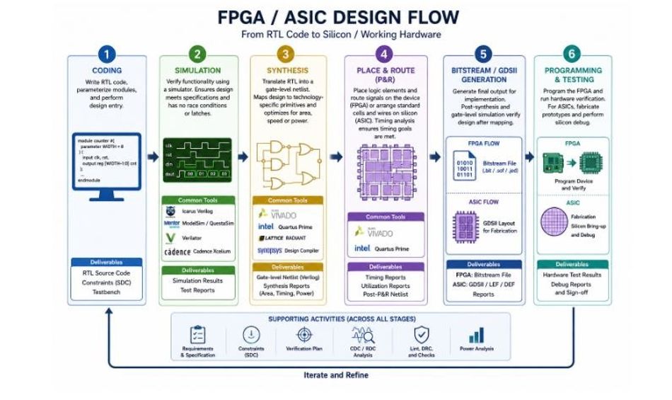
FPGA/ASIC design flow from RTL to silicon, showing the six major stages.
Open-source flows also exist. For example, a complete free toolchain might use Icarus Verilog or Verilator for simulation, Yosys for synthesis, NextPNR for place and route, and the open-source toolchain from Lattice for programming small FPGAs.
Further reading: The Ultimate Guide to ASIC Design: From Concept to Production
Verilog vs VHDL vs SystemVerilog
Choosing the right HDL depends on project requirements, team expertise, and tool support. The table below summarizes key differences and similarities among Verilog, VHDL, and SystemVerilog.
Feature | Verilog | VHDL | SystemVerilog |
Origins/Standard | Introduced in the mid-1980s, standardized as IEEE 1364 (1995/2001/2005)[5] | Developed under U.S. DoD, standardized as IEEE 1076; strong Ada influence[5] | Superset of Verilog (IEEE 1800-2005/2009); combines design and verification features[6] |
Syntax style | C-like, concise; weakly typed; faster to write[6] | Verbose, strongly typed; explicit type conversions and packages[6] | Extends Verilog syntax; adds logic type, classes, interfaces, and assertions |
Typing | Weak typing; implicit conversions allowed; variables declared with reg | Strong typing: signals must be declared with explicit types | Logic replaces reg and wire for single-driver signals; strong but flexible typing |
Use cases | Dominant in ASIC design and widely supported by synthesis and verification tools | Popular in defense/aerospace and safety-critical domains; encourages discipline and readability | Standard for verification (UVM), advanced RTL design, constrained random testing |
Tool support | Supported by all major FPGA/ASIC tools; open-source simulators available | Supported by all major tools, some IP cores are only available in VHDL | Requires tools that support SystemVerilog; many modern tools do |
Learning curve | Easier for those with a C background | Steeper due to verbosity and type system | Slightly steeper than Verilog because of additional features |
Both Verilog and VHDL can describe functionally identical hardware. The choice often hinges on team familiarity, existing IP libraries, and project requirements. SystemVerilog integrates advanced features such as classes, interfaces, assertions, randomization and covergroups, making it the preferred language for verification and modern ASIC design.
Recommended Reading: Verilog vs VHDL: A Comprehensive Comparison
Conclusion
Verilog has been central to digital design for over three decades. Its C-like syntax, hierarchical modules, four-state logic, and support for concurrent modeling make it ideal for describing and simulating hardware at the register-transfer level. By distinguishing nets and variables, using blocking vs non-blocking assignments appropriately, and leveraging testbenches, engineers can produce reliable, synthesizable RTL code.
HDL practice continues to evolve. SystemVerilog extends Verilog with advanced verification constructs, object-oriented programming and interfaces, while High-level synthesis (HLS) tools enable modeling in C++, SystemC, or Python that compiles into Verilog. Meanwhile, open-source tools such as Icarus Verilog, Verilator, and Yosys democratize hardware design. Regardless of the evolution, a solid grasp of Verilog remains indispensable.
FAQ
What is Verilog used for?
Verilog is a hardware description language used to model digital circuits. Engineers use it to specify how logic gates, registers, and interconnects behave; to simulate designs before fabrication; and to synthesize gate-level implementations for FPGAs or ASICs. Verilog's concurrent semantics and four-state logic enable accurate representation of hardware[1].
How do blocking and non-blocking assignments differ?
Blocking assignments (=) execute sequentially within an always block, updating the left-hand side immediately. Non-blocking assignments (<=) evaluate all right-hand sides first and update left-hand sides simultaneously at the end of the time slot, which prevents race conditions. Use blocking assignments for combinational logic and non-blocking assignments for sequential logic[3].
What are nets and variables in Verilog?
Nets (e.g., wire, tri) model physical connections and reflect the resolved value of all drivers; they do not store values. Variables (reg in Verilog, logic in SystemVerilog) represent storage elements and hold a value until assigned[1]. Choosing the correct type is essential for writing synthesizable code.
How do I write a testbench?
A testbench is a Verilog module that instantiates your design, generates clock and reset signals, applies stimulus, and checks outputs. Use initial blocks for one-time setup, use delays (#) or event controls (@(posedge clk)) to sequence stimulus, and use $display or $monitor to observe signals[4]. Testbenches are not synthesized; they run only in simulation.
Can Verilog describe both combinational and sequential logic?
Yes. Use continuous assign statements or always @(*) blocks with blocking assignments to model combinational logic. Use always @(posedge clk [or negedge reset]) blocks with non-blocking assignments to model synchronous sequential logic. Avoid unintended latches by assigning every output in every branch of an if/case statement; separately, use @(*) or complete sensitivity lists to prevent simulation/synthesis mismatches.
What tools support Verilog?
Simulation tools include Icarus Verilog, Verilator (a cycle-accurate simulator that translates Verilog to C++), ModelSim/QuestaSim and Xcelium. Synthesis tools include Xilinx Vivado, Intel Quartus Prime, Synopsys Design Compiler and Lattice Radiant[7]. For open-source flows, Yosys performs synthesis and NextPNR performs place-and-route for certain FPGA families.
How does Verilog compare to VHDL and SystemVerilog?
Verilog features concise, C-like syntax and is weakly typed; VHDL is verbose and strongly typed[6]. SystemVerilog extends Verilog with object-oriented constructs, interfaces and advanced verification features, making it the preferred language for modern verification environments[6]. All three languages are supported by major FPGA and ASIC toolchains[5].
References
[1] IEEE, "IEEE Standard for Verilog Hardware Description Language," IEEE Std 1364. [Online]. Available: https://standards.ieee.org/ieee/1364/3641/
[2] Siemens EDA, "What's the Deal with Those wires and reg's in Verilog," Verification Horizons, May 3, 2013. [Online]. Available: https://blogs.sw.siemens.com/verificationhorizons/2013/05/03/wire-vs-reg/
[3] C. E. Cummings, "Nonblocking Assignments in Verilog Synthesis, Coding Styles That Kill!," presented at Synopsys Users Group (SNUG), San Jose, CA, 2000, Rev. 1.2. [Online]. Available: https://csg.csail.mit.edu/6.375/6_375_2009_www/papers/cummings-nonblocking-snug99.pdf
[4] Cornell University, School of Electrical and Computer Engineering, "A Verilog HDL Test Bench Primer." [Online]. Available: https://people.ece.cornell.edu/land/courses/ece5760/Verilog/LatticeTestbenchPrimer.pdf
[5] BLT Inc., "Verilog vs VHDL: Choosing the Right HDL for FPGA Design," May 27, 2025. [Online]. Available: https://bltinc.com/2025/05/27/verilog-vhdl/
[6] Cadence, "Types of HDLs Explained," 2024. [Online]. Available: https://resources.pcb.cadence.com/blog/2024-types-of-hdls-explained
[7] Wikipedia, "Logic Synthesis." [Online]. Available: https://en.wikipedia.org/wiki/Logic_synthesis
[8] Sigasi, "Verilog Assignments: Blocking or Non-blocking?" [Online]. Available: https://www.sigasi.com/tech/verilog_assignments_blocking_nonblocking/
[9] S. Williams, "Icarus Verilog (iverilog) Project." [Online]. Available: https://github.com/steveicarus/iverilog
[10] Verilog Pro, "Verilog reg, Verilog wire, SystemVerilog logic: What's the Difference?" [Online]. Available: https://www.verilogpro.com/verilog-reg-verilog-wire-systemverilog-logic/
[11] Arm Developer, "Verilog and SystemVerilog Synthesizable Subset," Arm Developer Documentation, v. 09.02. [Online]. Available: https://developer.arm.com/documentation/100972/0902/verilog-95--verilog-2001--and-systemverilog-support/synthesizable-subset
in this article
1. Key Takeaways2. Introduction3. Why Do We Need a Hardware Description Language?4. What is Verilog?5. History and Standardization6. Abstraction Levels and Modeling Styles7. Language Fundamentals8. Procedural Blocks: initial and always9. Simulation vs Synthesis10. Testbenches and Verification11. Digital Design Flow: From RTL to Silicon12. Verilog vs VHDL vs SystemVerilog13. Conclusion 14. FAQ15. References