Subtractive Manufacturing: A Guide for Digital Design and Hardware Engineers
Subtractive manufacturing is the backbone of modern product design and hardware engineering. This article looks at how materials are removed from a workpiece to craft precision parts.

27 Nov, 2025. 14 minutes read
In the digital age, turning ideas into physical products relies on subtractive manufacturing—the controlled removal of material from a solid workpiece to achieve a precise form. Although additive manufacturing (3D printing) attracts attention, most industrial parts, printed circuit boards (PCB), and mechanical components are shaped by cutting, drilling, milling, and grinding metal or plastic stock. Rooted in early machine tools but transformed by modern automation, subtractive manufacturing remains the backbone of high-accuracy production.
Engineers must understand not only the physics of cutting but also how digital design data becomes toolpaths and how different processes compare. They must weigh trade-offs in accuracy, cost, and throughput, and recognize how sustainability pressures and hybrid workflows are reshaping the field. As manufacturing becomes more digital, the relationship between software, machines, and materials grows increasingly important.
This guide is aimed at digital design engineers, hardware engineers, and electronics students seeking a clear yet practical understanding of subtractive manufacturing. It covers foundational theory and materials, surveys major processes, and compares subtractive and additive methods.
The Basics of Subtractive Manufacturing
Whether shaping metals, plastics, or advanced alloys, subtractive processes provide accuracy, surface quality, and material reliability that many other approaches cannot consistently match. This section outlines the core principles, historical context, and digital workflow that define the discipline.
Definition and Principle
Subtractive manufacturing encompasses processes that form parts by removing material from a solid block, billet, or sheet.[1] Material is cut away through operations such as drilling, milling, turning, boring, or grinding, often under the control of a computer numerical control (CNC) system. In a typical CNC workflow, engineers begin with a CAD (Computer-Aided Design) model, convert it into CAM (Computer-Aided Manufacturing) toolpaths, and then generate G-code that directs machine movements.
Unlike additive manufacturing, which builds objects layer by layer, subtractive methods excel at producing tight tolerances, smooth surfaces, and mechanically robust parts. This makes them indispensable for aerospace brackets, surgical tools, electronics housings, jigs, fixtures, and other components where precision matters.
Historical Evolution
Although the basic idea—shaping parts by removing material—has existed for centuries, the field changed dramatically in the mid-20th century with the introduction of Numerical Control (NC). Early NC machines relied on punched tape to automate motion, a significant advance over purely manual machining.[2] The arrival of Computer Numerical Control (CNC) in the 1960s and 1970s, championed by builders such as Fanuc, Hurco, Makino, and Bridgeport, allowed programs to be stored digitally and executed with far greater repeatability and accuracy.
Modern CNC equipment from the aforementioned companies and others like DMG Mori, Haas, Mazak, Okuma, and Hermle features multi-axis motion, high-speed spindles, and sensors that track tool wear, vibration, and cutting forces in real time. Increasing use of AI-driven controls, automation, and IoT connectivity is pushing the field toward predictive maintenance, consistent part quality, and more autonomous production environments.
Digital Workflow: CAD, CAM, and G-Code
Modern subtractive manufacturing is tightly integrated with digital design environments. Engineers first develop a 3D CAD model of the part. CAM software converts this geometry into toolpaths that specify how the machine should move, which tools to use, and how material should be removed. These toolpaths are then compiled into G-code, the instruction set that governs axis motions, feed rates, spindle speeds, and tool changes.[3]
Effective digital design requires an understanding of machining limitations, such as minimum tool diameters, achievable tolerances, fixturing constraints, and allowable cutting forces. Simulation tools help validate toolpaths, predict chip loads, and detect potential collisions before a machine touches material. Once finalized, the G-code is loaded into the CNC controller, where it can run autonomously or be fine-tuned by the operator.
Material Considerations
Subtractive manufacturing’s strength lies in its ability to work with a wide range of materials—including metals, plastics, composites, and engineered alloys. Each material class affects tool choice, cutting speeds, lubrication needs, achievable tolerances, and final part performance.
Material Class | Properties | Example Applications | Example Materials |
Aluminum Alloys | Lightweight, high strength-to-weight ratio, excellent machinability, good thermal and electrical conductivity, corrosion resistance | Aerospace structures, electronics housings and heat sinks, automotive components, marine fittings | 6061, 7075, 2024 |
Steel Alloys | High strength and hardness, good wear resistance, moderate machinability | Gears, shafts, bolts, molds, structural components | 1018, 4140, 1045 |
Stainless Steels | High corrosion resistance, hygienic surface finish, temperature resilience | Medical instruments, food processing equipment, chemical reactors, marine hardware | 304, 316, 17-4PH |
Special Alloys | Exceptional strength-to-weight ratios, heat and corrosion resistance, biocompatibility | Aircraft engine parts, implants, chemical processing equipment, oil-and-gas components | Titanium Ti-6Al-4V, Inconel 625/718, Hastelloy, Monel |
Plastics and Composites | Low weight, chemical resistance, electrical insulation, tunable mechanical properties | Electronics housings, insulators, jigs, fixtures, prototypes | ABS, Delrin (POM), Nylon, G-10, carbon-fiber composites |
Core Subtractive Processes
Modern subtractive manufacturing encompasses a wide range of techniques, each optimized for specific geometries, tolerances, materials, and production volumes. Although these processes differ in mechanics and equipment, they share the same principle: controlled material removal to achieve precise and repeatable forms. The following sections outline the major processes used in contemporary digital manufacturing.
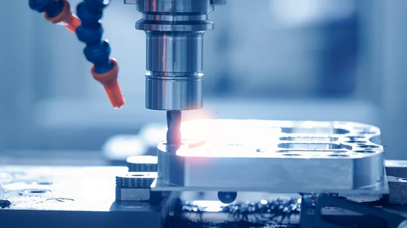
CNC Milling
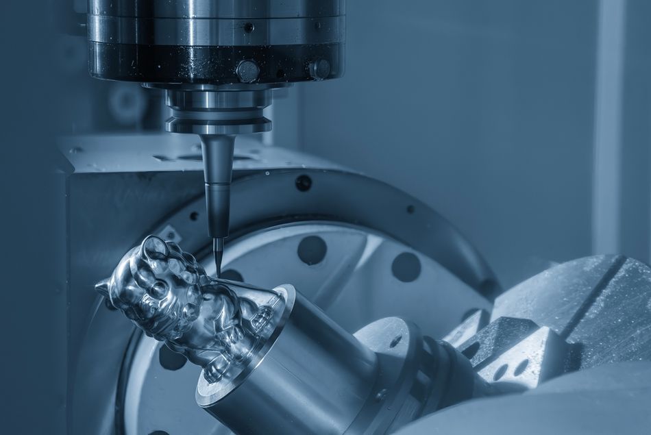
CNC milling removes material with a rotating, multi-point cutting tool while the workpiece remains fixed. Computer control governs toolpaths, spindle speeds, and feed rates, producing accurate 3D forms. Milling’s evolution from early NC equipment to modern multi-axis CNC systems has significantly expanded capability, precision, and automation.
Common machine configurations include:
Vertical mills for general-purpose work
Horizontal mills for improved chip evacuation and heavier cuts
Multi-axis platforms (3-axis, 4-axis, 5-axis) for undercuts and complex contours
Turret mills with movable heads
Gantry and bed-type systems for large components
A typical CAD-to-CAM workflow drives machine preparation, tool installation, fixturing, and coordinate setup. The operator then executes the G-code program and inspects the finished part, applying light deburring or finishing as needed. Milling provides excellent accuracy, repeatability, and surface quality across metals, plastics, and composites. Its limitations include programming complexity, setup time, and the higher cost of advanced multi-axis machinery. Despite these factors, milling remains foundational in aerospace structures, automotive powertrain components, electronics housings, heat sinks, and medical devices.
CNC Turning
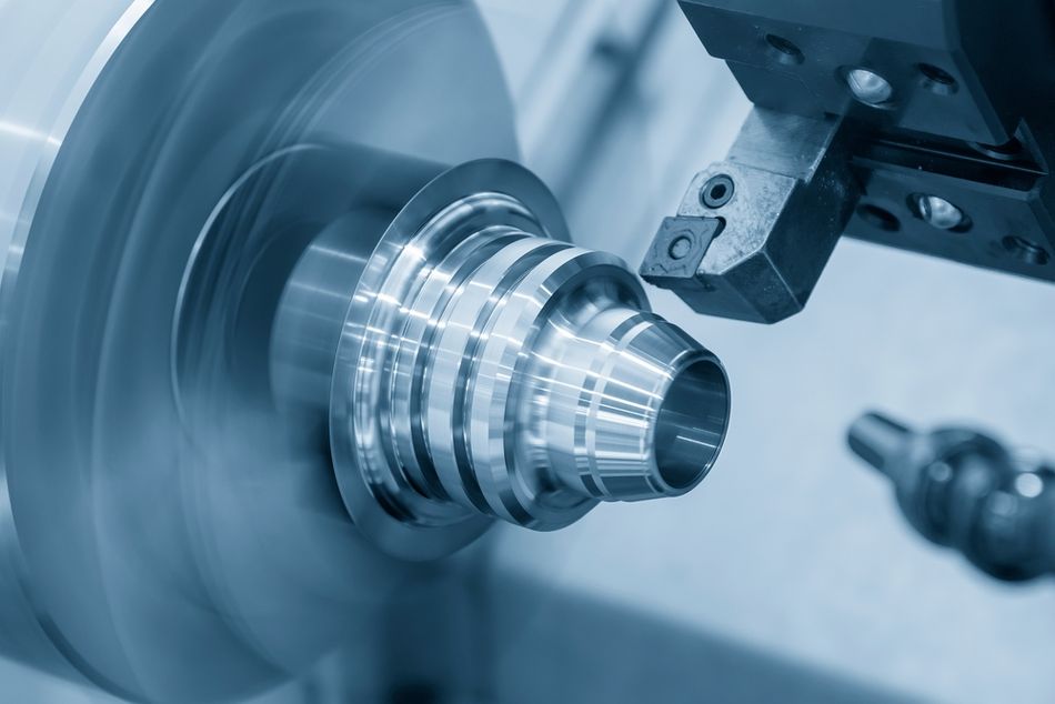
CNC turning shapes material by rotating the workpiece while a stationary cutting tool removes material along controlled axes. Many modern turning centers include live-tooling modules that perform drilling, tapping, or milling during the same setup.
Representative machine components include:
A headstock and chuck
A tailstock for supporting long parts
A tool turret for rapid indexing
Rigid slides and guideways
A coolant delivery system
Optional live-tooling spindles
Turning delivers fast cycle times, excellent roundness, and high-quality surfaces. It excels at shafts, bushings, pins, connectors, pulleys, and threaded components. Its inherent limitation is geometry: without live tooling, the process is restricted to rotationally symmetric features, though integrated milling functions broaden its reach.
Drilling and Boring
CNC drilling creates precise cylindrical holes in metals, plastics, composites, and electronics components. Equipment ranges from upright and radial-arm drill presses to gang and multi-spindle systems, and drilling integrates naturally with tapping, reaming, countersinking, and other hole-refinement steps.
Boring enlarges or improves an existing hole using a single-point cutting tool or boring bar. It produces superior roundness, diameter accuracy, and surface finish. Because boring removes material slowly and requires rigid setups, it is used for engine cylinders, aerospace housings, precision machinery frames, and heavy-equipment components. Drawbacks include slower removal rates and the need for specialized tooling.
Grinding
Grinding uses a rotating abrasive wheel to remove very small amounts of material, enabling extremely tight tolerances and fine surface finishes. It is particularly valuable for hardened steels, carbides, titanium, and other difficult materials.
Major grinding methods include:
Surface grinding for flat faces
Cylindrical grinding for external round surfaces
Centerless grinding for high-volume round parts
Internal grinding for bores
Profile grinding for molds and complex contours
Tool and cutter grinding for sharpening tools
Thread grinding for precision threaded features
Grinding achieves micrometer-level accuracy, minimal thermal distortion, and exceptional surface quality. Its limitations include slow material-removal rates and the need for specialized abrasive wheels. The process is essential for turbine components, crankshafts, gears, molds, dies, medical instruments, and precision tooling.
Broaching
Broaching removes material using a long, multi-tooth tool whose teeth increase in depth along its length, allowing the full profile to be cut in a single pass. It is ideal for producing keyways, splines, internal polygons, and other profiles in medium-to-high production volumes.
Common broaching approaches include:
Linear broaching for internal and external profiles
Rotary broaching for splines and polygonal shapes
Surface broaching for flat surfaces
Pull and push broaching depending on depth and material
Keyway and spline broaching for mechanical fits
Broaching offers excellent repeatability and surface quality but requires custom tooling and rigid machines, which limits its value for low-volume production. It is widely used in automotive transmissions, aerospace components, medical devices, and precision machinery.
Electrical Discharge Machining (EDM)
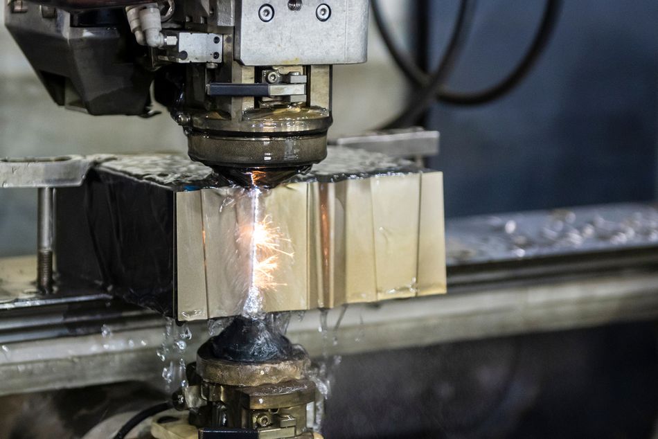
EDM uses controlled electrical discharges between an electrode and a conductive workpiece submerged in dielectric fluid. Wire EDM, which uses a continuously fed wire, cuts intricate contours without mechanical contact.
The method excels at delicate geometries, sharp internal corners, and small radii, and produces burr-free surfaces. Limitations include slower cutting speeds, restriction to conductive materials, and the formation of a thin recast layer on some metals. EDM is used for mold tooling, aerospace hardware, medical components, and high-precision mechanical parts.
Laser Beam Machining
Laser beam machining removes material by melting or vaporizing it with a concentrated laser beam. It is a non-contact process that minimizes heat-affected zones and supports fine features across metals, ceramics, polymers, and composites.
LBM is well suited for micro-features, thin sections, and components sensitive to thermal distortion. Its limitations include high capital cost and reduced efficiency with very thick or reflective materials. Applications include aerospace microstructures, electronic devices, automotive sensors, and medical components.
Water-Jet Machining
Water-jet machining erodes material using a high-velocity stream of water, often mixed with abrasive particles. Pure water jets handle softer materials, while abrasive jets cut metals, composites, glass, stone, and ceramics.
The process introduces no heat-affected zone, preserves material integrity, and produces smooth edges. It struggles with extremely thick or very hard sections. Water-jet machining is used in aerospace panels, industrial components, architectural materials, and food processing.
Other Processes and Emerging Techniques
Subtractive manufacturing also includes plunge EDM, plasma cutting, sawing, planing, and honing. Advances in multi-axis control, adaptive machining, real-time sensing, and AI-driven optimization continue to expand the efficiency and scope of subtractive processes across industries.
Recommended reading: CNC Machining Aluminum: A Guide for Digital Design and Hardware Engineers
Modern Trends and Hybrid Manufacturing
The landscape of subtractive manufacturing is evolving rapidly as digital control, automation, and hybrid workflows reshape expectations for productivity and flexibility. What was once a discipline defined by mechanical precision alone now incorporates sensing, data analytics, and additive–subtractive integration. These developments are changing how engineers design parts, plan operations, and connect machines within broader factory ecosystems.
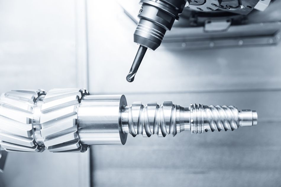
Multi-Axis and Intelligent Machining
Recent advances in CNC hardware enable coordinated motion across five or more axes, allowing complex geometries to be machined in a single setup. Traditional three-axis machines move only in X, Y, and Z, keeping the tool oriented vertically. Multi-axis systems add rotational axes—typically A, B, or C—that tilt or rotate the tool or the workpiece.[4] This extra freedom lets the cutter reach angled surfaces, undercuts, and compound contours without reclamping the part, improving accuracy and reducing cumulative alignment errors.
Five-axis machines typically use either a tilt-table design, where the workpiece rotates and tilts under a fixed spindle, or a swivel-head design, where the spindle itself pivots while the table remains stationary. Some advanced platforms combine both, enabling continuous simultaneous motion across all axes. Throughout machining, the controller calculates tool position and orientation in real time to maintain optimal cutting geometry, consistent chip load, and stable tool engagement.
Modern systems also incorporate extensive sensing and adaptive control. Sensors track forces, vibration, spindle load, and temperature, feeding data to algorithms that adjust feed rates, speeds, and tool angles automatically. Machine learning models predict chatter, optimize toolpaths, and flag emerging tool-wear or lubrication issues. Networked machines share data across the production floor, enabling remote monitoring, predictive maintenance, and ongoing process optimization. Together, these technologies allow multi-axis machining to deliver higher reliability, shorter cycle times, and cleaner surfaces on highly complex parts.
Hybrid Additive–Subtractive Machines
Hybrid platforms combine additive techniques with traditional cutting processes inside a single machine envelope. A part may be printed to near-net shape, then machined immediately to refine surfaces, threads, or interfaces. Conversely, cavities or channels can be printed directly into a workpiece and later finished with subtractive passes. Some systems integrate electrical discharge machining or allow functional elements—such as sensors or wiring—to be embedded during the build. This approach reduces setups, improves alignment between operations, and supports the creation of smart or highly customized components.
Automation and Robotics
Automation is becoming integral to modern machining environments. Robotic arms handle loading and unloading, manage workholding changes, and interface directly with machine tools. Coordinated inspection systems verify critical dimensions during or after machining, reducing manual intervention and downtime. Cloud-based scheduling platforms orchestrate job flow across multiple machines and maintain digital twins of equipment and processes. As these systems grow more interconnected, engineers must be familiar with data standards, sensor integration, and communication protocols such as MTConnect to ensure seamless interoperability across the manufacturing floor.
AI-Assisted CAM
AI-driven CAM tools are changing how machining programs are created.[5] Software such as Fusion 360 and Mastercam now uses machine learning to detect features, propose feeds and speeds, and generate efficient toolpaths with less manual input. Newer systems like CAM Assist can produce near-ready programs in seconds, reducing setup time and helping engineers focus on design rather than routine programming.
Applications of Subtractive Manufacturing
Subtractive manufacturing supports industries that require accuracy, repeatability, and materials with predictable mechanical performance. Its ability to hold tight tolerances, produce fine surface finishes, and work with a wide range of metals and engineered polymers makes it indispensable for safety-critical components, mechanical interfaces, and high-load structures. From aerospace brackets to surgical tools, subtractive processes enable parts that must perform reliably under extreme conditions, high temperatures, or continuous mechanical stress.
Industry | Applications | Typical Processes | Typical Materials |
Aerospace | Structural brackets, engine housings, landing gear components | 5-axis CNC milling, turning, grinding | Aluminum alloys, titanium, Inconel |
Automotive | Engine blocks, transmission parts, brake components | CNC milling, turning, broaching | Cast aluminum, alloy steels |
Medical | Implants, surgical tools, diagnostic equipment components | CNC milling, Swiss turning, grinding | Titanium alloys, stainless steel |
Electronics | Heat sinks, enclosures, connector housings | CNC milling, drilling, tapping | Aluminum, copper, engineering plastics |
Energy | Turbine parts, valve bodies, pump components | CNC milling, turning, EDM | Stainless steels, nickel alloys |
Industrial Machinery | Gears, shafts, precision bushings | Turning, gear cutting, grinding | Alloy steels, tool steels |
Marine | Propeller hubs, corrosion-resistant hardware | CNC milling, turning | Bronze, stainless steel |
Consumer Products | Housings, fixtures, appliance components | CNC milling, turning | ABS, polycarbonate, aluminum |
Recommended reading: Aerospace CNC Machining: How Precision Manufacturing Powers Modern Flight
Comparative Analysis: Subtractive vs Additive Manufacturing
Comparing subtractive and additive manufacturing begins with recognizing that each excels under different constraints. Subtractive methods can machine a broad range of materials, from metals and plastics to composites and wood, and they achieve tight tolerances, smooth surfaces, and highly repeatable geometries. Their precision makes them particularly effective for functional components that demand accurate fits, clean edges, or robust mechanical performance. The trade-off is that removing material generates chips and offcuts, and preparing a machine for a new job—selecting tools, programming toolpaths, and setting up fixturing—can take time, especially for low-volume production.
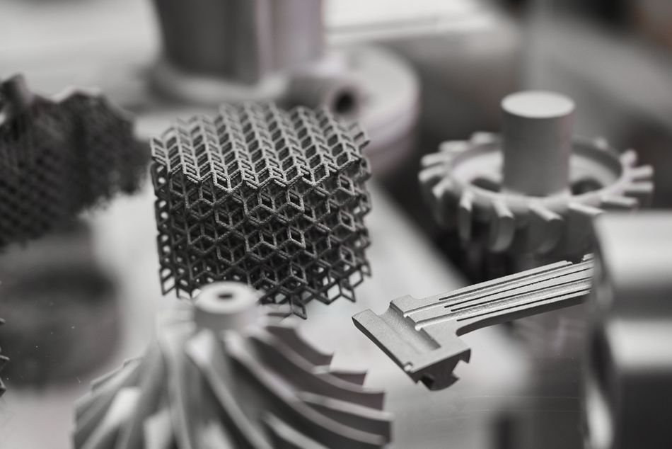
Additive manufacturing takes an opposite approach, constructing parts layer by layer instead of cutting them from solid stock. This enables intricate internal channels, organic shapes, and lightweight lattice structures that are difficult or impossible to machine directly. Waste is minimal and design freedom is high. However, printed parts often require secondary finishing to meet dimensional or surface-quality requirements, and the range of usable materials—particularly in metals—remains narrower than in machining. Additive processes also tend to be slower or more expensive for large parts or high-volume output.
In practice, many engineers now combine the two methods in hybrid workflows. A component might be printed to form complex internal passages or near-net-shape contours, then machined to refine critical surfaces, threaded features, or tight-tolerance interfaces. More advanced integrations pair additive processes with electrical discharge machining or embed sensors directly into printed layers. This merging of capabilities reflects a broader trend toward selecting the right tool for each part of the geometry rather than treating the two approaches as competitors.
Subtractive Manufacturing | Additive Manufacturing | |
Materials | Compatible with a wide range of metals, plastics, composites, and other engineering materials | Strongest support for polymers and specialty photopolymers; metal options exist but are fewer and often more costly |
Geometric Complexity | Well suited to straightforward and moderately complex parts; advanced multi-axis machines can handle intricate contours | Ideal for organic shapes, internal channels, lattice structures, and features difficult to machine conventionally |
Surface Finish and Tolerances | Capable of very smooth surfaces and tight dimensional control, suitable for precision fits and critical interfaces | Layer-by-layer construction results in visible texture; fine tolerances typically require secondary machining or polishing |
Material Use and Waste | Removes material from solid stock, producing chips and offcuts that may be recycled but still represent waste | Adds material only where needed, keeping waste extremely low and improving buy-to-fly ratios for many parts |
Setup and Production Speed | Longer setup due to tooling, fixturing, and programming; once prepared, excellent throughput for mid- to high-volume production | Rapid to begin printing, but slower for large parts or high-volume output; cost per part rises with scale |
Typical Applications | High-strength components, tight-tolerance assemblies, large parts, and production runs requiring repeatability | Rapid prototyping, customized components, complex internal features, and parts where geometry outweighs surface finish |
Sustainability and Waste Reduction in Subtractive Manufacturing
Sustainability is now a central concern in manufacturing, influencing both operational strategy and customer expectations. In subtractive processes such as CNC machining, the main sources of waste typically include excess material removed as scrap, high electrical demand during cutting, and time lost to inefficient setups or idle machines. Reducing these forms of waste not only minimizes environmental impact but can also lower production costs and improve overall equipment effectiveness.
Strategies for Sustainable Subtractive Manufacturing
Lean production and continuous improvement: Align output with actual demand, limit unnecessary inventory, and refine processes incrementally to eliminate non-value-added steps.
Sustainable materials and renewable energy: Incorporate recycled metals or bio-based plastics where performance allows, and reduce facility emissions by adopting solar, wind, or other renewable power sources.
Efficient material use: Implement closed-loop recycling of chips and offcuts, generate toolpaths that reduce unnecessary passes, and consider processes—such as laser or water-jet cutting—that create narrow kerfs and conserve material.
Process optimization: Tune spindle speeds, feed rates, and depths of cut to lower energy consumption; use multi-axis and high-speed machining to shorten cycle times; reduce idle states through job scheduling; and maintain equipment proactively to avoid inefficiencies.
Incentives and compliance: Government programs and tax credits can support investments in greener equipment, renewable energy, and process improvements, helping offset upfront costs while meeting regulatory expectations.
Conclusion
Subtractive manufacturing is an important group of technologies for producing the functional, high-strength components used across aerospace, automotive, electronics, and medical sectors. Processes such as milling, turning, drilling, grinding, broaching, EDM, and laser or water-jet machining offer the precision, surface quality, and material range that modern engineering depends on. Digital workflows—linking CAD models, CAM toolpaths, and G-code—drive increasingly capable multi-axis machines.
At the same time, sustainability efforts and hybrid additive–subtractive approaches are reducing waste and opening new design options. As factories adopt more automation, connected equipment, and intelligent controls, engineers and hardware designers will need a firm command of subtractive principles to build reliable, efficient, and forward-looking products.
FAQ
What is subtractive manufacturing?
Subtractive manufacturing removes material from solid stock using tools such as mills, drills, grinders, and lathes. It is valued for high precision, smooth finishes, and compatibility with a wide range of metals and engineering plastics.
How do subtractive processes differ from additive manufacturing processes?
Subtractive methods deliver tight tolerances but generate waste and require setup. Additive manufacturing processes build geometry layer by layer, often with a 3D printer or FDM system, offering design freedom with minimal scrap but narrower material options and frequent post-processing.
What materials are commonly used in machining processes?
Machining processes regularly handle aluminum alloys, steels, stainless steels, titanium, nickel alloys, composites, and engineering plastics. Material selection depends on strength, corrosion resistance, machinability, and application requirements.
When should I choose milling, turning, or grinding for metal parts?
Milling suits prismatic surfaces, turning is best for cylindrical metal parts, and grinding is ideal for hard materials or ultra-fine finishes. Geometry and tolerances determine the best fit.
How do modern manufacturing technologies improve efficiency?
CNC systems, sensors, robotics, and cloud-connected controllers streamline workflows, reduce errors, and support predictive maintenance. These manufacturing technologies also enable hybrid workflows where printing and machining operate together.
What other manufacturing methods or manufacturing techniques support part production?
Shops may combine casting, molding, forming, laser cutting, or water-jet cutting with machining to match volume, cost, and geometry needs. These complementary manufacturing techniques broaden the range of shapes and materials that can be produced.
How does hybrid manufacturing work?
Hybrid systems can print near-net shapes using binder jetting or other additive methods, then refine critical features through milling, turning, or grinding. This approach reduces setups and unites complex geometry with precise machined surfaces.
How can sustainability be improved in subtractive workflows?
Manufacturers reduce waste by recycling chips, optimizing toolpaths, tuning feeds and speeds for lower energy use, using recycled materials, and incorporating renewably powered equipment. Streamlined setups and reduced idle time further decrease environmental impact.
What is the future direction of manufacturing?
Expect greater integration of subtractive and additive methods, smarter adaptive controls, increased use of 3D printer platforms for early prototypes, and expanded automation across all manufacturing methods. As demands for accuracy grow, machining and additive technologies will continue to converge.
References
[1] Regalla SP. Additive and subtractive manufacturing. In3D Printed Smart Sensors and Energy Harvesting Devices: Concepts, fabrication and applications 2024 Dec 1 (pp. 3-1). Bristol, UK: IOP Publishing. Available from: https://iopscience.iop.org/book/edit/978-0-7503-5351-9/chapter/bk978-0-7503-5351-9ch3
[2] Carlsson B. The development and use of machine tools in historical perspective. Journal of Economic Behavior & Organization. 1984 Mar 1;5(1):91-114. https://doi.org/10.1016/0167-2681(84)90028-3
[3] Schmitt AM, Miller E, Engelmann B, Batres R, Schmitt J. G-code evaluation in cnc milling to predict energy consumption through machine learning. Advances in Industrial and Manufacturing Engineering. 2024 May 1;8:100140. https://doi.org/10.1016/j.aime.2024.100140
[4] Rahman M. Modeling and measurement of multi-axis machine tools to improve positioning accuracy in a software way. University of Oulu; 2004 Jun 4. https://oulurepo.oulu.fi/handle/10024/35464
[5] Hexagon AB. AI-powered CAM. Available from: https://hexagon.com/solutions/ai-powered-cam. Accessed 2025 Nov 24.
in this article
1. The Basics of Subtractive Manufacturing2. Core Subtractive Processes3. Modern Trends and Hybrid Manufacturing4. Applications of Subtractive Manufacturing5. Comparative Analysis: Subtractive vs Additive Manufacturing6. Sustainability and Waste Reduction in Subtractive Manufacturing7. Conclusion8. FAQ9. References