Infill 3D Printing: All You Need to Know
The internal structure of a 3D printed part can be adjusted via 3D printer infill settings, giving users control over variables like part weight and strength, print time, and material usage.

Last updated on 10 Oct, 2023. 11 minutes read
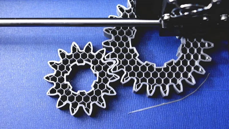
3D printed gears with honeycomb infill
You wouldn’t know just by looking at them, but the majority of 3D printed parts are not completely solid on the inside. In fact, most are at least 50 percent hollow. That’s because printing with full density uses up a large amount of material and takes a long time. Furthermore, it doesn’t often make the part significantly stronger.
But printed parts don’t just have arbitrary cavities inside them. Rather, they contain a precise patterned structure known as infill. The infill can be a grid pattern, a triangle pattern, or something more complex like concentric rings, and these patterns can have varying degrees of density: there can be lots of empty space between the material, or there can be very little or even none at all. Users can therefore choose between different infill patterns and infill densities to suit the build.
It’s important to know about 3D printing infill when designing and fabricating parts. But the great thing is that the slicer software generates the infill automatically; it doesn’t have to be designed manually using CAD software. That means users only have to tweak a few simple parameters to radically adjust the internal structure of their prints.
This article goes over the basics of 3D printing infill, looking at how infill works and providing the best infill settings for common scenarios.
What is Infill in 3D Printing?
No matter their shape or size, FDM 3D printed parts can be seen as comprising two parts: shells and infill. These are like the skin and bones of a printed object: shells (or perimeters) are the surface or walls of the part, and infill is what lies within.
Infill is the internal structure of the part, and it can have a range of patterns and densities, which can be adjusted in the slicer software and applied automatically to the g-code (the coded instructions sent to the 3D printer in order to commence a print). Infill has a big impact on how a part turns out. For example, a CAD design for a 3D printed cube could be printed with several different types of infill: it could be fully solid, fully hollow, or have an arrangement of lines or other shapes within it. These different versions of the cube would have different weights and levels of strength, and would not all print in the same amount of time.
Crucially, infill only applies to the parts of the object that appear as “solid” on the CAD design. For example, it is possible to design a part with an internal geometry, such as a cube-shaped mold with a star-shaped cavity inside. In such a case, the cavity will be empty space regardless of the infill settings; infill will apply only to the areas between the cavity and the outer walls of the cube.
Users can adjust a few parameters regarding shells, such as choosing the thickness of the outer wall and whether there should be extra top layers or bottom layers. But infill settings provide a greater degree of control over the print job and the printed part.
Recommended reading: What is 3D Printing: A Comprehensive Guide to its Engineering Principles and Applications
What is Infill Density?
Users can choose their level of infill density, from fully hollow (a part comprising just the shell) to fully dense. A higher infill density means more material is used within the part, resulting in higher strength.[1] However, denser parts are also heavier, take longer to print, and have higher material costs.
Infill density is expressed as a percentage and is sometimes referred to as infill percentage. 0% infill density is a fully hollow part, while 100% is a fully solid part. Visual parts like figurines and display prototypes tend to have a very low infill density, because they do not need to be strong. Functional parts, on the other hand, are usually more than 50% dense and sometimes even fully dense, as they typically do require a higher degree of strength.
Infill density can also be used to control the rigidity of flexible prints made from soft filaments like TPU and TPE. Low-density parts made of such materials will be very stretchy, while high-density parts will be firmer.
In some slicers, users can adjust a parameter called infill line distance. For infill patterns like lines and grid, this has the same effect as adjusting density, as it determines the amount of space between each extruded line of plastic.
Recommended Infill Density Settings
Infill density can be adjusted depending on the purpose of the 3D printed part. Visual parts, lightweight parts, and test parts should have a low density, while functional parts should have a higher density. For flexible prints, density correlates with stiffness, so a lower value helps to increase stretchiness.
Visual-only prints: 0–15% infill density
Standard prints: 15–50% infill density
Functional prints: 50–100% infill density
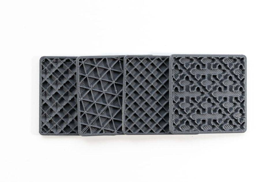
What is Infill Pattern?
An FDM 3D printer deposits material in successive 2D layers. However, the printhead can lay down the solid (or partially solid) areas of each layer in various ways: in straight lines, in concentric rings, and in other ways. It can use 2D patterns like a sequence of squares or triangles, or it can use 3D shapes like tilted, interconnected cubes that span multiple layers.
Like infill density, infill pattern can have a big impact on the physical properties of the printed part. For example, some patterns are stronger than others: triangles are more stable than squares,[2] while 3D patterns like interconnected cubes tend to be the strongest infill patterns in terms of possessing strength across all directions. Patterns can also be dynamic: some are designed to have a stronger arrangement in vulnerable areas of the part and a more lightweight arrangement in stable areas, helping to maintain part strength while conserving material consumption.
When selecting an infill pattern, it is important to consider whether the part will have to bear loads, and if so, in what direction those loads will travel. Some patterns are better at handling forces in the vertical direction, while others are better in the horizontal.
At present, Cura offers 14 default infill patterns,[3] PrusaSlicer offers 16, and Slic3r provides seven. The patterns can also be modified by adjusting other printing parameters.
Infill patterns can be grouped into four general categories:
Quick 2D infills: Consistent pattern across each layer; low strength but optimized for fast printing. Examples: Lines (rectilinear), zig-zag
Strong 2D infills: Consistent pattern across each layer; high strength but can take longer to print. Examples: Triangles, honeycomb, tri-hexagon
Strong 3D infills: Pattern passes through X, Y and Z axes; high strength in all directions. Examples: Cubic, octet, gyroid
Flexible infills: Pattern passes through X, Y and Z axes; intentionally low strength for increased flexibility. Examples: Concentric, cross, cross 3D
A comprehensive guide to individual infill patterns can be found in our guide to Cura infill patterns. This guide covers the many patterns available in Ultimaker’s Cura slicing software.
Recommended reading: Cura infill patterns: What they are and when to use them
Recommended Infill Pattern Settings
Different infill patterns suit different applications. Some are best for quick prototypes, some provide exceptional strength, while others increase flexibility. Although users will have their own preferences, the following list provides suggestions for particular printing scenarios.
Visual-only parts: Lines
Parts requiring horizontal strength: Tri-hexagon
Parts requiring vertical strength: Grid
Parts requiring strength in all directions: Most 3D infill patterns
Parts requiring strength while also conserving material usage and print time: Cubic subdivision
Parts requiring strength when printed at 100% density: Concentric
Flexible parts: Cross 3D
Other Infill Settings and Considerations
There are a handful of adjustable infill parameters beyond infill density and infill pattern. The most important of these parameters are:
Infill line direction: This parameter sets the angle of the infill pattern, which is typically 45° by default, as this provides strength and speed benefits over printing parallel or perpendicular to the shell. However, a parallel or perpendicular direction may be preferable in some situations, e.g. transparent parts where the infill plays an aesthetic role.
Infill XY offset: Infill pattern is typically applied relative to the center of the print. The infill XY offset parameter, available in Cura, allows for shifting of the pattern along the X and Y axes. It is useful for low-density infill, where the placement of each line is particularly important.
Infill layer thickness: This parameter sets the layer height of the infill and can be adjusted independently of the overall layer height (though it must be in multiples of the overall layer height). Since infill is not visible, it often makes sense to use a greater layer thickness to decrease printing time.
Infill overlap: The infill lines intersect with the inner shells at various points. Infill overlap (expressed as a percentage or a measurement) determines how much the infill and shells overlap. A greater amount of overlap improves bonding, but infill lines can sometimes become visible through the outer walls.
Advanced Infill Techniques
Gradual Infill
Gradual infill is a technique that involves varying the infill density throughout the height of a 3D printed part. This approach is useful for parts without load-bearing requirements, as it allows the lower areas of a print to have less dense infill — reducing total weight and material usage — while printing more dense areas at the top to support the upper layers.
One limitation of gradual infill is that it can make parts top-heavy and potentially unbalanced due to the greater density in the upper regions.
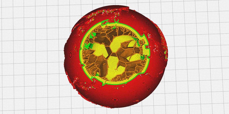
Adaptive Infill
Adaptive infill is a technique that involves automatically adjusting the infill density and pattern based on the geometry of a 3D printed part. This approach allows for the optimization of strength, weight, and print time by intelligently placing denser infill in areas that require more support or strength, while using less dense infill in areas where it is not as critical.
Adaptive infill works by analyzing the geometry of the part and identifying regions that require additional support or reinforcement. The slicing software then generates an infill structure with varying density (and/or pattern), depending on the specific needs of each region. This results in a more efficient use of material and reduced print time, as denser infill is only used where it is necessary for the part's performance.
One example of adaptive infill is PrusaSlicer’s “Adaptive cubic infill” pattern. This pattern is like the standard cubic infill pattern, but the cubes vary in size (therefore varying the density) depending on their distance to the nearest wall. The largest cubes (and lowest density) will be found in the center of the print.
Lightning Infill
In 2021, Ultimaker released the “Lightning infill” feature in Cura version 4.12. Unlike standard infill patterns, this form of infill took a radically different approach to internal support structures, saving printing time and material usage while maintaining strength in key areas.
Lightning is ultimately a form of adaptive infill, but looks unlike any other type of infill pattern. It works a bit like tree supports on the exterior of a print, generating internal supports (somewhat resembling lightning bolts) that support material only where necessary. Some internal areas of the print can therefore be completely hollow, while others will have dense regions of “lightning.”
According to Ultimaker, “a model printed using lightning infill can use up to 90% less material than a solid model and often results in a reduction of 50% or more when compared to using another infill option at the same infill percentage.”
Troubleshooting Infill Issues
Weak infill is a common issue that can occur during the 3D printing process, manifesting as stringy, under-extruded, or incomplete infill structures. Weak infill can compromise the strength and performance of the printed part.
It can be helpful to observe the infill of the part at various points during the printing process to ensure it is printing as expected. Unless a translucent filament is being used, the infill will no longer be visible once the part is complete and the shells are enclosing it.
Possible ways to fix weak infill include:
Adjust print speed: Printing at a speed that is too high can cause the material to extrude unevenly or incompletely, resulting in weak infill. (Note that some slicer profiles will stipulate a faster infill printing speed by default.) To resolve this issue, reduce the infill print speed in your slicing software settings and perform a test print to ensure proper extrusion.
Use simpler pattern: Complex infill patterns like cubic or adaptive patterns are harder to print, so using a simpler pattern like rectilinear can help mitigate weak infill and other related issues.
Adjust extrusion settings: If the extrusion multiplier or flow rate is set too low, the printer may not deposit enough material to fill the infill structure properly. To resolve this issue, check your slicing software settings and adjust the extrusion multiplier or flow rate as needed.
Check nozzle: A partially clogged nozzle can restrict the flow of material, leading to underextrusion and infill gaps. To fix this problem, clean the nozzle using a nozzle cleaning tool or by performing a cold pull to remove any debris or filament residue.
Check filament: Poor quality or inconsistent diameter filament can cause underextrusion and infill gaps. Ensure that you are using high-quality filament with a consistent diameter, and check the filament spool for any tangles or knots that may restrict the flow of material.
Consider avoiding flexible filament: Although they are not often interchangeable, rigid filament typically prints better and more consistent infill than flexible filament.
Conclusion
As we have seen, infill is a powerful tool at the 3D printer user’s disposal. Without having to adjust their 3D model at all, users can make significant changes to part strength, part weight, part flexibility, and print speed.
For beginners, adjusting infill density is perhaps the most intuitive way to optimize printing time, material consumption, and the mechanical properties of the printed parts. But getting to grips with different infill patterns (and more advanced settings) gives a much greater degree of control over the printing process and part performance.
Frequently Asked Questions
1. What is the purpose of infill in 3D printing?
Infill provides the internal structure of a 3D printed object, affecting its strength, weight, and print time. It helps support the object's structure and resist deformation under load.
2. How does infill density affect the strength and weight of a 3D printed part?
Higher infill densities generally result in stronger parts, as more material is present to support the object's structure. However, increasing infill density also increases the weight of the part, as more material is used to fill the interior volume.
3. What are some common infill patterns, and how do they affect the properties of a 3D printed part?
Common infill patterns include rectilinear, honeycomb, gyroid, and triangular. Each pattern has its own advantages and disadvantages, depending on the specific requirements of the printed part, such as strength, weight, and print time.
4. What are gradual and adaptive infill techniques, and how can they be used to optimize 3D printed parts?
Gradual infill involves varying the infill density throughout the height of a printed part, while adaptive infill automatically adjusts the infill density and pattern based on the geometry of the part. Both techniques can help optimize strength, weight, and print time by strategically placing denser infill in areas that require more support or strength.
References
[1] Johnson GA, French JJ. Evaluation of infill effect on mechanical properties of consumer 3D printing materials. Advances in Technology Innovation. 2018 Oct 1;3(4):179.
[2] Aloyaydi B, Sivasankaran S, Mustafa A. Investigation of infill-patterns on mechanical response of 3D printed poly-lactic-acid. Polymer Testing. 2020 Jul;87:106557.
[3] Infill settings [Internet]. Ultimaker Support. Ultimaker; 2020 [cited 2022 Apr 6]. Available from: https://support.ultimaker.com/hc/en-us/articles/360012607079-Infill-settings