How to Make a 3D Model for Printing
Most beginners start their 3D printing journey by downloading 3D models from the internet. But knowing how to make a 3D model for printing using CAD software opens up a world of possibilities.

Last updated on 05 Apr, 2024. 11 minutes read

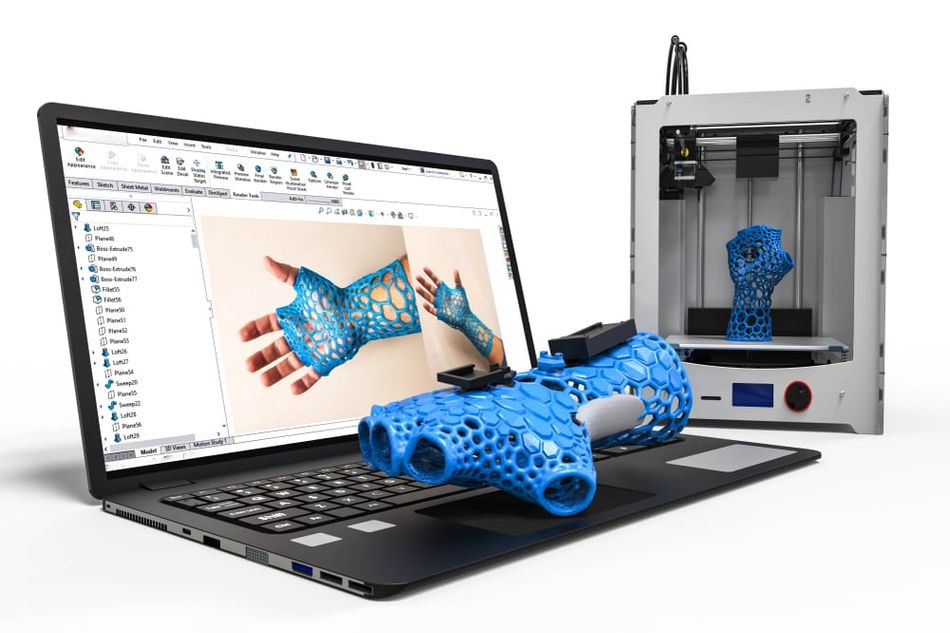
CAD software is used to create 3D printable models
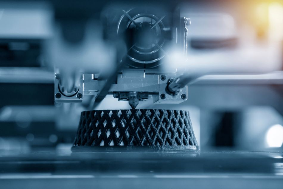
3D models are the foundation of 3D printing. Every print begins with a digital model designed using special software, which is then converted or “sliced” into instructions that can be understood by the 3D printer. The printer then turns that digital model into a real object.
Knowing how to make a 3D model for printing is very important, since there is no other way to create printed objects. Unlike a milling machine or lathe, for example, you can't control a 3D printer with your hands without asking the computer for help. 3D printers can only work from digital instructions.
This article goes over the basics of how to make a 3D model for printing. It discusses the best CAD software and other 3D modeling software for 3D printing, basic design guidelines for 3D printing, and the best slicers for turning 3D models into printable code. It looks mainly at the relationship between 3D modeling and 3D printing, so readers looking for a full introduction to 3D design should look for tutorials for their specific software.
Design Software for 3D Printing
3D models for printing are made using computer-aided design (CAD) software or other types of 3D modeling software. These applications are powerful tools that allow for the creation of very complex designs.
Knowing how to make a 3D model for printing requires more than just artistic talent. After all, not every 3D model is suitable for 3D printing: a perfectly rendered model of an airplane might look great on screen, but its protruding wings and ultra-fine propeller blades might be very difficult to extrude using molten plastic. 3D designers must therefore be realistic about the possibilities and limitations of the printing process.
Different 3D design tools have different uses. For example, CAD software is used to design parts for digital manufacturing technologies, including 3D printing and CNC machining, in fields such as aerospace, healthcare, and consumer products. 3D models for on-screen applications such as 3D animation and video games are typically made using 3D computer graphics software, not CAD.
Types of CAD
Engineers and designers use computer-aided design (CAD) to digitally design physical objects. This is what makes CAD special compared to other types of 3D design: it is focused on creating models that adhere to the rules of physics and which can therefore become a physical object.
Most CAD tools use one of two paradigms: direct modeling or parametric modeling. However, many applications offer both options. Direct modeling, which involves adjusting the 3D geometry (by dragging and dropping, stretching, etc.), is faster, simpler, and typically used during early-stage design. Parametric modeling is a mathematical and “history-based” paradigm where parts are designed by determining features and constraints. Changes are made step by step in a way that conforms with the original constraints.
Some professional-oriented CAD programs are expensive, with most packages now sold with a yearly license rather than a perpetual license. However, there are many excellent free CAD and other 3D modeling programs suitable for 3D printing, such as those listed below.
Recommended reading: How to find free STL files
Free CAD and 3D Modeling Software for 3D Printing
TinkerCAD: Beginner-friendly and browser-based (it does not need to be downloaded onto a computer), TinkerCAD allows for the drag-and-drop of 3D shapes, saving files to the cloud. The online 3D software is intuitive and a great starting point for CAD novices. As such, it is slightly limited in scope but nonetheless suitable for a variety of printable models.
SketchUp Free: Trimble’s free, browser-based version of SketchUp contains the basic tools for 3D modeling. It uses cloud storage, which can be helpful when accessing projects across multiple devices. One advantage of SketchUp is its integration with 3D Warehouse, which contains a large library of free-to-download models.
Fusion 360: Autodesk’s powerful CAD application is available on a free license for non-professional users. Some features are omitted, but the software contains enough tools for the design of mechanical engineering parts, via direct or parametric design. Though well-designed and fairly intuitive, Fusion 360 is recommended for more advanced users rather than absolute beginners. It is more suited to 3D printing than Maya, one of Autodesk’s other CAD applications.
Onshape: Though the full version of Onshape is aimed at professional and industrial product designers, Onshape Free is a great browser-based tool for 3D printing hobbyists. One caveat is that your designs automatically become public; only users of the paid version can keep their models private.
FreeCAD: Popular 3D modeling software FreeCAD is a versatile and free 3D design package suitable for a range of 3D printing applications, including architecture and product design. Notable features include an advanced geometry engine, a parametric environment, and compatibility with a wide range of file formats.
Blender: A free and open-source tool used by animators and 3D printer users alike, Blender is a mesh-based direct modeling application favored for its artistic tools. It is not CAD software, but it can be used to design 3D models with organic shapes such as figurines and gaming pieces, while its 3D Print Toolbox ensures designs are watertight. It is also less intuitive than some other applications.[1]
The (Extreme) Basics of CAD
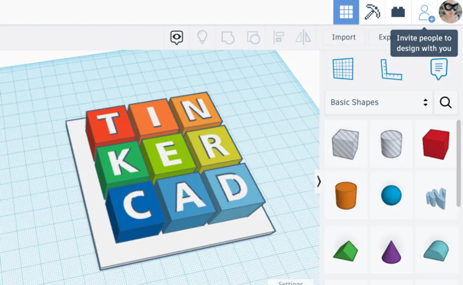
Making a 3D model for printing requires familiarity with your software of choice, and users can look for written and video tutorials to discover how their CAD application works. However, here we describe a very basic workflow using TinkerCAD, which is one of the more popular applications for beginner 3D printer users.
First, access the TinkerCAD website and sign in or create an account if you haven't already done so. Then, create a new project by selecting "Create New Design." Next, add basic shapes to the workplane using the toolbar. Shapes such as cubes, spheres, cylinders, and pyramids are readily available.
Once you have added the shapes, manipulate them by clicking and dragging to resize, rotate, and position them as desired. Use the toolbar to fine-tune dimensions as needed. After positioning the shapes, combine them using tools like "Group" to merge shapes together or "Hole" to subtract one shape from another. This allows you to create more complex forms and structures. After finalizing your design, use the "Inspect" tool to ensure that it is solid and free of errors that could affect printability.
Once you are satisfied with your model, export it in the desired file format, typically .STL, compatible with your 3D printer. Load this file into your 3D printing software (slicer) and prepare to execute the print.
Design for 3D Printing
Learning how to manipulate CAD software in order to create complex 3D shapes takes time, and every application works in its own unique way. 3D design is also trickier than 2D design. Not only is there an extra dimension to consider, but designs must always have manifold geometries (they must be “real” 3D shapes with fully joined-up edges, faces, and vertices). Many 3D printing errors stem from non-manifold CAD models, which are not 3D printable since they do not represent objects that can exist in physical space.
3D printer users need to remember that their 3D models won’t just exist on the screen. They will be turned into physical 3D objects, and designers must therefore create their 3D models with the FDM 3D printing process in mind — even if that means making compromises (such as removing overhangs, thickening up fine features, or adding a wide base).
In the world of professional design and engineering, this printing-focused approach to design is called Design for Additive Manufacturing (DfAM). But the rules of 3D printing design apply equally to industrial designers and hobbyists.
Bridging
Bridging is when a 3D model features a suspended horizontal section supported by two vertical sections, like a raised bridge supported by two abutments. Bridging can cause issues for 3D printers: since the horizontal section is not supported from below, it can sag or even collapse entirely.
The issue can be solved in different ways. Keeping the bridge less than 5 mm should prevent sagging, otherwise a support structure may be needed underneath it. Support structures are generated automatically by the slicing software (they do not need to be added to the CAD model), printed along with the rest of the part, then cut or broken away manually.
Overhangs
Overhangs are a little bit like bridges. They are protruding horizontal sections, but they are connected on just one side to a vertical section (rather than on each side). An example of overhangs would be the two horizontal “wings” of an upright “T” shape.
Like bridges, overhangs can cause issues if they are not supported from underneath by support structures, and can therefore sag or collapse.[2] Generally, overhangs will support themselves at an angle of up to 45°. The “wings” of an upright “Y” shape, for example, can be supported by the vertical stem. If the angle is greater than 45°, supports should be used.
Recommended reading: Cura support settings, from angles to Z distance
Corners
When designing your own model using CAD software, it’s easy to create boxy shapes with sharp corners and edges. But 3D printer nozzles are round, so the lines of material they extrude cannot produce perfectly right-angled corners; designers should keep this in mind, especially when designing components that are meant to fit snugly together. (A similar limitation applies when designing for CNC machining, in which the cutting tool is round).
Fortunately, rounded corners can be a blessing as well as a curse. Adding fileted (rounded) interior or external corners to the 3D model can improve strength and reduce stress, especially on bridges and overhangs.
Round Surfaces
Because the FDM printing process prints in layers, it is often possible to see “layer lines” where the different layers meet. These lines are especially pronounced — sometimes critically so — when printing round surfaces (on a 3D printed ball, for instance). This issue is sometimes called the “stair-stepping” effect, because the noticeable jumps between layers resemble a staircase.
When making a 3D model with round surfaces, designers should know that the printed surface may look much more jagged than the digital surface. One solution is to use a very low layer height when slicing the model, so the steps are smaller and less visible; another is to use a 3D printing service to get the model printed using Stereolithography (SLA); another is to treat the printed part with post-processing techniques like sanding and smoothing.
Holes
One advantage of 3D printing is the ability to design holes directly into the part, rather than drilling them out later. However, designers should bear in mind that FDM printers can’t always replicate the exact specifications of the CAD model.
Issues can arise with vertical axis holes (e.g. a hole in the top face of a part). This is because when the nozzle pushes down on material on the hole perimeter, it squishes it towards the hole aperture and therefore reduces the diameter of the hole. This can be a problem if the hole is meant to accommodate a fastener, for example. Holes may therefore need to be slightly oversized, with trial and error often required.
First Layers
The first layer of a print is the most important, because good bed adhesion prevents the part slipping during printing. One of the best ways to ensure good bed adhesion is to design a 3D model with a wide and flat base; more points of contact with the build surface means greater adhesion and stability.
Unfortunately, this can sometimes mean compromising on part design. Printing a ball, for instance, is difficult because the part of the ball that touches the build surface is just one small point. But a half-ball (a dome) with a flat base would print much more successfully. Note that parts can also be split into sections (e.g. two separate domes) then assembled using glue or fasteners to make the complete object.
Layer Orientation
One of the most important things to remember about 3D printing is that printed parts are anisotropic.[3] That is, they are stronger in one direction than another. So when designing functional parts that require some degree of strength, it is important to consider the printing and layer orientation.
In short, printed parts are weak where the layers meet. This means that a printed part has low tensile strength along the Z-axis (you could more easily break the part by pulling it top to bottom rather than side to side). Parts are strongest in planes parallel to the build surface.
A practical example would be a thin printed shelf designed to support heavy objects. The shelf will be strongest if printed “flat” or parallel to the build surface, but weaker if printed upright or perpendicular to the build surface.
Slicing Software
Once the 3D model is complete, the CAD software can export the design as an STL file. However, the 3D printer cannot process the STL file as it is; it needs to receive instructions about the part in the form of G-code. Knowing how to make a model for 3D printing therefore requires a basic understanding of slicing software.
The core functionality of a slicer is to convert a 3D model into machine-readable instructions. Specifically, it translates the 3D model into a sequence of flat layers and determines the appropriate linear movements of the 3D printer for creating those layers. The slicer also sets a number of printing parameters (printing temperature, infill pattern, support structures, and much more) and writes those settings into the G-code.
As with 3D design software, there are several free slicing applications for turning 3D models into 3D printer instructions.
Free Slicers for 3D Printing
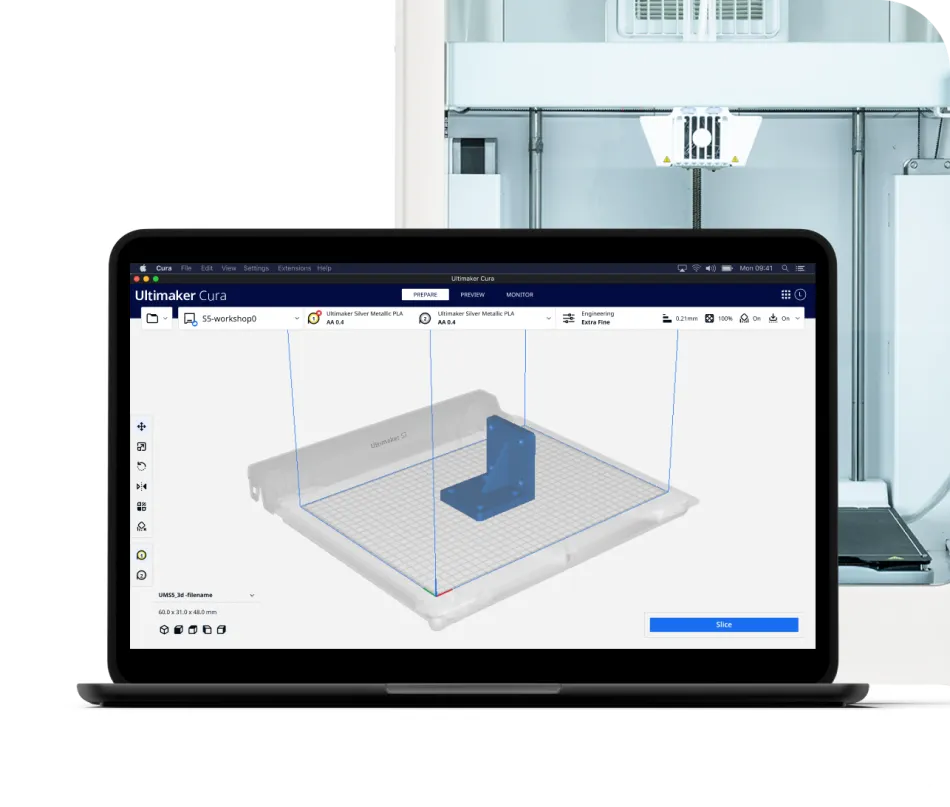
Cura: Ultimaker’s free-to-use and open-source slicer is popular with professionals and hobbyists alike. Offering a simple workflow and downloadable plugins, Cura divides the slicing process into three stages: Prepare, Preview, and Monitor. Helpful tools include print time and filament usage estimates.
Slic3r: Developed and maintained by a group of RepRap community members, the open-source Slic3r is regularly updated by its active community of open-source developers. With features like auto-repair and multi-extruder slicing, Slic3r is a good tool for those interested in pushing the boundaries of their 3D printer.
OctoPrint: Primarily a tool for remote 3D printer management (including webcam monitoring of prints), the free OctoPrint software also offers slicing features.
Conclusion
Figuring out how to make a 3D model for printing requires three general areas of understanding: familiarity with your CAD software of choice, an understanding of 3D printing design constraints, and a grasp of the slicing process. Once these foundations are in place, making your own models will become a fast and natural process that results in functional, error-free printed parts.
Frequently Asked Questions (FAQs)
How do I ensure my 3D model is printable?
To ensure printability, consider wall thickness, overhangs, support structures, and model orientation. Use mesh analysis and repair tools to identify and fix geometry issues. Choose the right material and printing technology for your project.
How can I optimize my 3D model for faster printing?
To optimize for faster printing, reduce model complexity, minimize support structures, and use a lower infill density. Adjust print settings, such as layer height and print speed, to balance quality and efficiency.
What are the limitations of 3D printing technology?
Limitations of 3D printing include material restrictions, limited build volume, and the need for post-processing. 3D printing can be time-consuming and expensive, especially for large or complex parts. Understand these limitations and design your models accordingly.
How can I improve the surface quality of my 3D printed parts?
To improve surface quality, use post-processing techniques like sanding, polishing, or vapor smoothing. The choice of technique depends on the material and desired finish. Adjust print settings, such as layer height and print speed, to achieve better surface quality.
References
[1] Junk S, Kuen C. Review of open source and freeware CAD systems for use with 3D-printing. Procedia CIRP. 2016 Jan 1;50:430-5.
[2] Cacace S, Cristiani E, Rocchi L. A level set based method for fixing overhangs in 3D printing. Applied Mathematical Modelling. 2017 Apr 1;44:446-55.
[3] Baker AM, Mccoy JO, Majumdar BS, Rumley-Ouellette BR, Wahry JA, Marchi AN, Bernardin JD, Spernjak DU. Measurement and modelling of thermal and mechanical anisotropy of parts additively manufactured using fused deposition modelling (FDM). InProceedings of the 11th International Workshop on Structural Health Monitoring, Stanford, CA, USA 2017 Sep (pp. 12-14).