How to Find Thevenin Voltage: A Complete Practical Guide for Engineers
A practical guide for engineers to find Thevenin voltage in DC and AC circuits and apply it in real-world circuits for power systems, sensors, amplifiers, and efficient load analysis.

22 Dec, 2025. 14 minutes read

Key Takeaways
The Thevenin voltage is the open-circuit voltage measured across a pair of terminals when the load is removed; it represents the driving capability of the source network.
To find the Thevenin voltage, remove the load resistor, determine the open-circuit voltage, then calculate the Thevenin resistance by deactivating independent sources and recombining resistances.
Thevenin’s theorem applies to linear circuits containing resistors, capacitors, inductors, and dependent sources. In AC analysis, resistances are replaced by impedances, and phasor methods are used to measure the open-circuit voltage.
Thevenin’s equivalent circuit allows engineers to simplify complex networks, analyze voltage behavior under load, and design for maximum power transfer, which occurs when the load resistance equals the Thevenin resistance of the source network.
- Practical measurement involves measuring the open-circuit voltage and then measuring the voltage and current with a known load to compute Rth from the slope of the I-V curve.
Introduction
Modern electrical and electronic systems often contain complex networks of sources and passive components. In practice, engineers rarely need to analyze every internal element of such a network. Instead, the key requirement is to understand how the network behaves when a load is connected. This is why reducing a complex circuit to a simpler, equivalent form is a fundamental skill in electrical engineering and is essential for knowing how to find the Thevenin voltage across any terminals efficiently.
Thevenin’s theorem provides a systematic way to simplify any linear two-terminal network into an equivalent circuit consisting of a single voltage source in series with a resistance. At the core of this method is the Thevenin voltage, which represents the open-circuit voltage seen by the load. Understanding how to find Thevenin voltage allows engineers to predict load behavior, evaluate voltage regulation, and perform reliable circuit analysis without repeatedly solving the full network.
This article explains how to find the Thevenin voltage using step-by-step methods based on open-circuit analysis, followed by determining the associated Thevenin resistance. It also covers practical measurement techniques, simulation-based verification, and real-world applications such as load regulation, impedance matching, and AC circuit analysis. The guide is intended for digital design engineers, hardware engineers, and electronics engineering students who require a reliable and efficient approach to know how to find the Thevenin voltage seen by a load in complex circuits.
Background: What is Thevenin’s theorem?
Thevenin’s theorem states that any linear, two-terminal electrical network can be replaced by an equivalent circuit consisting of a single voltage source connected in series with a resistance. This equivalent produces the same terminal voltage–current relationship as the original network, regardless of the internal complexity of the circuit.
The diagram shown below shows Thevenin's equivalent circuit:
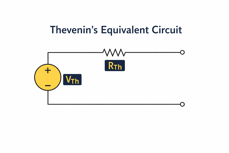
Mathematically, the theorem is valid for networks that satisfy linearity (superposition applies) and bilaterality (the circuit response is independent of the direction of current). Networks composed of resistors, capacitors, inductors, linear dependent sources, and ideal independent voltage or current sources comply with these conditions. Non-linear components (e.g., diodes, transistors) do not satisfy the theorem, but Thevenin equivalents can still be applied to their linearized small-signal models around a defined operating point.
Thevenin Voltage and Resistance
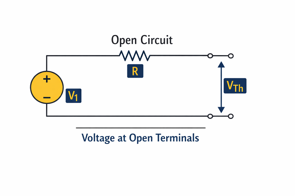
The Thevenin voltage Vth is defined as the open-circuit voltage across the terminals—meaning the voltage measured when no load is connected. This open-circuit condition is critical because it ensures that no current flows through the terminals, eliminating any voltage drop caused by the internal resistance of the network. In practice, if the load is disconnected from terminals A and B and the terminal voltage is measured with an ideal voltmeter, the measured value is Vth.
It is important to distinguish between the source voltage inside a circuit and the Thevenin voltage at the terminals. In many practical circuits, internal resistances and network topology cause the terminal voltage to differ from the original supply voltage. Thevenin voltage, therefore, reflects the effective output voltage of the entire network, not simply the value of an individual source.
The Thevenin equivalent resistance Rth is the equivalent resistance seen by the load when all independent sources are deactivated. Independent voltage sources are replaced by short circuits, and independent current sources by open circuits. The resistance seen at the terminals is then calculated using standard circuit reduction techniques such as series–parallel combinations or Y-delta transformations. Once Vth and Rth are determined, the entire original network can be replaced by a single voltage source (Vth) in series with resistance (Rth) for the purpose of analyzing load behavior.
Recommended Reading: Source Transformation in Electrical Circuit Analysis: Thevenin–Norton Equivalence & Circuit Simplification
Why Use Thevenin’s Theorem?
Thevenin’s equivalent is essential because it:
Simplifies analysis of complex networks; instead of solving a full circuit repeatedly for different load values, the Thevenin equivalent is computed once and reused.
Helps in impedance matching. At low frequencies and in lumped-element models, matching the load resistance to the Thevenin resistance helps control voltage levels and power delivery. For transmission lines, characteristic impedance matching is treated separately.
Enables maximum power transfer analysis. Maximum power is transferred when the load resistance equals the Thevenin resistance, a principle widely used in sensor interfaces, audio systems, and energy-constrained designs.
Provides insight into voltage droop and regulation. By modelling the source network as Vth in series with Rth, you can predict how the output voltage droops as load current increases.
Finding the Thevenin Voltage Vth
Finding the Thevenin voltage follows a structured process that is consistent across DC and AC linear circuits. While the mathematical tools may vary depending on circuit complexity, the underlying logic remains the same: determine the voltage that appears at the output terminals when the load is not influencing the network.
Step 1: Identify the Load Terminals
The first step is to identify the two terminals across which you want to find the Thevenin voltage. Label them A and B. Remove the load resistor (or whatever component you plan to connect). The goal is to determine the voltage that would appear across these open terminals. Establish a clear reference polarity at the terminals to avoid sign errors later in the analysis.
Step 2: Remove the Load Element
Disconnect the load resistor or load circuit entirely from the terminals. This step creates the condition required to find the Thevenin voltage. The goal is to analyze the source network alone, without any current drawn by an external load. At this stage, the terminals should be open, meaning no current flows out of the network.
Step 3: Establish the Open-Circuit Condition
With the load removed, enforce the open-circuit condition explicitly in your analysis. This means setting the terminal current to zero. This step is conceptually important because it ensures that no internal voltage drops occur due to load current. The resulting terminal voltage reflects the true driving potential of the network.
Step 4: Calculate the Voltage across the Open Terminals.
Apply appropriate circuit analysis techniques—such as Ohm’s law, voltage division, nodal analysis, mesh analysis, or superposition—to compute the voltage between the open terminals (Voc). The choice of method depends on circuit topology and complexity. In AC circuits, this step is performed using complex impedances and phasor quantities. The calculated voltage under open-circuit conditions is the Thevenin voltage Vth.
Finding Thevenin Voltage in Simple DC Circuits
The process of finding the Thevenin voltage becomes most intuitive when applied first to simple DC circuits. These cases help build a clear understanding of the open-circuit concept before extending the method to more complex networks.
Single-Source, Single-Loop Circuits
A single-source, single-loop circuit typically consists of one independent voltage source and a set of resistors connected in series. This is the simplest case for finding the Thevenin voltage and is often encountered in basic power and biasing circuits.
To begin, the output terminals are identified, and the load resistor is removed, leaving an open circuit at the terminals. Because the circuit contains only one loop, the open-circuit voltage can usually be found using the voltage division principle. The total series resistance determines how the source voltage is distributed across the resistors.
The step-by-step process involves calculating the total resistance of the loop, determining the current flowing in the loop, and then finding the voltage across the resistor or combination of resistors connected to the output terminals. Since no current flows through the open terminals, the calculated voltage directly represents the Thevenin voltage.
Multiple Resistors with One Voltage Source
Circuits with one independent voltage source but multiple resistors arranged in series and parallel combinations are common in practical designs.
After removing the load, the internal resistor network is simplified using series–parallel reduction techniques. Choosing a consistent reference node is important, especially when the output terminals are not directly across a single resistor.
A typical worked approach involves reducing the resistor network step by step, calculating the voltage at the output node relative to the reference node, and assigning the correct polarity. The resulting node-to-node voltage under open-circuit conditions is the Thevenin voltage.
Circuits with Multiple Independent Sources
When a circuit contains multiple independent voltage or current sources, the Thevenin voltage can no longer be found using simple voltage division alone. In such cases, superposition is used.
The superposition method involves considering one independent source at a time while keeping all other independent sources deactivated. Voltage sources are replaced by short circuits, and current sources are replaced by open circuits during each step. For each active source, the open-circuit voltage at the output terminals is calculated.
Each source’s contribution to the terminal voltage is determined separately. Once all individual contributions are found, they are algebraically summed to obtain the total open-circuit voltage.
Finding Thevenin Voltage Using the Node-Voltage Method
The node-voltage method is a systematic and reliable approach for determining the Thevenin voltage, particularly in circuits with multiple nodes, current sources, or non-trivial interconnections.
This method aligns naturally with Thevenin’s definition because the Thevenin voltage is the open-circuit voltage measured between two nodes. By directly solving for node voltages with respect to a reference node, nodal analysis provides an efficient path to Vth.
To apply the method, the load across the output terminals is first removed to enforce the open-circuit condition. A reference (ground) node is then selected, and Kirchhoff’s Current Law is applied at each remaining node. Currents are expressed in terms of node voltages using Ohm’s law (or impedances in AC circuits), resulting in a set of linear equations.
Once the node voltages are solved, the Thevenin voltage is simply the voltage difference between the two output nodes, with polarity determined by the chosen reference directions.
Finding Thevenin Voltage Using Mesh Analysis
Mesh analysis is an effective method for finding the Thevenin voltage in planar circuits that are dominated by voltage sources and contain a limited number of loops. It is particularly well-suited to networks where currents flow in clearly defined meshes and where the output terminals lie across elements within a loop, rather than at complex node intersections.
The method is based on defining mesh currents for each independent loop in the circuit. When determining the Thevenin voltage, the load connected to the output terminals is first removed to establish the open-circuit condition. Mesh currents are then assigned with consistent directions, typically clockwise, to simplify sign conventions.
Kirchhoff’s Voltage Law (KVL) is applied around each mesh to form a set of linear equations. Each equation expresses the sum of voltage rises and drops in a loop, written in terms of mesh currents and element values. Shared elements between meshes are handled by expressing the voltage drop as a function of the difference between the corresponding mesh currents.
Once the mesh equations are solved, the Thevenin voltage is obtained by calculating the voltage across the open output terminals, using the appropriate mesh current and element relationships. The polarity of the result follows from the assumed mesh current directions and the defined terminal reference.
Compared with the node-voltage method, mesh analysis is often more efficient for circuits with fewer loops than nodes and with multiple voltage sources. However, it becomes less convenient when current sources or non-planar structures are present.
Finding Thevenin Voltage in AC Circuits (Phasor Domain)
In AC circuit analysis, Thevenin’s theorem extends naturally into the phasor domain, allowing complex networks operating at a fixed frequency to be replaced by an equivalent voltage source and impedance. The fundamental definition remains unchanged: the Thevenin voltage is the open-circuit voltage measured at the output terminals, but it is now expressed as a complex phasor rather than a real-valued DC quantity.
The primary difference between DC and AC Thevenin analysis lies in the treatment of circuit elements. Resistors are replaced by complex impedances, capacitors by 1/(jωC), and inductors by jωL. As a result, the Thevenin voltage generally has both magnitude and phase, reflecting not only how large the voltage is but also how it is phase-shifted relative to the source.
To find the Thevenin voltage in an AC circuit, the load is removed, and the circuit is analyzed using phasor techniques such as nodal or mesh analysis. All voltages and currents are represented as complex quantities, and Kirchhoff’s laws are applied in the frequency domain. The voltage difference across the open terminals is then taken as Vth.
Care must be taken when interpreting results, particularly with respect to RMS versus peak values. In most engineering contexts, phasor voltages are conventionally expressed in RMS form.
Mixing RMS and peak values can lead to scaling errors if not handled consistently.
Thevenin equivalents in AC analysis are especially important in power systems, analog signal chains, and frequency-response studies, where impedance interactions determine voltage levels, power transfer, and signal integrity.
Recommended Reading: KCL Circuit Analysis: Advanced Engineering Methods & Best Practices 2025
Special Considerations When Finding Thevenin Voltage
When applying the standard steps to find the Thevenin voltage, there are several important considerations that engineers should keep in mind to avoid common analytical errors.
First, all independent sources remain active when calculating the Thevenin voltage. The open-circuit condition applies only to the load at the output terminals. Independent voltage sources must not be shorted, and independent current sources must not be opened during the calculation of Vth. Source deactivation is used only when determining the Thevenin resistance.
Second, circuits containing dependent sources require no special removal or deactivation when finding Vth. Dependent sources are part of the network’s behavior and must always remain active, since their values depend on circuit variables. The open-circuit voltage should be calculated using standard analysis methods while keeping all dependent sources intact.
Third, circuits with multiple independent sources can still be analyzed directly to find the Thevenin voltage. Each source contributes to the final value of Vth, and the total voltage is obtained by combining these contributions consistently.
Practical Measurement Techniques
Using a Multimeter
In real circuits, the most direct way to determine the Thevenin voltage is by measuring the open-circuit voltage at the output terminals. To do this, the load connected across terminals A–B is disconnected so that no current flows. The voltage measured across the terminals using a high-impedance voltmeter is, by definition, the Thevenin voltage VthV_{th}Vth.
This method is effective because modern digital multimeters draw negligible current and therefore do not significantly disturb the circuit. Care should be taken to ensure that the circuit remains in its normal operating condition after the load is removed, especially in feedback-driven or bias-sensitive designs.
SPICE Simulation and Digital Design Tools
In simulation environments such as LTspice, PSpice, and Cadence OrCAD, the Thevenin voltage is obtained by simply removing the load from the output terminals and evaluating the resulting open-circuit node voltage through a DC operating-point analysis. Because the circuit is already represented in a solved electrical model, the terminal voltage is directly available without additional setup or approximation.
This approach is commonly used during circuit design and verification to observe expected voltage levels at interfaces, sources, or analog inputs under ideal open-circuit conditions.
Practical Engineering Applications of Thevenin Voltage
The concept of Thevenin voltage plays a central role in how engineers interpret and model real electrical systems. By representing a complex network through its open-circuit terminal voltage, engineers gain a clear and consistent reference for expected voltage behavior before considering load interaction.
Power System Modeling
In power systems, Thevenin voltage is used to represent the effective source voltage seen at a bus or node. During steady-state and contingency analysis, engineers evaluate the open-circuit voltage to establish baseline operating conditions. This voltage-centric view simplifies system studies and allows comparisons across different network configurations without exposing internal complexity.
Sensor and Measurement Circuits
Sensor outputs and measurement front ends are often characterized by their Thevenin voltage. The open-circuit voltage defines the sensor’s nominal output under ideal conditions and serves as a reference when assessing measurement accuracy. This is especially important in low-level signal acquisition, where knowing the intended voltage level helps distinguish between sensor behavior and loading effects introduced by measurement hardware.
Amplifier Input Modeling
In analog and mixed-signal design, the Thevenin voltage is used to model the signal source driving an amplifier input. The open-circuit voltage represents the maximum available input signal, allowing designers to verify gain structure, biasing, and dynamic range. This abstraction enables clean separation between source behavior and amplifier response during early-stage design.
Load Interaction and Efficiency Considerations
Although full efficiency analysis involves additional parameters, Thevenin voltage alone provides insight into how a source behaves as loading increases. Comparing the open-circuit voltage to the loaded terminal voltage helps engineers assess voltage stability and determine whether a source is suitable for a given application from a voltage-delivery standpoint.
Fault Analysis and System Diagnostics
In fault analysis, deviations in expected Thevenin voltage can indicate abnormal operating conditions such as supply degradation, wiring faults, or unintended loading. Engineers use changes in open-circuit voltage as diagnostic signals when troubleshooting complex systems.
Why Practicing Engineers Rely on Thevenin Equivalents
Practicing engineers rely on Thevenin voltage because it reduces complexity without sacrificing accuracy. It provides a clear, measurable, and simulation-friendly way to describe how a circuit presents voltage to the outside world, making it an essential tool across design, analysis, and validation workflows.
Common Pitfalls and Troubleshooting Tips
- If the load remains connected while determining the Thevenin voltage, the measured value will reflect the loaded terminal voltage rather than the true source voltage.
- When dependent sources are present, the equivalent voltage cannot be obtained by simply deactivating all sources. In such cases, the open-circuit voltage should be determined directly from circuit analysis or simulation, ensuring the dependent elements remain functional.
- Thevenin’s theorem applies only to linear networks. Circuits containing diodes, transistors, or other non-linear devices require linearization around an operating point or the use of small-signal models before the equivalent voltage can be meaningfully defined.
- In AC analysis, the equivalent voltage is represented as a phasor. Both magnitude and phase must be handled carefully, particularly when converting between rectangular and polar forms, to avoid incorrect voltage interpretation.
- When measuring the Thevenin voltage using a multimeter, ensure the meter has sufficiently high input impedance so it does not load the circuit. Any unintended loading can reduce the measured voltage and lead to inaccurate results.
Conclusion
Thevenin voltage provides a clear and practical way to understand how a circuit presents voltage at its terminals, independent of the connected load. By removing the load and evaluating the terminal voltage under open-circuit conditions, engineers obtain the Thevenin voltage, which represents the maximum available output voltage of the network. This voltage-centric view allows a complex original circuit to be treated as a single, equivalent source from the outside.
Focusing on Thevenin voltage is particularly valuable in design, measurement, and verification tasks where voltage levels, stability, and signal integrity are the primary concerns. Whether working with analog signals, digital interfaces, or reference voltages, accurately determining Vth enables engineers to predict circuit behavior before loading effects are introduced. When applied to linear networks with proper measurement or simulation techniques, the Thevenin voltage becomes a reliable and widely applicable analysis tool.
Frequently Asked Questions
Q1: What is the physical meaning of the Thevenin voltage?
The Thevenin voltage Vth is the voltage that appears at the terminals of a network when no load is connected. It represents the internal electromotive force of the network. You can imagine it as the output of an ideal voltage source that drives the network’s internal resistance. It is found by removing the load and measuring or calculating the open-circuit voltage.
Q2: How do I find the Thevenin voltage in circuits with capacitors or inductors?
In AC circuits, replace resistors with impedances. The steps remain the same: remove the load and compute the open-circuit phasor voltage.
Q3: Can Thevenin’s theorem be applied to non-linear circuits?
Thevenin’s theorem applies only to linear circuits. Non-linear elements violate the principle of superposition. However, for small-signal analysis, you can linearise a non-linear circuit around an operating point and apply Thevenin’s theorem to the linearised model. This is common in transistor amplifier design.
Q4: Why is my measured Thevenin voltage lower than expected?
Common causes include unintended loading by the measurement instrument, incomplete removal of the load, or incorrect reference connections. Always ensure true open-circuit conditions and use a voltmeter with sufficiently high input impedance to avoid measurement error.
Q5: Can Thevenin voltage be applied to circuits with dependent sources?
Yes. Dependent sources remain active when determining the Thevenin voltage. As long as the circuit is linear, the open-circuit terminal voltage is valid and correctly represents the Thevenin voltage.
Q6: What is the difference between Thevenin's and Norton's theorems?
Thevenin and Norton equivalents describe the same linear circuit using two different source models. Thevenin’s equivalent represents the circuit as an ideal voltage source in series with an internal resistance, while Norton’s equivalent represents it as an ideal current source in parallel with the same resistance. Both models produce identical terminal voltage–current behaviour.
References
[1] “Thévenin’s theorem,” Wikipedia, last updated Dec. 2025. [Online]. Available: Link. [Accessed: 12-Dec-2025].
[2] “Open-circuit voltage,” Wikipedia, last updated Nov. 2025. [Online]. Available: Link. [Accessed: 14-Dec-2025].
[3] “Thevenin and Norton Equivalent Circuits,” Cadence Resources, Cadence Design Systems, 2020. [Online]. Available: Link. [Accessed: 15-Dec-2025].
[4] “Understanding Thevenin’s Theorem: Equivalent Circuits,” Advanced PCB Design Blog, Cadence Design Systems, 2019. [Online]. Available: Link. [Accessed: 13-Dec-2025].
[5] “Thevenin’s Theorem Tutorial | Thevenin’s Equivalent Circuit,” Electrical Academia, 2015. [Online]. Available: Link. [Accessed: 15-Dec-2025].
in this article
1. Key Takeaways2. Introduction3. Background: What is Thevenin’s theorem?4. Finding the Thevenin Voltage Vth5. Finding Thevenin Voltage in Simple DC Circuits6. Finding Thevenin Voltage Using the Node-Voltage Method7. Finding Thevenin Voltage Using Mesh Analysis8. Finding Thevenin Voltage in AC Circuits (Phasor Domain)9. Special Considerations When Finding Thevenin Voltage10. Practical Measurement Techniques11. Practical Engineering Applications of Thevenin Voltage12. Common Pitfalls and Troubleshooting Tips13. Conclusion14. Frequently Asked Questions15. References