Duplexer vs Diplexer: A Technical Guide to RF Signal Management Components
Have you considered how modern communication systems, like GSM networks, satellite communications, and broadcasting, manage multiple signals with precision? RF diplexers and duplexers make seamless signal sharing and optimal performance possible. Let’s explore the technology in this article.

06 Dec, 2024. 16 minutes read
Duplexer vs Diplexer: Understanding RF Signal Management Components
Managing RF (Radio Frequency) signals is critical to modern communication systems. Tools like duplexers, diplexers, combiners, and splitters are essential for ensuring that signals are transmitted and received efficiently without interference. RF signals are electromagnetic waves that operate in the radio spectrum, ranging from 3 KHz to 300 GHz [1]. They are the backbone of wireless communication, broadcasting, satellite systems, radar systems, and more. As technology advances, managing these signals effectively has become more challenging and important. Signal management involves separating, combining, and routing RF signals so they reach the right destination without losing quality. This process allows:
- Devices to transmit and receive signals at the same time.
- Multiple devices share the same antenna without interference.
- Different frequencies are to be handled without performance issues.
Duplexer vs Diplexer: What’s the Difference?
Two important tools for managing RF signals are the duplexer and the diplexer. While their names sound similar, their functions are quite different:
- A duplexer allows a device to transmit and receive signals at the same time using the same antenna. It isolates the two paths so the signals don’t interfere with each other. This is especially important in systems like LTE, where both uplink and downlink signals are handled simultaneously over different bands.
- A diplexer, on the other hand, is used to combine or separate signals that operate on different frequency bands (like UHF and VHF). This allows these signals to share the same transmission line or antenna, ensuring minimal interference.
Both devices are crucial in systems like GSM networks, TV broadcasting, ham radios, satellite communication, and base stations. Using RF filters and routing mechanisms helps keep communication smooth and interference-free, whether it’s for everyday use or complex industrial setups.
Understanding RF Diplexer
What Is an RF Diplexer?
An RF Diplexer (link for image purpose only) is an essential component in radio frequency (RF) systems that allows two or more signals to share the same transmission medium, such as a single antenna, without interfering with each other. In simpler terms, it is a device that separates or combines signals that operate at different frequency bands, such as UHF (Ultra High Frequency) and VHF (Very High Frequency). Diplexers are crucial in many communication systems where multiple frequency bands are in use but need to be transmitted or received simultaneously.
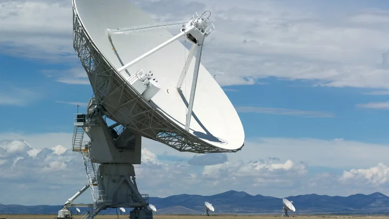
In applications like TV broadcasting, GSM networks [2], and satellite communications, signals at different frequency ranges must coexist on the same transmission medium. Without a diplexer, there would be significant interference between these signals, making reliable transmission and reception impossible. Essentially, diplexers act as three-port devices that allow different signals to travel without overlapping or causing distortion.
For example, a television station may need to transmit both UHF and VHF signals from a single antenna. A diplexer will separate these signals, ensuring that each band is transmitted without interference. Similarly, in a GSM network, a diplexer can separate the uplink and downlink signals to allow them to share the same antenna while maintaining clear communication.
Key Components of a Diplexer
The core functionality of an RF diplexer lies in its filters, which are used to allow certain frequency bands to pass through while blocking others. These filters are typically bandpass filters, low-pass filters, and high-pass filters, each serving a different role in ensuring that only the desired signals are allowed to pass while blocking undesired frequencies.
Bandpass Filters
- Function: A bandpass filter allows signals within a specific frequency range to pass through, while blocking frequencies outside of that range.
- Role in a Diplexer: Bandpass filters are used in diplexers to ensure that only the required frequency band (such as UHF or VHF) passes through to one port while blocking the VHF frequencies.
- Example: In satellite communication systems, a bandpass filter might allow the signal in the 1-2 GHz range to pass through while blocking signals outside that range.
Low-Pass Filters
- Function: A low-pass filter permits low-frequency signals to pass through while attenuating (reducing the strength of) higher-frequency signals.
- Role in a Diplexer: In diplexers, low-pass filters are used to isolate and allow lower frequencies (like VHF) to pass through. They block higher frequencies to ensure the diplexer only routes the desired low-frequency signals.
- Example: A low-pass filter might be used in a VHF signal path to ensure that only VHF signals (30-300 MHz) pass while blocking higher frequencies, such as UHF signals.
High-Pass Filters
- Function: A high-pass filter allows high-frequency signals to pass through while blocking lower-frequency signals.
- Role in a Diplexer: High-pass filters in diplexers ensure that higher-frequency signals (such as UHF) pass through while preventing lower-frequency signals from interfering.
- Example: In a diplexer designed for satellite communication, a high-pass filter might allow frequencies above 1 GHz to pass through while blocking those below that threshold.
Each of these filters works together to ensure the signals that need to be separated (such as UHF and VHF) can share the same transmission medium (such as an antenna) without overlapping or causing interference. By using different filters in conjunction, a diplexer can effectively manage multiple frequency bands on a single antenna or transmission line.
Applications of Diplexers
RF diplexers are found in numerous applications across communication systems. Their ability to separate or combine signals based on frequency makes them versatile tools for managing RF signals efficiently. Below are some of the key areas where diplexers are commonly used:
TV Transmitters
- Function: In television broadcasting, UHF and VHF signals are typically transmitted over the same antenna. A diplexer is used to separate these frequency bands so that each can be transmitted without interference.
- Example: A TV station broadcasting both UHF and VHF channels would use a diplexer to combine the signals at the transmitter end, allowing both frequency bands to be transmitted via a single antenna without causing overlap or distortion.
GSM Networks
- Function: In GSM (Global System for Mobile Communications) networks, base stations often need to handle multiple frequency bands simultaneously. For example, a base station might operate on both the 900 MHz and 1800 MHz bands. A diplexer allows these two signals to be separated, so they can be sent through a common antenna system without interfering with each other.
- Example: In a GSM transceiver system, the uplink (from mobile to base station) and downlink (from base station to mobile) signals often use different frequency bands. A diplexer separates these signals so that both can share the same antenna.
Satellite Communications
- Function: Diplexers are crucial in satellite communication systems where multiple frequency bands are often used for transmission and reception. For instance, the uplink frequency from a ground station might be different from the downlink frequency, and a diplexer helps in separating these signals.
- Example: In satellite systems, a diplexer separates the transmission and reception frequencies to ensure that they do not interfere with each other, even though they are transmitted over the same antenna system.
By ensuring that signals from different frequency bands do not interfere, diplexers enable more efficient use of the available communication channels and antenna systems.
How Does a Diplexer Work?
At its core, a diplexer uses a combination of filters to separate or combine signals operating at different frequency bands. The filters work based on the principle that each signal is composed of a specific frequency range, and by using the right type of filter (low-pass, high-pass, or bandpass), a diplexer can selectively route signals to or from their respective paths.
Signal Separation or Combination
When two signals with different frequency ranges need to travel through a single transmission medium (such as an antenna or coaxial cable), the diplexer separates the signals based on their frequencies. The low-pass filter will block higher frequencies, allowing only lower frequencies (like VHF) to pass, while the high-pass filter will allow only higher frequencies (like UHF) to pass. A bandpass filter is used to isolate a specific frequency range for the signal.
For example, if a diplexer is used for a TV broadcast, it may separate the VHF and UHF signals, ensuring they both travel independently through the antenna system, even though they share the same path.
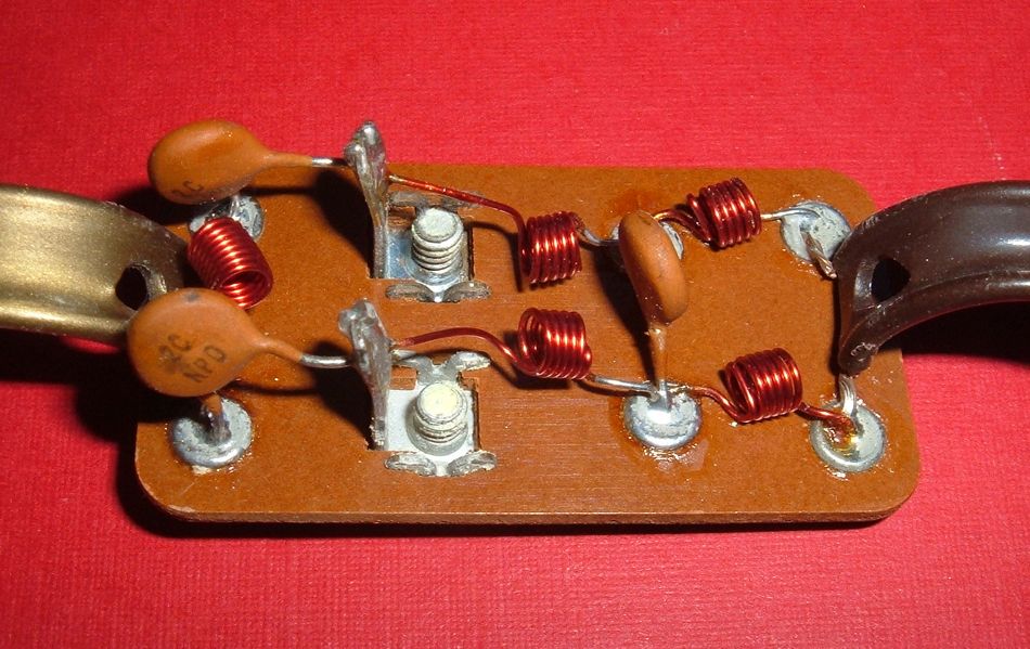
Role of Coaxial Cables and Connectors
The physical components of a diplexer circuit include coaxial cables, capacitors, and connectors, all of which help in maintaining signal integrity and minimizing losses. Coaxial cables are particularly useful in RF systems because they have a low loss and help preserve the strength and quality of the signal as it travels through the diplexer.
For example, if a diplexer is used for a TV broadcast, it may separate the VHF and UHF signals, ensuring they both travel independently through the antenna system, even though they share the same path.
Minimizing Signal Loss
One of the critical considerations in diplexer design is minimizing signal loss. Microstrip circuits and well-designed filters help ensure that the signal quality is maintained, and that attenuation is minimized. Attenuation refers to the loss of signal strength as it passes through a component, and minimizing attenuation is crucial in high-performance RF systems.
Additionally, PCB (Printed Circuit Board) RF components are often used in diplexers for creating compact, efficient designs that minimize losses and improve signal integrity.
In summary, a diplexer works by using a combination of filters — high-pass, low-pass, and bandpass — to ensure that signals at different frequency bands can either be separated or combined without interference. The entire system is supported by components such as capacitors, coaxial cables, and connectors, all of which help to maintain the quality and integrity of the RF signal as it passes through the diplexer.
Suggested Readings: PCBA vs PCB: The foundation of modern-day electronics
Understanding RF Duplexer
What Is an RF Duplexer?
An RF duplexer [link for image purpose only) is a critical component in modern communication systems, particularly in full-duplex systems, where both transmission and reception occur simultaneously. The main function of a duplexer is to allow a single antenna to be used for both transmitting and receiving radio frequency (RF) signals, without the transmitted signal interfering with the received signal. This ability is especially important in systems like LTE networks, where bandwidth optimization is crucial for efficient communication.
In basic terms, a duplexer separates the incoming and outgoing signals, ensuring that they follow different paths while using the same antenna. It does this by isolating the two signals in both time and frequency domains, which is crucial for systems like cellular communication, radar, and amateur (ham) radio. A duplexer’s role in maintaining signal impedance matching is critical for reducing signal loss and ensuring high-quality transmission.
Key Functions of a Duplexer
- Signal Isolation: The duplexer isolates the transmit and receive signals so they can share the same antenna without interference.
- Full-Duplex Communication: A duplexer facilitates simultaneous two-way communication by separating the transmission and reception signals, allowing them to travel at the same time without overlapping.
- Frequency Management: It allows different frequency bands (e.g., UHF, VHF) to be used by transmit and receive paths while keeping the signals from interacting with each other.
How Does a Duplexer Work?
A duplexer is designed to split and isolate signals based on their frequency characteristics, ensuring that transmit and receive paths do not interfere with each other. It achieves this through a combination of circulators and filters, specifically tuned to the frequencies used for transmission and reception.
- Circulators: These are non-reciprocal devices (meaning they only transmit signals in one direction) used in the duplexer to direct signals to the appropriate paths. A circulator sends the transmit signal to the antenna and routes the receive signal from the antenna to the receiver. The circulator ensures that the transmitted signal doesn’t leak back into the receiver path, and the received signal is properly routed to the receiver.
- Example: A circulator will send the transmit signal from a base station to the antenna, while simultaneously directing the receive signal from the antenna to the receiver of the base station.
- Cavity Filters: These are resonant filters used in duplexers to further isolate transmit and receive signals. Filters are designed to allow certain frequencies to pass through while rejecting others. The cavity filter ensures that only signals within a particular frequency range pass through, effectively blocking any unwanted signals.
- Example: A cavity filter will allow uplink signals (transmitted by the user) to pass, while blocking downlink signals (received by the user) from reaching the transmitter.
- Bandpass Filters: These filters ensure that only signals within a specific frequency range are transmitted or received. The bandpass filter can separate the uplink and downlink by their respective frequencies. The transmit and receive bands are typically designed to be narrow, so that the signals do not interfere with each other [3].
- Example: In GSM communication, uplink and downlink frequencies are carefully managed using filters to ensure that signals do not overlap.
- Transmission Lines: These are cables (often coaxial cables) used to connect the duplexer to the antenna, transmitter, and receiver. Transmission lines must be carefully matched to avoid signal losses or reflections.
- Example: Coaxial cables used in duplexer setups ensure the power transfer from the transmitter to the antenna is efficient, while maintaining signal quality when the received signal comes back to the receiver.
Suggested Readings: Difference between Active and Passive Filters?
The Duplexer’s Role in the Communication Chain
- Transmit Path: The signal from the transmitter is directed to the antenna, typically using a circulator and bandpass filter to isolate the transmission frequency.
- Receive Path: The antenna picks up the signal from the environment and directs it through the circulator and cavity filter to the receiver. The duplexer ensures that the signal going to the receiver is free of any transmit signals, preserving the quality of the received data.
In short, the duplexer ensures that the transmitted signal does not interfere with the received signal, enabling simultaneous full-duplex communication with minimal interference.
Understanding RF Splitters
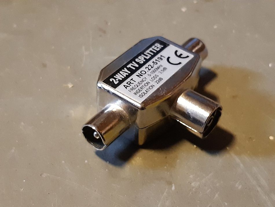
Belling-Lee RF splitter. Credits: Wikimedia
What Is an RF Splitter?
An RF Splitter is a device used to divide a single RF signal into multiple outputs, each carrying a fraction of the original signal’s power. RF splitters are typically used in situations where one signal needs to be distributed to multiple devices or components without introducing interference or signal degradation.
For example, in antenna systems where a single signal needs to be sent to multiple receivers or transmitters, an RF splitter ensures that the signal is evenly distributed across all outputs. Splitters can operate on a variety of frequency ranges, including UHF, VHF, and higher frequencies, depending on the system's requirements.
How Does a Splitter Work?
An RF splitter works by dividing the incoming signal into two or more outputs, each carrying a portion of the original signal’s power. The resistive divider or coupling network within the splitter ensures that the signal is divided evenly (or in some cases unequally, depending on the design). The splitter maintains signal integrity by minimizing loss and ensuring that signals do not interfere with one another.
While the splitter distributes the signal, isolation components prevent back-reflections and unwanted interference, ensuring that each output signal remains clean and stable. [4][5]
Key Components of an RF Splitter
Below components comprise an RF Spillter:
- Resistive Dividers
- Function: A resistive divider is often used in splitters to split the incoming signal evenly across multiple outputs. The resistive network ensures that the power is distributed equally, or as required, across the ports.
- Role in Splitter: It ensures that the signal is split with minimal loss, ensuring the quality of the distributed signal remains intact.
- Example: In a TV antenna system, a resistive divider in a splitter will send equal amounts of signal power to multiple TVs.
- Coupling Network
- Function: The coupling network controls the way the signal is split across multiple outputs, either equally or in a biased manner based on power requirements.
- Role in Splitter: The coupling network is key to controlling how the power is divided among the output ports.
- Example: A splitter used in an antenna system might have a coupling network that splits the signal into four outputs, with each output receiving a portion of the original signal.
- Isolation Components
- Function: Isolation components ensure that signals from different outputs do not interfere with one another. This is particularly important when the outputs are connected to different systems.
- Role in Splitter: They prevent back-reflection and interference from other parts of the system, ensuring that the split signal remains intact and without degradation.
- Example: In a communications system where several devices are sharing the same input, isolation components help ensure that each device receives a clean and undistorted signal.
Applications of RF Splitters
RF splitters are widely used in many applications, a few prominent ones being the below ones:
- Antenna Systems: In antenna setups, RF splitters allow a single antenna to send signals to multiple receivers or transmitters. For example, a single satellite dish might be connected to multiple TVs or set-top boxes via a splitter.
- Signal Distribution Networks: In broadcast systems or telecommunications, splitters are used to distribute signals from a central source to multiple locations without introducing interference or signal loss.
- Testing and Measurement: In RF testing scenarios, splitters are used to provide multiple test points for analyzing a single RF signal at different locations.
Understanding RF Combiners
What Is an RF Combiner?
An RF Combiner is the reverse of a splitter—it takes multiple input signals and combines them into a single output signal. Combiner devices are crucial when signals from multiple sources need to be merged and transmitted over the same transmission medium (e.g., a single antenna). In essence, a combiner performs multiplexing of RF signals.
Combiner devices are used in a variety of applications, such as combining signals from multiple transmitters to send them through the same antenna or combining multiple signals in a communication system without interference.
How Does a Combiner Work?
An RF combiner works by merging multiple input signals into one output. The coupling network within the combiner combines the signals in such a way that they do not interfere with each other or cause distortion. The result is a single, strong combined signal that can be transmitted over a shared medium, like an antenna.
The coupling and merging process ensures that the integrity of each signal is maintained, allowing the system to transmit multiple sources of information over the same channel or medium.
Key Components of an RF Combiner
An RF Combiner comprises of the below components:
- Input Ports
- Function: The input ports of a combiner receive the different signals that need to be merged.
- Role in Combiner: The input ports are where the multiple signals are fed into the combiner before they are merged into a single output.
- Example: In a multi-antenna system, the input ports of a combiner receive signals from each individual antenna.
- Coupling Network
- Function: The coupling network ensures that the signals are combined properly without introducing significant interference or loss.
- Role in Combiner: The coupling network mixes the input signals together while minimizing signal degradation or distortion.
- Example: In a communications network, the coupling network of a combiner might ensure that the combined signals from different transmitters merge cleanly.
- Output Port
- Function: The output port sends the combined signal to the next stage in the system, such as the antenna or receiver.
- Role in Combiner: The output port ensures that the combined signal is transmitted to the system without interference.
- Example: A combiner in a GSM base station will output a single signal, which is then sent through the antenna
Applications of RF Combiners
- Antenna Sharing: In situations where multiple transmitters use the same antenna, combiners allow each transmitter to combine its signal and send it through a single antenna.
- Broadcasting Systems: In television and radio broadcasting, combiners merge signals from various sources, such as different channels or frequencies, before they are transmitted to the antenna.
- Wireless Communication Systems: Combiners are used to merge signals from different communication units in systems where multiple transmission paths need to be combined
Technical Differences Between Duplexer and Diplexer
| Feature | Duplexer | Diplexer |
| Function | Full-duplex communication | Frequency band separation/combination |
| Filters Used | Bandpass filters, circulators | Low-pass, high-pass, and bandpass filters |
| Applications | Ham radios, GSM, transceivers | Combining UHF and VHF, TV transmitters |
| Frequency Bands | Same frequency with isolation | Different frequency bands |
How to Choose the Right Component: Diplexer, Duplexer, Combiner, or Splitter?
Selecting the right RF signal management component—whether a diplexer, duplexer, combiner, or splitter—depends on the specific requirements of your communication system. Each component serves a unique purpose, and understanding their applications can help ensure optimal system performance. Here’s a closer look at the factors and practical tips to guide your decision-making process:
Factors to Consider
- Frequency Bands
- The type of frequencies you need to handle is critical. For instance:
- UHF (Ultra High Frequency) is commonly used in television broadcasting and mobile communications.
- VHF (Very High Frequency) is prevalent in FM radio and certain TV channels.
- GSM networks operate within designated frequency bands, requiring precise management.
- Knowing the frequency bands involved will help determine whether you need a component for separation, combination, or duplex communication.
- Signal Type
- Consider the nature of the communication system:
- If your system requires simultaneous transmission and reception (e.g., GSM base stations or ham radios), a duplexer is essential.
- If the goal is to combine or separate signals across different frequency bands (e.g., merging UHF and VHF signals for TV transmission), a diplexer is the right choice.
- For simply merging signals from multiple sources into one output, a combiner is sufficient, while a splitter is ideal for dividing a signal into multiple outputs.
- Attenuation and Signal Integrity
- Maintaining signal strength and quality is crucial, especially in high-frequency applications.
- Look for components with low insertion loss to minimize attenuation. This ensures that signals are transmitted with maximum efficiency and minimal degradation.
- Consider the use of high-quality filters (bandpass, low-pass, or high-pass) for better signal isolation and clarity.
Practical Tips for Choosing the Right Component
- Choosing Connectors and Coaxial Cables
- Ensure that the connectors are compatible with the type of signals and frequencies in your system.
- SMA connectors are suitable for high-frequency RF applications.
- N-type connectors are preferred for systems requiring higher power handling.
- Use coaxial cables with proper shielding to reduce electromagnetic interference (EMI) and maintain signal integrity over long distances.
- Role of Calculators and PCB Components
- Use frequency calculators to determine optimal configurations for your RF design. These tools help identify the best filter combinations and minimize interference between signals.
- Pay attention to PCBRF (Printed Circuit Board Radio Frequency) components such as capacitors, resistors, and inductors. These components ensure that the circuit is optimized for the desired frequency response and performance.
Conclusion
Duplexers, splitters, and combiners are essential components in modern RF communication systems, each serving a unique role. Duplexers allow simultaneous transmission and reception through the same antenna, splitters divide a single signal for distribution to multiple devices, and combiners merge multiple signals into a single transmission. By understanding how these devices work, engineers can design more efficient and reliable RF systems that optimize signal usage, minimize interference, and improve overall performance.
FAQ
1. How does attenuation affect Diplexer and Duplexer performance?
Higher attenuation leads to degraded signal quality, which can compromise system efficiency. High-quality components help reduce this impact.
2. Can a Combiner replace an RF Splitter in antenna setups?
No, as their functions are distinct. A splitter divides signals, while a combiner merges them.
3. What role do circulators and cavity filters play in Duplexer design?
Circulators direct signals effectively, and cavity filters provide precise frequency isolation.
4. How do bandpass filters improve RF Diplexer performance?
By isolating specific frequencies, bandpass filters enhance signal clarity and reduce interference.
5. Why are coaxial cables preferred in RF installations?
Coaxial cables offer excellent shielding, reducing signal loss and interference, making them ideal for RF systems.
References
[1] Encstore. What is RF (Radio Frequency) communication technology? Link
[2] Spiceworks. GSM Working, Architecture, Applications. Link.
[3] ScienceDirect. Improving signal isolation in hybrid RF duplexer utilizing a band-pass filter. Link
[4] Markimicrowave. How do RF and Microwave Power Splitters, Dividers, and Combiners Work? Link
[5] Minicircuits. Understanding Power Splitters. Link
in this article
1. Duplexer vs Diplexer: Understanding RF Signal Management Components2. Duplexer vs Diplexer: What’s the Difference?3. Understanding RF Diplexer4. Understanding RF Duplexer5. Understanding RF Splitters6. Understanding RF Combiners7. How to Choose the Right Component: Diplexer, Duplexer, Combiner, or Splitter?8. Conclusion9. FAQ10. References