Crystal vs Oscillator: Choosing the Right Timing Component
Every embedded design needs a clock, but not every clock needs the same source. This guide compares bare quartz crystals against packaged crystal oscillators, including TCXO, OCXO, VCXO, and MEMS variants, to help engineers pick the right timing component.

29 Jul, 2026. 18 minutes read
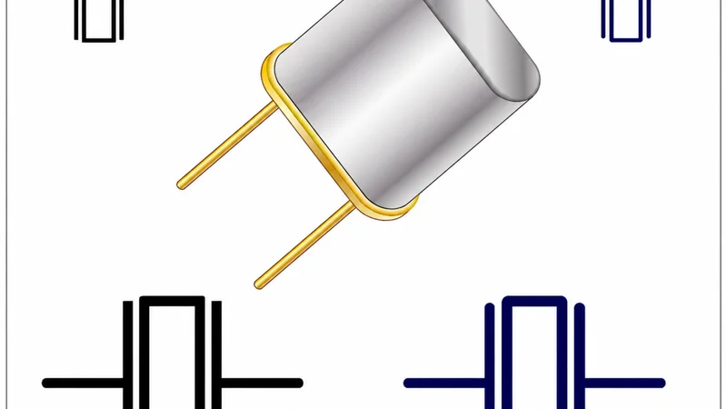
Quartz Crystal Oscillator
:Key Takeaways
● Crystals are passive resonators. A bare quartz crystal is a piezoelectric wafer that needs an external Pierce or Colpitts circuit to oscillate. An ABM8G 16 MHz crystal from Abracon offers ±50 ppm frequency tolerance and ±50 ppm stability with typical shunt capacitance around 5 pF, 18 pF load capacitance and 100 µW drive level. Without proper load capacitors and a series resistor the crystal may be over-driven or fail to start.
● Crystal oscillators integrate the amplifying circuit. Packaged XOs combine the crystal, Pierce inverter and load capacitors in one SMD enclosure. For example, the ECS-3225MV multi-volt oscillator covers 6–50 MHz and consumes about 3–5 mA at 3.3 V with ±25 ppm stability and 1 picosecond (ps) root-mean-square (RMS) phase jitter.
● TCXO and OCXO deliver orders of magnitude better stability. Abracon's ASTXR TCXO achieves ±0.5 ppm stability over –30 °C to +85 °C while drawing around 1.5 mA. Kyocera-AVX's KLN OCXO offers ±5–±100 ppb stability with ±100 ppb initial tolerance, 5 minutes warm-up and about 1.5 W steady-state power consumption.
● VCXO allows pull-range tuning. Microchip's PL500-37 VCXO supports 36–130 MHz crystals, ±150 ppm pull range, 2.5/3.3 V supply and 2.5 ps RMS jitter. A control voltage varies the internal varicap capacitance, allowing small frequency adjustments for PLLs or data recovery circuits.
● Micro-electro-mechanical system (MEMS) oscillators are robust and programmable. SiTime's SiT8008 MEMS oscillator covers 1–110 MHz with ±20 ppm stability and draws 3.6 mA at 3.3 V. MEMS devices withstand shock and vibration better than quartz and offer factory-programmable frequencies, though phase noise at far offsets is typically higher than high-quality quartz oscillators.
● Choosing a timing source is a system trade-off. Crystals are inexpensive and low power but require careful Pierce circuit design. XOs simplify design and offer better jitter performance. TCXO and OCXO add cost and power for parts-per-billion stability. VCXO enable PLL tuning. MEMS oscillators simplify supply chains and handle vibration.
Introduction
Quartz has a remarkable property. Applying an electric field across a properly cut quartz plate induces mechanical vibrations at a precise resonant frequency, and conversely mechanical stress produces an electric field. This piezoelectric effect enables quartz resonators to act as extremely high-quality filters. The quartz crystal used in timing applications is a small bar or tuning fork cut from a single crystal of α-quartz. When placed into an electronic oscillator circuit and driven within its linear region, it produces a stable frequency reference. The equivalent electrical model comprises a motional inductance Lm, motional capacitance Cm, motional resistance Rm and a shunt capacitance C0 due to the electrode plates. This high-Q resonator exhibits a series and parallel resonance that allow it to stabilise an amplifier into oscillation at a precise resonant frequency.
Understanding the difference between a bare quartz resonator and a crystal oscillator matters because the choice affects the bill of materials, printed-circuit-board area, jitter budget, startup time and long-term reliability. A discrete crystal with an external amplifier and capacitors is inexpensive and draws no direct power, but it requires careful design of the Pierce oscillator circuit and can be damaged by excessive drive power. Packaged oscillators integrate the resonator, amplifier and load capacitors, eliminating design uncertainty, and specialized variants such as temperature-compensated (TCXO), oven-controlled (OCXO) and voltage-controlled (VCXO) oscillators improve stability or allow frequency tuning at the cost of higher power and price. Modern MEMS oscillators use micromachined resonators with on-chip temperature compensation and digital trimming to deliver accurate clocks in small packages.
What Is a Quartz Crystal?
A quartz crystal is a thin plate cut from a single crystal of silicon dioxide. When voltage is applied across its electrodes the plate flexes; at resonance the stored mechanical energy oscillates with very low loss. In electrical terms the crystal's equivalent circuit consists of a series branch Rm, Lm and Cm representing the mechanical resonator, in parallel with C0 representing the static capacitance of the electrodes. At the series resonance frequency the crystal exhibits a low impedance; slightly above this frequency the impedance becomes inductive and the device resonates in parallel with C0. Because of the high Q (10,000 to 2,000,000), the frequency stability and phase noise of a quartz resonator are superb compared with LC or RC resonators.
Recommended reading: Crystal Oscillator: Fundamentals, Models, and Design Guidelines
The cut of the crystal determines its temperature coefficient and stress sensitivity. AT-cut plates have a parabolic temperature coefficient; at room temperature they exhibit excellent stability and are widely used for frequencies from 1 MHz to 30 MHz. SC-cut crystals (stress compensated) are rotated differently to minimize stress sensitivity and have a third-order temperature curve. They offer much better frequency stability (±0.5 to 10 ppb for OCXO applications) and lower aging at the cost of complexity and price. Tuning-fork crystals, such as 32.768 kHz resonators used in real-time clocks, are cut in a different orientation to lower motional resistance and achieve low power operation. Their frequency (2^15 equals 32,768 Hz) allows simple binary division to 1 Hz, and the resonators consume micro-ampere drive currents.
Crystals may oscillate on their fundamental or overtone modes. The fundamental frequency is limited by thickness; above about 30 MHz the thickness becomes impractically small, so higher frequencies use third or fifth overtones. An AT-cut fundamental crystal such as the Abracon ABM8G (2.5 × 2.0 mm package) is available from 12 MHz to 50 MHz with ±50 ppm tolerance and ±50 ppm stability. The motional parameters of this device include C0 around 5 pF, an equivalent series resistance of 80 Ω at 16 MHz and a maximum drive level of 100 µW. Selecting a crystal requires matching the load capacitance CL, drive level and ESR to the oscillator circuit.
What Is a Crystal Oscillator?
A crystal oscillator (XO) is a self-contained module that incorporates the quartz resonator, the transistor amplifier (often a CMOS inverter or transconductance amplifier), load capacitors and a feedback resistor in a hermetic package. The oscillator circuit is typically a Pierce or Colpitts configuration designed to provide 360 degrees phase shift and unity loop gain at the crystal's parallel resonance. Since all components are factory-matched, an XO offers guaranteed startup, calibrated frequency and known phase noise performance. The output stage can buffer the oscillator and provide various logic levels (CMOS, LVDS, LVPECL). Typical rise and fall times are a few nanoseconds, ensuring good signal integrity.
To illustrate, the ECS-3225MV is a "multi-volt" oscillator that operates from 1.62 V to 3.63 V and covers 6 MHz to 50 MHz. The frequency stability options include ±25 ppm or ±50 ppm over –40 °C to +85 °C, and the oscillator produces a CMOS output with a 45–55% duty cycle. Phase jitter integrated over 12 kHz to 20 MHz is 1 ps RMS, and the typical supply current is 3–5 mA depending on frequency. Another example is the FA-238 oscillator from Epson; it offers fundamental frequencies from 16 MHz to 120 MHz with ±15 ppm initial tolerance, ±30 ppm stability over –20 °C to +70 °C, load capacitance options of 9–16 pF and motional resistances as low as 20 Ω. Compared with a bare crystal these modules require only power and ground; no external capacitors or bias resistors are needed.
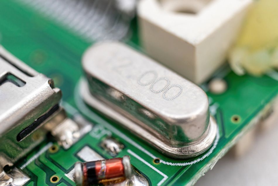
The Pierce Oscillator Circuit
Many microcontrollers and ASICs contain an on-chip inverting amplifier connected to external pins for a crystal. The Pierce oscillator uses this inverter with a feedback network comprising the crystal and two capacitors C1 and C2 to ground. The loop gain must be greater than one at startup and settle to unity at steady state. A resistor Rf across the amplifier provides bias and defines the operating point. Some designs add a series resistor Rs on the crystal's output side to limit drive level and ensure that the amplifier meets its negative resistance specification.
Recommended reading: Crystal Oscillator Circuit Design: Pierce Oscillator Guide for Precision Frequency Generation
The load capacitance seen by the crystal is given by:
CL = (C1 × C2) / (C1 + C2) + Cs
where Cs accounts for stray capacitance of traces, pins and the package, typically 2–5 pF. To achieve a specified CL the external capacitors must be carefully calculated. STMicroelectronics recommends solving C1 = C2 = 2 × (CL – Cs) for symmetrical loads. For example, if CL = 15 pF and Cs = 5 pF, each capacitor should be around 20 pF. Another worked example: for CL = 18 pF and Cs = 5 pF, each capacitor must be about 26 pF. Using high-Q NP0/C0G dielectric capacitors minimizes losses and drift. Designers should also minimize trace length and place the capacitors close to the crystal to reduce stray capacitance.
The series resistor Rs helps limit the drive level. Over-driving a crystal can cause nonlinearities, increased aging or even fracture due to excessive mechanical stress. NXP notes that placing a resistor of 100 Ω to 330 kΩ in series with the crystal prevents over-drive and that it should be on the output side of the inverter so that the crystal sees a low source impedance for startup. The resistor also reduces negative resistance to increase start-up margin and shape the oscillation amplitude.
Several microcontroller application notes provide formulas for critical transconductance and startup time. ST's AN2867 derives a condition for the amplifier transconductance gm to exceed a critical value: gm > 4π·f·Rs / (Q × C0 × CL). Ensuring margin above this threshold guarantees startup. Exceeding the crystal's specified drive level (for example, 100 µW for ABM8G) can lead to frequency pulling and long-term damage, so designers should measure oscillator amplitude and adjust Rs accordingly.
Crystal Selection
Selecting a quartz crystal involves balancing several parameters:
● Nominal frequency and mode: Ensure the resonant frequency matches the required clock and that the device operates on its fundamental mode. For frequencies above roughly 30 MHz, overtone crystals (third or fifth) or packaged oscillators are more practical. The Abracon ABM8G series offers fundamental frequencies from 12 MHz to 50 MHz, whereas the NDK NX3225GA automotive crystal covers 9.8–50 MHz.
● Frequency tolerance at 25 °C: This indicates how far the initial frequency may deviate from nominal. Typical options are ±10 ppm to ±50 ppm. The ABM8G is available with ±50 ppm tolerance, while the Epson FA-238 offers tighter ±15 ppm options. Tighter tolerance increases cost.
● Frequency stability over temperature: Also known as total stability, this includes drift due to temperature, load and supply variations. Standard crystals have ±50 ppm stability over –40 °C to +85 °C; the NX3225GA has ±150 ppm over –40 °C to +150 °C to meet automotive AEC-Q200.
● Load capacitance CL: Manufacturers specify the load capacitance at which the crystal is calibrated (commonly 8–20 pF). The NX3225GA offers 6–32 pF options. A mismatch between the designed CL and the actual load will pull the frequency off target.
● Equivalent series resistance (ESR): ESR limits the oscillation margin; lower ESR is better. For example, ABM8G has ESR values of 80 Ω at 16 MHz, while the NX3225GA has 120 Ω typical at 12–20 MHz. Microcontrollers specify a maximum ESR they can drive.
● Drive level: Exceeding the maximum drive (expressed in microwatts) increases aging and may crack the crystal. ABM8G's maximum drive is 100 µW, FA-238 requires 10–100 µW, and NX3225GA is rated for 10 µW with a 200 µW maximum. Series resistors and selecting appropriate transconductance help control drive.
● Aging: Frequency drift over time due to contamination or stress. The ABM8G ages ±3 ppm per year, FA-238 ±5×10⁻⁶/year and NX3225GA ±1 ppm/year. Applications requiring long-term accuracy should consider oscillators with compensation or periodic calibration.
When selecting a crystal, examine the microcontroller or PLL datasheet for maximum ESR, minimum negative resistance and required transconductance. Choose a crystal with CL and ESR that meet these limits, and calculate external capacitors accordingly. Consider environmental factors: automotive or industrial designs may need extended temperature ranges and shock-resistant packages. If the application cannot tolerate ±50 ppm drift, a TCXO or MEMS oscillator may be more appropriate.
Oscillator Types: XO, TCXO, OCXO, VCXO and MEMS
A wide range of oscillator modules exists, differing in stability, power and complexity. The table below summarizes typical characteristics; values are representative examples and not absolute limits.
Type | Example parts | Stability | Phase jitter / noise | Supply current | Pros | Cons |
XO (simple) | ECS-3225MV 20 MHz; Epson FA-238 16 MHz | ±25 or ±50 ppm | ~1 ps RMS (12 kHz–20 MHz) | 3–5 mA at 1.8–3.3 V | Small, low power, no external circuitry | Moderate stability; limited frequencies |
TCXO | Abracon ASTXR 19.2 MHz | ±0.5 ppm over –30 °C to +85 °C | ~–115 dBc/Hz at 100 Hz offset | ~1.5 mA at 2.7–3.0 V | High stability in small package; low power | More expensive; limited pull range |
OCXO | Kyocera-AVX KLN 10 MHz | ±5 ppb to ±100 ppb | ~–100 dBc/Hz at 10 Hz; floor –140 dBc/Hz | 1.5 W steady-state | Ultra-stable; low aging (±100 ppb/year) | Bulky; high power; ~5 min warm-up |
VCXO | Microchip PL500-37 77.76 MHz | ±150 ppm pull range | ~2.5 ps RMS period jitter | 5–8 mA at 2.5/3.3 V | Frequency tuning via control voltage | Requires clean control voltage |
MEMS | SiTime SiT8008 25 MHz | ±20 or ±50 ppm | 0.5–2 ps (12 kHz–20 MHz) | ~3.6 mA at 3.3 V | Programmable, shock resistant, fast startup | Higher phase noise at far offsets |
TCXO modules use an analogue temperature sensor and compensation network to correct the frequency drift of the quartz resonator. In Abracon's ASTXR series the compensation achieves ±0.5 ppm stability over –30 °C to +85 °C while consuming only 1.5 mA. Additional voltage- or load-sensitivity metrics show ±0.1 ppm sensitivity to ±5% supply variation and ±0.2 ppm sensitivity to ±10% load change. Long-term stability is ±0.7 ppm per year, making TCXOs suitable for GNSS receivers, wireless modules and precision timekeeping.
OCXO modules enclose the resonator in a temperature-controlled oven maintained near its turnover temperature. Kyocera-AVX's KLN OCXO has options from ±5 ppb to ±100 ppb over –40 °C to +85 °C. The device requires 5 V or 12 V supply and draws roughly 1.5 W at steady-state. The warm-up time to reach initial tolerance is roughly five minutes. Aging is ±1 ppb per day or ±100 ppb per year for a 10 MHz unit. Such OCXOs are used in base stations, precision instrumentation, test equipment and frequency references where sub-ppm accuracy is essential. Low-phase-noise variants like Crystek's CCHD-957 achieve –100 dBc/Hz at 10 Hz offset and –169 dBc/Hz noise floor.
VCXO modules incorporate varactor diodes in the oscillator circuit so that the output frequency is linearly proportional to a control voltage. Microchip's PL500-37 low-phase-noise VCXO provides a pull range of ±150 ppm, about 2.5 ps RMS jitter and operates on 2.5 V or 3.3 V. VCXOs are often used in phase-locked loops to fine-tune the reference frequency. However, pulling the frequency away from the crystal's nominal frequency degrades Q and increases jitter.
MEMS oscillators use silicon resonators driven electrostatically or thermally and integrate temperature sensing and compensation circuitry. SiTime's SiT8008 covers 1 MHz to 110 MHz with ±20 ppm frequency stability and ±10 ppm initial tolerance. The oscillator draws 3.6 mA at 3.3 V and has standby current below 1 µA. Phase jitter over 12 kHz to 20 MHz is about 0.5–2 ps. MEMS devices withstand g-level shocks and vibration better than quartz and offer quick factory programming for any frequency, making them ideal for low-volume or field-programmable designs. Their phase noise at far offsets (for example above 1 MHz) is typically higher than high-quality AT- or SC-cut crystals.
Crystal vs Oscillator: Decision Matrix
Choosing between a bare quartz crystal and a packaged oscillator involves weighing cost, performance, and design effort. The table below summarizes major trade-offs.
Attribute | Quartz crystal + Pierce circuit | Packaged XO | TCXO | OCXO | VCXO | MEMS oscillator |
BOM cost (USD) | Low (0.10–0.50) | Moderate (0.50–2) | ~3–6 | ~20–100 | ~2–5 | ~1–3 |
Board area | Crystal + caps + R; ~20–30 mm² | Single SMD (2×1.6 to 5×7 mm) | Small (2.5×2.0 mm) | Large (25×25 mm) | 5×7 mm or 8-pin | 2×1.6 to 5×7 mm |
Design effort | Calculate C1, C2, Rs; ensure gm margin | Plug-and-play | Minimal; supply filtering | Moderate; needs warm-up | Requires stable control voltage | Minimal; supply decoupling + programming |
Frequency flexibility | Fixed; discrete values | Fixed per part; many standard frequencies | Fixed; standard frequencies | Fixed; 10 MHz typical | Tunable ±50–200 ppm | Factory programmable |
Temperature stability | ±50–150 ppm | ±25–50 ppm | ±0.1–1 ppm | ±0.005–0.1 ppm | ±20–50 ppm | ±20–50 ppm |
Phase noise / jitter | 5–20 ps typical | 1–2 ps RMS | 0.3–1 ps | 100 fs–1 ps | ~2–3 ps RMS | 0.5–2 ps |
Power consumption | Negligible | 3–5 mA | 1–2 mA | 1.5 W | 5–8 mA | 3–4 mA |
Startup time | Several hundred µs to ms | <10 ms | 0.5 ms amplitude; 2 ms frequency | ~5 minutes | <1 ms | <5 ms |
Shock and vibration | Fragile | Better than bare crystals | Similar to XO | Sensitive to vibration | Similar to XO | Highly robust |
Using a bare crystal with a microcontroller saves cost and draws almost no quiescent current. However, ensuring reliable startup requires matching the load capacitance and verifying the microcontroller's negative resistance. Designers must be careful not to over-drive the crystal; ageing is higher than in packaged oscillators because environmental factors can contaminate the resonator. Board layout must keep traces short, guard the ground plane and isolate the resonator from strong digital signals. The layout should include a ground guard ring around the crystal and its capacitors on single-layer boards to minimize coupling.
Packaged XOs simplify the design; they have factory-trimmed load capacitors and guarantee startup. Their cost is modest, and jitter performance is typically better because the internal amplifier is optimized for the crystal. However, they are limited to fixed frequencies and may not meet stringent temperature requirements without resorting to TCXO or OCXO types.
TCXOs are ideal when ±10 ppm or better frequency stability is required over wide temperature ranges but power consumption must remain low. They are widely used in radio modules, GNSS receivers and network time references. OCXOs provide the highest stability and lowest phase noise but consume significant power and occupy large board area; they are reserved for professional equipment such as telecom base stations, instrumentation and timing infrastructure.
MEMS Oscillators vs Quartz
MEMS technology uses silicon micro-structures machined using processes similar to integrated circuits. The resonator can be a flexural beam or a bulk-acoustic wave device. Unlike quartz, which requires metal plating and hermetic packaging, MEMS resonators are encapsulated within the silicon die and vacuum-sealed, providing excellent resistance to shock and vibration. The resonator frequency can be trimmed digitally by programmable capacitors, enabling any frequency within the device's range. For example, the SiTime SiT8008 can be factory-programmed from 1 MHz to 110 MHz and offers ±20 ppm frequency stability, 3.6 mA current at 3.3 V and RMS phase jitter down to 0.5 ps.
MEMS oscillators integrate temperature sensing and compensation to maintain stability over –40 °C to +85 °C. They also include digital control of startup and shut-down, allowing fast enable or disable times and micro-ampere standby currents. Compared with quartz, MEMS devices offer:
● Shock and vibration tolerance: The silicon resonator has much lower mass and higher mechanical strength, so the frequency shift under acceleration is orders of magnitude smaller. This makes MEMS suitable for automotive and industrial environments.
● Programmability: One part number can be programmed to many output frequencies; this simplifies inventory and allows quick turnaround for prototypes.
● Low startup time: MEMS devices start within microseconds to a few milliseconds, whereas quartz crystals may require tens of milliseconds and OCXOs minutes.
However, MEMS oscillators also have limitations. Their noise floor at large frequency offsets is often higher than high-quality quartz resonators, because the Q of MEMS resonators is lower than that of large AT-cut crystals. In high-performance RF synthesizers or instrumentation requiring phase noise below –150 dBc/Hz, quartz OCXOs or SC-cut crystals remain superior. MEMS oscillators also exhibit supply and load sensitivity; careful decoupling and output impedance matching are essential.
PLL Integration
Many systems derive multiple high-frequency clocks from a low-frequency reference using a phase-locked loop or fractional-N synthesizer. In such cases the choice of reference oscillator directly influences output jitter. For example, a microcontroller may use a 32.768 kHz crystal to generate its internal 48 MHz USB clock via a PLL. The 32.768 kHz tuning-fork crystal consumes only micro-watts of drive current and has high stability; the frequency is exactly 2^15 and divides to 1 Hz easily, making it ideal for real-time clocks. When used as the reference for a PLL, the noise of the 32 kHz crystal is multiplied by the PLL's multiplication factor N; thus phase noise increases by 20·log10(N), and jitter is amplified accordingly. High-frequency PLLs used for 480 MHz USB, 25 MHz Ethernet or 125 MHz Gigabit clocks often use 25 MHz or 16 MHz crystals as references because they provide a good compromise between low cost and adequate jitter.
The IEEE and ITU-T standards specify integration bandwidths for jitter measurement. Raltron's technical note explains that RMS jitter is derived by integrating the phase noise L(f) across a specified band; for SONET/SDH equipment the standard band is 12 kHz to 20 MHz. Integrating the phase noise curve for a 312.5 MHz oscillator from 12 kHz to 20 MHz yielded a noise power of –63 dBc and an RMS jitter of 0.72 ps. Similarly, many oscillator datasheets quote jitter over this band to allow comparison. For example, the ECS-3225MV oscillator lists 1 ps RMS jitter over 12 kHz to 20 MHz. When selecting an oscillator for a PLL, ensure its jitter specification meets the requirements of the downstream SerDes or communication standard. Some SerDes require reference clock jitter below 100 fs RMS (12 kHz–20 MHz) to achieve 112 Gbit/s PAM4 error performance.
Common Mistakes in Crystal Oscillator Design
Designers frequently encounter issues with discrete crystal oscillator circuits. The following mistakes are common:
● Over-driving the crystal: Exceeding the specified drive level causes non-linear operation and accelerated aging. Always calculate the amplifier's transconductance and include a series resistor to limit power.
● Incorrect load capacitance: Selecting capacitors without considering stray capacitance leads to frequency error. Use the formula CL = (C1 × C2)/(C1 + C2) + Cs and choose NP0 or C0G capacitors.
● Poor PCB layout: Long traces and ground loops introduce parasitic inductance and capacitance that can prevent oscillation. Place the crystal and capacitors close to the microcontroller pins, keep the loop area small, and avoid crossing high-speed traces over the oscillator network. A guard ring around the oscillator components connected to ground reduces leakage and noise.
● No ground guard or shielding: Without a ground guard or shield, digital noise couples into the crystal leads causing phase noise and drift. Provide a local ground plane under the crystal and add guard traces when using single-layer boards.
● Omitting ESD protection on enable pins: Many oscillators include an enable or disable pin. Failing to protect this pin can allow ESD events to damage the oscillator. Use series resistors and clamping diodes if necessary.
● Wrong cut or overtone: Using an AT-cut crystal above its fundamental limit can result in unstable oscillation. Choose an overtone crystal or a packaged XO for frequencies above about 30 MHz.
● Assuming identical performance across suppliers: Different manufacturers use different plating thicknesses, cuts and packaging. Compare datasheets for tolerance, stability, ESR, drive level and aging.
It is important to note that since several of these mistakes trace back to board layout rather than the crystal itself.
Recommended reading: PCB Layout: A Comprehensive Guide
Application Contexts
Timing requirements vary dramatically across applications. The following examples illustrate appropriate choices:
1. Microcontroller clock: A 16 MHz or 8 MHz AT-cut crystal with ±50 ppm tolerance suffices for general microcontrollers. For low-power wearables, a 32.768 kHz tuning-fork crystal drives an RTC; its 2^15 frequency simplifies division to 1 Hz.
2. USB 480 MHz and Ethernet 25/125 MHz references. High-speed serial interfaces require low jitter. A 25 MHz XO or TCXO with ±50 ppm stability and 1 ps RMS jitter such as the ECS-3225MV is appropriate. For Gigabit Ethernet, ±100 ppm drift is allowed by the IEEE 802.3 specification.
3. RF synthesizer reference. Fractional-N synthesizers use a low-phase-noise crystal or OCXO as reference. For a 1 GHz local oscillator with 10 Hz resolution and sub-100 fs jitter, an SC-cut crystal or low-noise OCXO like Crystek CCHD-957 is recommended; its phase noise is –100 dBc/Hz at 10 Hz offset and the noise floor is –169 dBc/Hz.
4. Automotive electronics. Engine control units and infotainment systems often use 24 MHz or 40 MHz crystals certified to AEC-Q200. The NDK NX3225GA offers ±150 ppm stability over –40 °C to +150 °C and 8 pF load capacitance, with ESR less than 120 Ω and drive level 10 µW.
5. Real-time clocks and wearables. 32.768 kHz tuning-fork crystals consume micro-watts and deliver ±20 ppm stability at room temperature. The integrated RTC module inside the DS3231 uses an internal TCXO to achieve ±2 ppm accuracy across –40 °C to +85 °C. SiTime's SiT153x MEMS series offers ±10 ppm stability with 1 µA supply current.
6. High-reliability aerospace. Radiation-hard OCXOs and SC-cut crystals with ±5 ppb stability are used for inertial navigation and satellite timing. Kyocera-AVX's KLN series is available with acceleration sensitivity less than 0.3 ppb per g and options for 5 V or 12 V supply.
Conclusion
The choice between a quartz crystal, a crystal oscillator, a TCXO, an OCXO, a VCXO or a MEMS oscillator depends on the application's tolerance for frequency error, jitter, temperature variation, board area and cost. Bare crystals plus a Pierce oscillator provide the lowest cost and power but require careful design of capacitors, resistors and PCB layout to meet the specified load capacitance and drive level. Packaged XOs eliminate this complexity and offer robust startup and better jitter performance. TCXO modules add temperature compensation to achieve parts-per-million stability with minimal power. OCXO modules deliver parts-per-billion stability and ultra-low phase noise at the cost of large size and high power. VCXO modules enable PLL tuning by varying the frequency with a control voltage. MEMS oscillators are programmable, shock-resistant and increasingly competitive with quartz for general-purpose clocks.
As semiconductor processes improve and temperature-compensation techniques advance, MEMS oscillators are likely to capture a larger share of timing markets. Integrated timing solutions that combine a low-phase-noise TCXO with a PLL and fractional divider are appearing in modern system-on-chips, reducing the need for external crystals. Nevertheless, quartz remains the gold standard for very low phase noise and long-term stability. Engineers selecting timing components should evaluate the complete system—accuracy, jitter, supply constraints, operating environment and design complexity—to choose the optimal solution.
FAQ
What is the difference between a quartz crystal and a crystal oscillator?
A quartz crystal is a passive resonator consisting of a piezoelectric plate with electrodes. It requires an external circuit to oscillate and its frequency depends on the cut and load capacitance. A crystal oscillator is an active module containing the quartz crystal, an amplifier and load capacitors in a sealed package. It only needs power and ground to generate a clock. Crystals are cheaper but demand careful design, whereas crystal oscillators simplify development and offer guaranteed stability and startup.
Do I need load capacitors with a crystal oscillator (XO)?
No. Packaged crystal oscillators include the necessary load capacitors and provide a calibrated output. External load capacitors are only required when using a bare quartz crystal in a Pierce oscillator circuit. In that case, calculate the capacitors using CL = (C1 × C2)/(C1 + C2) + Cs and match them to the crystal's specified load capacitance.
When should I use a TCXO instead of a crystal?
Use a TCXO when the system cannot tolerate the ±50 ppm frequency drift typical of standard crystals over temperature. Wireless modules, GNSS receivers and network equipment often require ±1 ppm or better stability. TCXOs like Abracon's ASTXR provide ±0.5 ppm stability over –30 °C to +85 °C while consuming only around 1.5 mA.
What is the difference between a quartz crystal and a MEMS oscillator?
Quartz crystals rely on the piezoelectric effect of single-crystal quartz and offer very high Q, low phase noise and good long-term stability. MEMS oscillators use silicon micromachined resonators integrated with temperature compensation and digital trimming. They are programmable, shock-tolerant and have fast startup. MEMS oscillators like SiT8008 provide ±20 ppm stability and 0.5–2 ps jitter, but their phase noise floor is generally higher than that of premium quartz oscillators.
Why is 32.768 kHz used for real-time clocks?
The frequency 32.768 kHz equals 2^15, enabling simple binary division by power-of-two flip-flops to produce a one-hertz time base. The tuning-fork crystal used at this frequency operates at very low power and has high stability, making it ideal for battery-powered watches and microcontroller real-time clocks.
What is drive level and why does it matter?
Drive level is the power dissipated in the crystal during oscillation, usually specified in microwatts. Exceeding the maximum drive level generates nonlinear stress, increases aging and may crack the quartz. The Abracon ABM8G crystal has a maximum drive of 100 µW, and the NDK NX3225GA is specified for 10 µW with a 200 µW maximum. Designers should adjust the series resistor and amplifier transconductance to keep the drive within specification.
How do I calculate load capacitance for a crystal?
Use CL = (C1 × C2)/(C1 + C2) + Cs, where Cs is stray capacitance. For symmetric designs C1 = C2 = 2 × (CL – Cs). For example, a crystal with CL = 18 pF and Cs = 5 pF requires about 26 pF capacitors.
What is the difference between fundamental and overtone crystals?
Fundamental crystals oscillate at the frequency determined by their thickness; overtone crystals use the third or fifth harmonic to achieve higher frequencies without making the plate too thin. Fundamental AT-cut crystals are practical up to about 30 MHz; above this frequency overtone crystals or packaged oscillators are used.
References
- A. S. Sedra, K. C. Smith, T. C. Carusone, and V. Gaudet, Microelectronic Circuits, 8th ed. New York, NY, USA: Oxford University Press, 2021.
- P. Horowitz and W. Hill, The Art of Electronics, 3rd ed. Cambridge, U.K.: Cambridge University Press, 2015.
- Wevolver, Abiola Ayodele, Crystal Oscillator: Fundamentals, Models, and Design Guidelines. [Online]. Available: https://www.wevolver.com/article/crystal-oscillator-fundamentals-models-and-design-guidelines
- John R. Vig - tutorial on Quartz Crystals and Oscillators.pdf. [Online]. Available: http://www.resonal.com/Downloads/John%20R.%20Vig%20-%20tutorial%20on%20Quartz%20Crystals%20and%20Oscillators.pdf
in this article
1. :Key Takeaways2. Introduction3. What Is a Quartz Crystal?4. What Is a Crystal Oscillator?5. Crystal Selection6. Oscillator Types: XO, TCXO, OCXO, VCXO and MEMS7. Crystal vs Oscillator: Decision Matrix8. MEMS Oscillators vs Quartz9. PLL Integration10. Common Mistakes in Crystal Oscillator Design11. Application Contexts12. Conclusion13. FAQ14. References