CNC vs 3D Printing: How to Choose the Right Process
A practical comparison of CNC machining and 3D printing for engineers, covering tolerances, surface finish, materials, geometry, and cost.

13 Oct, 2026. 11 minutes read
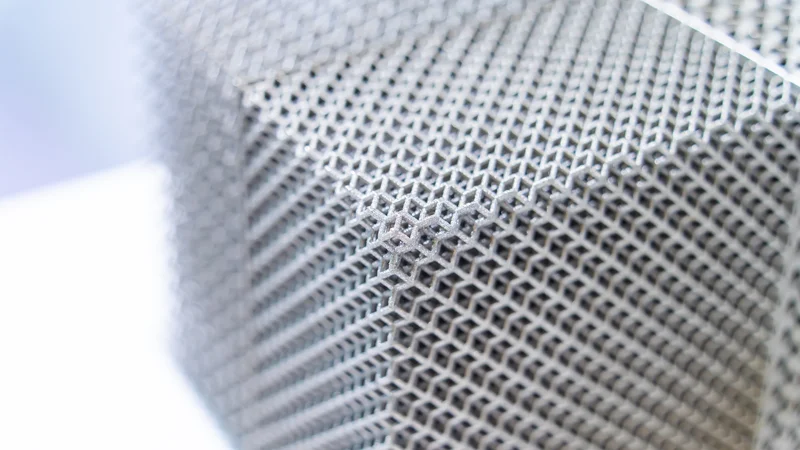
3D printing can produce un-machinable geometries like lattices
Key Takeaways
CNC machining can achieve tighter tolerances, though some 3D printing processes offer good accuracy.
Surface finish is the biggest differentiator. A standard as-machined CNC surface is Ra 3.2 µm, but 3D printing rarely hits that finish without extensive post-processing.
3D printing’s main advantage is geometry. Internal cavities and lattice structures are difficult or impossible to achieve by traditional methods, and parts with internal geometries cannot be machined at all.
CNC machining is generally more cost-effective in higher volumes, but the actual break-even point depends on several factors.
The two are complements more often than rivals. Metal printed parts can benefit from machining as a post-processing technique.
Introduction
Choosing between CNC vs 3D printing is one of the first design-for-manufacturing decisions you make, and getting it wrong can be expensive. Print a part with strict surface finish requirements and you may end up having to machine it anyway. Machine a part with internal channels and you will find no tool can reach them.
The two manufacturing methods sit at opposite ends of the spectrum. CNC machining is subtractive manufacturing: you start with a solid block and remove everything that is not the part. 3D printing is additive manufacturing, defined by ISO/ASTM 52900 as building “physical three-dimensional (3D) geometries by successive addition of material.”[1]
This guide compares them on key criteria: dimensional accuracy, surface finish, materials, geometric freedom, cost against volume, lead time, and material waste.
How Each Process Works
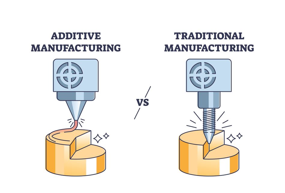
Both processes start from the same place: a 3D model. What happens to that digital file is where they diverge.
CNC Machining: Subtractive Manufacturing
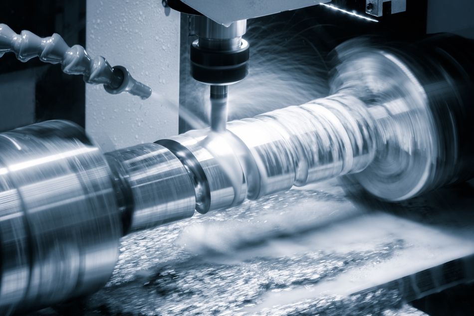
In CNC machining, CAM software converts the 3D model into toolpaths, and computer-controlled cutting tools remove material from a workpiece. Mills, lathes, and routers cover most of the work, with milling the most common for prismatic parts.
Tool access determines what kind of shapes can and cannot be cut. The cutting tool typically approaches the workpiece from above, and features not reachable from this angle, known as “undercuts,” cannot be machined with a tool like a standard end mill.[2]
More cutting angles are unlocked when the machine has more axes of operation. For example, a 5-axis machine tilts the spindle to reach difficult undercuts, but even multi-axis CNC machines cannot cut internal geometries.[2]
3D Printing: Additive Manufacturing
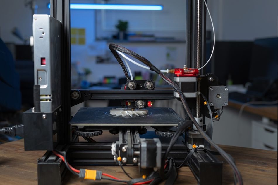
In 3D printing, a slicer converts the 3D model into layers and machine instructions, and the 3D printer builds the part layer by layer. ISO/ASTM 52900:2021 is the current terminology standard sorts commercially available systems into seven process categories.[1]
The ones to be considered most often in a CNC vs 3D printing decision are the more common categories like MEX and PBF.
Process category | ISO/ASTM definition[1] | Familiar examples |
Material extrusion (MEX) | “...material is selectively dispensed through a nozzle or orifice” | FDM, filament printers |
Vat photopolymerization (VPP) | “...liquid photopolymer in a vat is selectively cured by light-activated polymerization” | SLA, resin printers |
Powder bed fusion (PBF) | “...thermal energy selectively fuses regions of a powder bed” | SLS, metal L-PBF, DMLS, Multi Jet Fusion |
Binder jetting (BJT) | “...a liquid bonding agent is selectively deposited to join powder materials” | Sand and metal binder jetting |
Material jetting (MJT) | “...droplets of feedstock material are selectively deposited using inkjet print heads” | PolyJet |
Directed energy deposition (DED) | “...focused thermal energy is used to fuse materials by melting as they are being deposited” | WAAM, laser cladding |
Sheet lamination (SHL) | “...sheets of material are bonded to form a part” | Laminated object manufacturing |
Recommended reading: How Does 3D Printing Work? An Introduction to Additive Manufacturing
Tolerances and Dimensional Accuracy
The dimensional accuracy of manufacturing equipment, in addition to other factors like materials, determines the tightest achievable tolerance that can be specified in a technical drawing. Note that there is variation in 3D printing accuracy and achievable tolerance across different technologies.
Achievable CNC machining tolerances closely match the standard tolerances defined in ISO 2768-1:1989, which contains the table below for linear dimensions.[3] “Fine” tolerances can be achieved with precision machining techniques.
Nominal size | Fine tolerance class | Medium tolerance class |
0.5 to 3 mm | ±0.05 mm | ±0.1 mm |
Over 3 to 6 mm | ±0.05 mm | ±0.1 mm |
Over 6 to 30 mm | ±0.1 mm | ±0.2 mm |
Over 30 to 120 mm | ±0.15 mm | ±0.3 mm |
Over 120 to 400 mm | ±0.2 mm | ±0.5 mm |
Over 400 to 1000 mm | ±0.3 mm | ±0.8 mm |
Achievable 3D printing tolerances are often specified as a percentage of the nominal dimensions, as well as a lower limit in millimeters.[4] This lower limit is typically higher than fine machining tolerances.The table below shows approximate achievable tolerances, specified by 3D printer manufacturer Raise3D, for four major 3D printing technologies.[4]
Process | Tolerance | Lower limit |
FDM | ±0.5% | ±0.5 mm |
SLA | ±0.2% | ±0.1 mm |
PBF (plastic) | ±0.3% | ±0.3 mm |
PBF (metal) | ±0.2% | ±0.1 mm |
The tables indicate that on small parts, a process like SLA or metal PBF can be nominally tighter than default machining. However, precision machining can reach much tighter tolerances—tighter even than the default fine tolerances in the ISO table.
This is because ISO 2768 indicates standards rather than limits. The values are what you receive from a machinist when your drawing specifies nothing, but machining can be specified far tighter. Equipment like Swiss-style turning centers can even reach tolerances as tight as 0.005 mm.
NIST noted in 2012 that standard tolerance levels for the ISO 10791-7 machining test artifact “are on the order of 0.020 mm, likely tighter than even high-end metal-based AM machine capabilities.”[5] Metal printing has improved since, but 3D printing as a whole hits its tolerance ceiling sooner than machining, which benefits from the ability to make multiple passes over the workpiece.
Note also that 3D printing is anisotropic, while machining is not. Z-axis dimensions that traverse multiple layers of the print can be subject to different tolerance limits than X-Y dimensions.
Recommended reading: What Is Swiss Machining? Swiss-Type CNC Lathes Explained
Surface Finish
Machines and printed parts differ more when it comes to surface finish than they do when it comes to tolerances.
A standard as-machined CNC surface is Ra 3.2 µm, while the finest as-machined finish is 0.4 µm.[6] Machinists will adjust the process depending on the exact finish required.
3D printed surface finishes vary by process and material. Common processes like FDM leave layer lines on the print, significantly affecting surface roughness. When a finish is specified on a technical drawing, it is often achieved through a post-processing technique like bead blasting.[7]
The table below shows example 3D printed surface roughness values taken by Xometry.[7] For industrial processes, the post-processed surface is considered a more useful indication than the as-printed surface.
Process | Ra (µm) | Notes |
CNC machining | 3.2 | Standard as-machined |
CNC machining | 0.4 | Finest as-machined |
FDM | 22.5 | ASA filament |
SLA | 1.5 | |
SLS + bead blasting | 4.5 | PA12 |
DMLS + bead blasting | 6 | Stainless 316L |
Note that roughness on a printed part is a function of the surface’s orientation, so the same feature can be smooth or rough depending on how it is oriented in the build.[8]
Materials
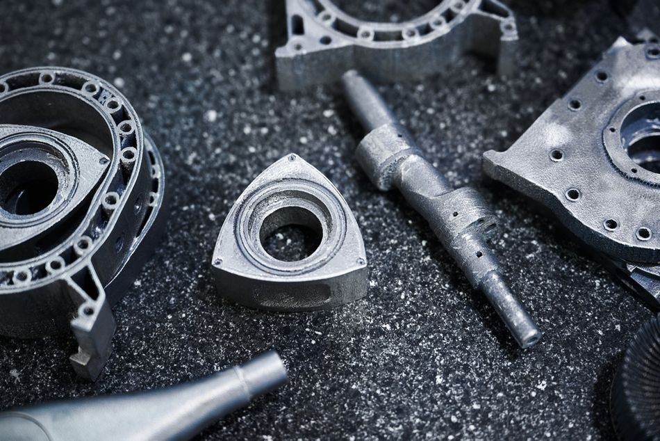
CNC machining works from solid stock, including a very wide range of materials like aluminum, steel, stainless, brass, titanium, engineering thermoplastic stock, and composites. Because the part is cut from wrought or cast material, it inherits that stock’s bulk properties and certification.
3D printing is constrained to feedstock the process can fuse or cure. Material extrusion commonly uses thermoplastic filament such as PLA, PETG, ABS, and nylon. Vat photopolymerization uses photopolymer resins, and powder bed fusion covers polymer powders as well as metals Titanium alloys are also widely printed, and expensive alloys are where the material-saving advantage of 3D printing is most evident, for reasons covered below.
Most CNC machines can process most machinable materials, but the same is not true of 3D printing. A desktop 3D printer running PLA is a prototyping tool, and moving from PLA to an engineering polymer or a metal usually means changing to a more advanced printing process like SLS or DMLS rather than changing spools.
A machined part starts as fully dense, homogeneous stock, so its bulk properties come from the certified material. A printed part is built layer by layer, which is why its quality attributes have to be established on the built part rather than inherited from the feedstock.
Design Freedom and Geometric Constraints
This is the area where 3D printing wins outright, and it is the only reason strong enough to accept looser tolerances and rougher surfaces.
Printing “allows for the fabrication of unique features, such as functionally graded materials, complex lattice structures, and internal cavities, that are difficult or impossible to achieve with traditional manufacturing methods.”[8] Conformal internal channels, topology-optimized structures, and organic shapes all fall in this category.
Design freedom in machining is constrained by cutting tool access rather than complexity.. Complex geometries that a cutter can still approach from outside—i.e. parts that are highly complex but on one face only—are often cheaper to machine than they are to print, while complex shapes that enclose their own voids are printable and nothing else.
Other geometric constraints in machining relate to cavity depth, wall thickness, and corner radii.
Despite its much greater design freedom, 3D printing has some specific constraints too. It also requires a minimum wall thickness, and in most processes overhanging sections must be supported with dedicated support structures to prevent collapse.
Cost, Volume, and Break-Even Point
The cost structures for CNC machining and 3D printing differ in kind. CNC machining carries setup costs: fixturing, CAM programming, and tooling, amortized across the batch, so cost per part falls as quantity rises. Printing has effectively no tooling, so cost per part is close to flat with quantity. In simple terms, this makes CNC machining more affordable in larger volumes and 3D printing more affordable in smaller volumes.
3D printer manufacturer UltiMaker considers the break-even point in terms of the approximate number of units required for a single order:[9]
Under 10 units: 3D printing usually more more cost-effective
10–100 units: Close enough for other factors to come into play
Over 100 units: CNC machining usually more cost-effective
Calculations can also be made based on yearly volumes. A systematic review in Environmental Science and Technology found that additive manufacturing “has lower production costs” when production volumes are below 42–87,000 per year, “depending on the AM process and part geometry.”[10]
The same review explains what makes printing expensive at volume: “energy-intensive and expensive material feedstocks, excessive material waste during production, high machine costs, and slow rates of production.”[10] An exception comes in situations where “the geometric freedom of AM enables performance improvements that reduce environmental impacts and costs during a product’s use phase.”[10] A lighter part in an aircraft is one such example.
Lead Time
Lead time splits along the same line as cost, and for the same reason: the lack of fixturing for 3D printing makes for very fast small batches, but CNC eventually catches up in bigger volumes, since cutting is faster than printing.
For machining, the long pole is usually not the cutting itself, but fixturing strategy, CAM programming, and first-article inspection, all of which are front-loaded and mostly independent of quantity.
For printing, the long pole is build time plus post-processing. Support removal, depowdering and any finishing operations sit between the build finishing and a usable part.
Material Waste and Sustainability
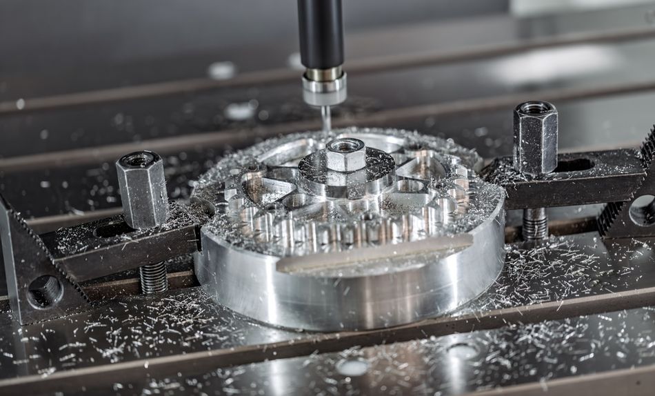
Subtractive manufacturing generates chips by definition, and on expensive alloys that waste adds up.
Additive manufacturing has comparatively little waste. The majority of the feedstock, whether that is metal powder, thermoplastic filament, or something, ends up as the finished part (although some parts will end up being scrapped). Across multiple industries, additive manufacturing “has been used to reduce material use in final parts by 35–80%.”[10]
The caveat is that this does not generalize to every part or every situation. The same review found that “in high-volume mass production, AM can lead to increased energy use and material waste, worsening environmental impacts compared to traditional production methods.”[10] Printing is not automatically the greener option.
Decision Table for Choosing Between CNC Machining and 3D Printing
This table is a set of qualitative drivers that can help you choose between CNC machining and 3D printing.
Decision driver | Choose CNC machining | Choose 3D printing |
Tolerance on functional features | Tighter than the default class, tight in a certified metal, or tight in every axis | Default-class tolerances acceptable, and the tight features sit in one plane |
Surface finish requirement | Sealing, sliding, or bearing faces | Cosmetic or non-contact surfaces |
Geometry | Prismatic, tool-accessible, no internal voids | Internal channels, lattice structures, organic shapes, topology-optimized forms |
Material | Certified wrought stock, full bulk properties needed | Printable feedstock acceptable, anisotropy tolerable |
Quantity | Repeat batches where setup amortizes | One-offs, customization, low-volume production |
Schedule | Time available for fixturing and programming | Need a part without setup work |
Part count in an assembly | Assembly is already simple | Consolidation removes joints, welds, and fasteners |
Using the Processes Together
Framing this as CNC machining vs 3D printing implies that you always pick one. However, in metal manufacturing of high-value parts, you often use both on the same part.
Printed metal parts “are often fabricated first as a near-net shape, a combination of intended nominal geometry and sacrificial support structures, which need to be removed in a subsequent post-processing stage using subtractive manufacturing.”[11]
By combining the two processes, you print the geometry that cannot be machined, then machine the features that cannot be printed to the required tolerance. Sealing faces, bearing bores, and datum surfaces get finished on a mill.
Mass Production Alternatives
Once annual volumes are high enough that tooling amortizes, other competing processes become viable: injection molding for polymers and casting for metals. This represents a different consideration with different break-evens.
If you are weighing printing against molded parts for mass production, our separate comparison of 3D printing versus injection molding covers that trade-off directly.
Recommended reading: 3D Printing vs Injection Molding: Process, Materials, Applications
Conclusion
The CNC vs 3D printing question hinges on which constraints your part is most subjected to.
If the binding constraint is surface finish, repeatability, or certified material properties, machining is usually the better option. If the binding constraint is tolerance, the best resin 3D printing processes can hold their own, but machined dimensions can ultimately be specified far tighter.
If the binding constraint is geometry, 3D printing is often the better choice . Internal channels, lattice structures, and consolidated assemblies are not achievable through machining, no matter how many passes you attempt.
And if the part has both kinds of constraint, which many metal parts do, plan for both processes from the start: print the near-net shape, leave stock on the critical features, and machine them last.
FAQ
Is 3D printing more accurate than CNC machining?
Usually not, but the gap is narrower than it used to be. 3D printing typically requires post-processing to achieve tight tolerances.
Can 3D printing replace CNC machining?
Not generally, and in metal manufacturing the two are usually used together. Printed metal parts are near-net shapes whose supports and tolerance-critical features are finished by machining.[11]
Which is cheaper, CNC machining or 3D printing?
It depends entirely on volume and on what the comparison amortizes. Our sources suggest that 3D printing is cheaper in batches of less than 10 parts or in yearly volumes of less than 42,000 parts.[9][10]
What surface finish can I expect from each process?
A standard as-machined CNC surface is Ra 3.2 µm. To get a comparable texture from 3D printing requires a notably smooth process like SLA or the use of post-processing techniques like bead blasting.
What can 3D printing make that CNC machining cannot?
Anything a cutting tool cannot reach. Internal cavities and channels and complex lattice structures are the standard examples.
Does 3D printing reduce material waste?
Often, but not always. Additive has been used to reduce material use in final parts by 35 to 80% across multiple industries, yet in high-volume mass production it can increase energy use and material waste relative to traditional methods.[10]
References
[1] International Organization for Standardization. ISO/ASTM 52900:2021, Additive manufacturing. General principles. Fundamentals and vocabulary. Geneva: ISO; 2021.
[2] Protolabs Network. How to design parts for CNC machining [Internet]. Amsterdam: Protolabs Network; [cited 2026 Oct 13].
[3] International Organization for Standardization. ISO 2768-1:1989, General tolerances. Part 1: Tolerances for linear and angular dimensions without individual tolerance indications. Geneva: ISO; 1989.
[4] Raise3D. 3D printing tolerances [Internet]. Raise3D; [cited 2026 Oct 13].
[5] Moylan S, Cooke A, Jurrens K, Slotwinski J, Donmez MA. A review of test artifacts for additive manufacturing. Gaithersburg (MD): National Institute of Standards and Technology; 2012. NIST IR 7858.
[6] Protolabs Network. What are the types of surface finishes for CNC machining? [Internet]. Amsterdam: Protolabs Network; [cited 2026 Sep 30].
[7] Xometry Pro. 3D printing surface roughness [Internet]. North Bethesda (MD): Xometry; [cited 2026 Oct 13].
[8] Yang Z, Hong GS, Lu Y, Hu CC, Yang HC, Lane B. Surface roughness repeatability analysis for multi-build overhang parts in powder bed fusion additive manufacturing. InInternational Design Engineering Technical Conferences and Computers and Information in Engineering Conference 2024 Aug 25 (Vol. 88346, p. V02AT02A039). American Society of Mechanical Engineers.
[9] UltiMaker. 3D printing vs. CNC: Comparing additive and subtractive manufacturing [Internet]. Utrecht: UltiMaker; 2025 Apr 9 [cited 2026 Oct 13].
[10] Jung S, Kara LB, Nie Z, Simpson TW, Whitefoot KS. Is additive manufacturing an environmentally and economically preferred alternative for mass production?. Environmental science & technology. 2023 Apr 17;57(16):6373.
[11] Mirzendehdel AM, Behandish M, Nelaturi S. Optimizing build orientation for support removal using multi-axis machining. Computers & Graphics. 2021 Oct 1;99:247-58.
in this article
1. Introduction2. How Each Process Works3. Tolerances and Dimensional Accuracy4. Surface Finish5. Materials6. Design Freedom and Geometric Constraints7. Cost, Volume, and Break-Even Point8. Lead Time9. Material Waste and Sustainability10. Decision Table for Choosing Between CNC Machining and 3D Printing11. Conclusion12. FAQ13. References