Battery Thermal Management for EV Battery Packs
Engineering principles, BTMS architectures, and design tradeoffs.

29 Jun, 2026. 13 minutes read
Key takeaways
A battery thermal management system, or BTMS, keeps lithium-ion batteries in a controlled operating temperature range, commonly around 15-35 °C for best performance
Heat generation in battery cells is not only I²R loss. Ohmic heat, electrochemical polarization, entropic heat, and hysteresis effects vary with state of charge, C-rate, aging state, and temperature.
Liquid cooling with cold plates and water-glycol coolant is the dominant approach for many high-performance electric vehicles, while air cooling and passive cooling remain relevant in lower-power, lower-cost, and simpler battery pack designs.
PCM, heat pipe, refrigerant, and immersion architectures can improve peak-temperature control or temperature uniformity, but they add tradeoffs in mass, manufacturability, serviceability, cost, leakage risk, and validation complexity.
Thermal runaway prevention is a pack-level safety problem. The BTMS must be integrated with spacing, venting, insulation, barriers, sensing, BMS control, fusing, contactors, and abuse testing.
Standards such as UN 38.3, IEC 62660, UL 2580, and UL 9540A do not replace engineering judgment. They define test methods and safety evidence that must be supported by cell-specific characterization and system-level validation.
Introduction
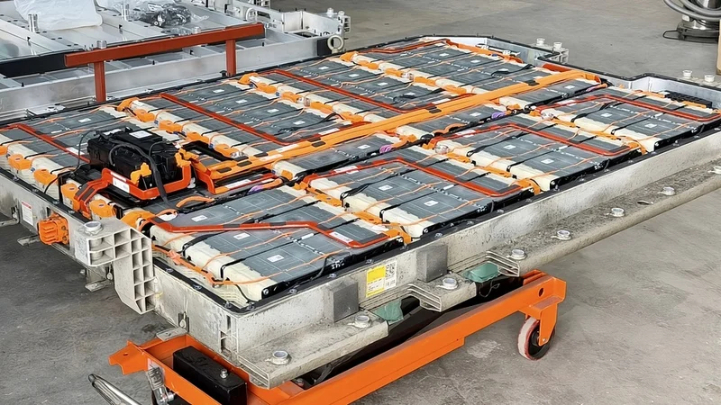
Battery thermal management is the engineering discipline that controls heat generation, heat transfer, and temperature distribution in a battery pack. In electric vehicles, battery energy storage systems, power tools, aircraft prototypes, and high-rate industrial applications, the battery thermal management system is not an accessory. It is a core safety and performance subsystem.
Lithium-ion batteries have a useful but narrow temperature band. At low temperatures, ion transport slows, electrolyte resistance increases, available power decreases, charging must be restricted, and the risk of lithium plating increases. At high temperatures, calendar aging and cycle aging accelerate, internal resistance changes, gas generation risk increases, and abuse tolerance declines. Under severe electrical, mechanical, or thermal abuse, a cell can enter thermal runaway, a self-heating failure mode in which heat generation exceeds heat rejection and the event can propagate to adjacent cells.
A well-designed BTMS does four jobs at once. It removes waste heat during discharge and fast charging. It heats the battery pack in cold ambient conditions. It minimizes hotspots and maintains temperature uniformity across battery cells.
Why Battery Temperature Controls Performance and Safety
Temperature changes the electrochemical behavior of battery cells. A lithium-ion cell is a coupled electrical, chemical, thermal, and mechanical system. The electrodes, electrolyte, separator, current collectors, tabs, and casing all contribute to heat generation and heat transfer. The BTMS must keep this system inside the cell manufacturer's voltage, current, and temperature limits while supporting vehicle or storage-system duty cycles.
The common engineering target for lithium-ion batteries is an operating temperature region near 15-35 °C. But the exact allowable range depends on chemistry, cell format, manufacturer limits, aging target, and load case. Many EV packs can operate outside this window with derating, but operation outside the preferred range carries performance or lifespan penalties.
A practical module target is not only low maximum temperature but also low temperature spread. A 3-5 °C cell-to-cell delta is a common design objective for high-uniformity modules, while cost-sensitive systems may accept a wider gradient if aging and warranty models support it.
High temperatures accelerate degradation mechanisms, including electrolyte oxidation, SEI growth, gas generation, binder degradation, and transition-metal dissolution, in certain chemistries. Low temperatures increase internal resistance, reduce diffusion rates, and can make fast charging unsafe.

The safety margin is cell-specific. Thermal runaway is not triggered at one universal temperature. Abuse calorimetry, nail penetration, overcharge, external heating, and propagation testing show strong dependence on chemistry, state of charge, geometry, aging, heat rejection, and trigger method.
Suggested Reading: How to Charge a Lithium-Ion Battery Safely and Efficiently?
Heat Generation in Battery Cells and Packs
A BTMS starts with a heat-generation model. In the simplest approximation, heat generation scales with I²R, where I is current and R is internal resistance. This is useful for first-order sizing, especially at high discharge or fast-charge power. It is not sufficient for accurate design.
Battery heat generation includes three major components:
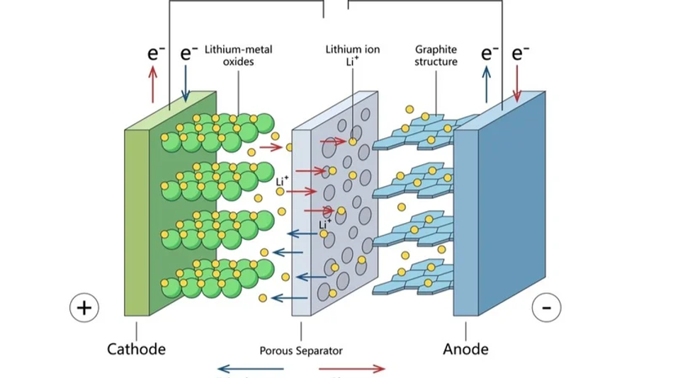
Ohmic and polarization heat from electrical resistance, charge-transfer resistance, ionic resistance in the electrolyte, current collectors, tabs, busbars, and contact interfaces.
Entropic heat from reversible electrochemical entropy change, which can be heating or cooling depending on the state of charge and current direction.
Hysteresis and other irreversible losses are especially relevant in some materials and over dynamic charge-discharge cycles.
A common heat-generation form is:
q_dot = q_irreversible + q_reversible
For a lumped-cell model, the irreversible term is often represented as I(V - U_ocv) or approximated as I^2R when an equivalent internal resistance is known. The reversible term is commonly represented as -I T(dU_ocv/dT), with the sign depending on the current convention. Engineers should not treat the equation as a universal constant. The resistance, open-circuit voltage, entropic coefficient, and heat capacity vary with state of charge, temperature, aging state, and cell design.
At the pack level, the BTMS must account for additional heat sources and heat paths:
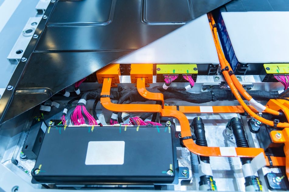
Busbars, welds, interconnects, fuses, contactors, current sensors, and module terminals generate joule heat.
Power electronics and onboard chargers can share thermal loops with the pack.
Cooling plates, adhesives, potting, gap fillers, compression pads, structural members, and enclosure walls create thermal resistance.
Cell-to-cell conduction can be helpful for temperature uniformity but harmful during propagation if not controlled.
Sensor placement can under-read internal cell temperature because surface temperature lags core temperature during transients.
For fast charging, the design load case may be heat rejection at high current, high state of charge, and elevated ambient temperature. For cold-weather charging, the critical load case may be heating the battery pack to a safe charging temperature while minimizing energy consumption. For battery energy storage systems, the load case may be long-duration cycling, solar-shift duty, high-ambient operation, enclosure HVAC failure, or a thermal-runaway propagation test case rather than an aggressive automotive fast-charge event.
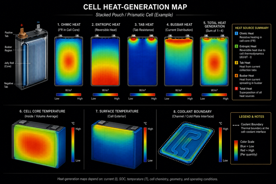
[Diagram: Cell heat-generation map showing ohmic heat, entropic heat, tab heat, busbar heat, cell core temperature, surface temperature, and coolant boundary.]
BTMS Architectures
No battery thermal management system is optimal for every application. The right BTMS depends on power density, allowable cell temperature, temperature uniformity target, packaging, safety concept, field service model, manufacturing process, mass budget, and cost.
Air Cooling
Air cooling uses natural convection or forced air to remove heat from cells or modules. Passive cooling relies on natural convection and conduction to the pack enclosure. Forced-air systems use fans, ducts, plenums, filters, and sometimes cabin-conditioned air.
The advantages are simplicity, low cost, low mass, and the absence of a liquid leak path inside the battery pack. The limitations are low heat capacity and low convective heat transfer compared with liquids. Air cooling can also create strong inlet-to-outlet temperature gradients, so duct design and pressure drop become central design variables. It remains attractive for mild hybrids, low-power EVs, smaller packs, power tools, e-bikes, and cost-sensitive stationary systems.
Suggested Reading: Efficient lithium-air battery under development to speed electrification of vehicles
Liquid Cooling
Liquid cooling usually means indirect cooling: coolant flows through a sealed cold plate, tube, jacket, or channel adjacent to cells or modules. In many EV battery packs, the coolant is a water-glycol mixture, often thermally coupled to a radiator, chiller, heat pump, or cabin HVAC loop. Battery Design describes this architecture as a cooling fluid circulated to and from the battery, with heat removed or added away from the pack using a radiator or heat exchanger.
Cold plates are common in prismatic and pouch-cell modules, often below the cells, between cell rows, or on both sides for high-performance designs. Cylindrical-cell packs may use serpentine tubes, side plates, base plates, or potting paths that conduct heat to a cooling plate.
Liquid cooling improves heat rejection and temperature uniformity relative to air cooling, but it adds pump power, seals, hoses, fittings, leak-detection requirements, corrosion control, freeze protection, service procedures, and crash-safety complexity.
Phase Change Materials and PCM hybrids
Phase change materials absorb heat as latent heat during melting. A PCM can buffer short heat pulses and reduce peak cell temperature without continuous parasitic power. Paraffin-based materials are common research candidates because they have high latent heat and chemical stability, but neat paraffin has low thermal conductivity, often around 0.19-0.35 W/mK, and latent heat around 200-250 J/g in typical waxes.
PCM systems are usually not standalone solutions for high continuous loads. Once the material melts, it must be re-solidified via another heat-rejection path. For this reason, practical PCM architectures often combine phase change materials with aluminum foam, graphite, fins, heat pipes, or liquid cooling.
PCM can improve passive safety and peak shaving, but it adds mass and packaging volume, and flammability, leakage, aging, and manufacturability must be validated.
Suggested Reading: Energy Storage Materials: Lithium from Hot Deep Water
Immersion and Direct Cooling
Immersion cooling places cells or modules in a dielectric fluid. Single-phase immersion circulates liquid through the battery pack and rejects heat through external heat exchangers. Two-phase immersion uses boiling and condensation, although implementation is more complex and less common in production EV packs.
The main benefit is direct contact with cell surfaces and improved temperature uniformity, especially for high-power-density, fast-charging, motorsport, heavy-duty, or special-purpose systems. The main challenges are fluid compatibility with cell seals, adhesives, sensors, plastics, vent gases, and safety devices.
Heat Pipe and Vapor Chamber Concepts
A heat pipe transfers heat through the evaporation and condensation of a working fluid within a sealed device. Heat pipes and vapor chambers can spread local heat from hotspots to a cold plate, enclosure, or radiator interface. They can be useful where direct coolant routing is difficult or where the design needs passive heat spreading with low thermal resistance.
The limitation is that a heat pipe is a heat-transport element, not a heat sink on its own. It must reject heat to air, coolant, a cold plate, or another structure. Orientation sensitivity, freeze behavior, mechanical robustness, crush safety, and integration with cell compression requirements also matter.
Refrigerant and Chiller-based Systems
A refrigerant system uses the vehicle HVAC loop or a dedicated thermal loop to cool the battery either indirectly via a chiller or directly via an evaporator plate. The compressor, expansion device, condenser, evaporator or chiller, heat exchangers, sensors, and valves must be controlled as a system.
Refrigerant cooling can support fast charging and hot-climate operation, but it consumes compressor power and increases controls complexity. In many EVs, the pack liquid loop is coupled to the refrigerant loop through a chiller, allowing the same thermal system to serve the battery, cabin, power electronics, and drive units.
Cooling method | Cooling performance | Temperature uniformity | Complexity | Mass impact | Cost impact | Best-fit applications |
Passive cooling | Low | Low to medium | Very low | Low | Low | Low-power packs, standby systems, small devices |
Forced air cooling | Low to medium | Medium with good ducting | Low | Low to medium | Low | Cost-sensitive EVs, mild hybrids, small modules |
Liquid cooling cold plates | Medium to high | High with good flow balance | Medium to high | Medium | Medium to high | High-performance electric vehicles, fast charging, heavy-duty packs |
PCM or PCM hybrid | Good peak buffering, limited continuous rejection | Medium to high | Medium | Medium to high | Medium | Pulse loads, thermal buffering, passive safety layers |
Heat pipe assisted | Medium heat spreading, needs sink | Medium to high | Medium | Medium | Medium | Hotspot spreading, constrained packaging |
Immersion cooling | High | High | High | Medium to high | High | High power density, fast-charge, motorsport, specialized systems |
Refrigerant or chiller loop | High when integrated correctly | High | High | Medium to high | High | Hot climates, fast charging, integrated EV thermal systems |
Pack-level Heat Paths
Thermal design is controlled by the full thermal resistance chain, not only the coolant. Heat must travel from the cell core to the jelly roll surface or pouch stack, through the can or pouch laminate, across a thermal interface material, into a cooling plate or structure, into coolant, and finally to ambient air through a radiator or refrigerant system.
A simplified conduction resistance is:
R_theta = t / (kA)
where t is thickness, k is thermal conductivity, and A is contact area. Small bond-line thickness and large contact area matter as much as material selection. A high-conductivity cold plate does not compensate for a poor interface gap, trapped air, low compression, warped cell surfaces, or uneven adhesive dispense.
Typical concept-phase values include:
Material or path | Typical thermal conductivity | Design note |
--- | ---: | --- |
Copper busbars | about 380-400 W/mK | High conductivity, high mass and cost |
Aluminum cooling plates or busbars | about 160-230 W/mK depending on alloy | Lower mass than copper, common in pack structures |
Stainless steel | about 14-16 W/mK | Mechanically useful, thermally poor compared with Al or Cu |
Silicone gap fillers and TIMs | about 0.5-5 W/mK in many commercial products | Interface quality and bond-line thickness dominate |
Paraffin PCM | about 0.19-0.35 W/mK without fillers | Needs graphite, fins, foam, or another heat-spreading path |
Cylindrical-cell radial effective path | often order of 1 W/mK | Strong anisotropy, measure actual cell construction |
Metal conductivity values vary by alloy and temperature. Engineering data tables list aluminum near roughly 200 W/mK, copper near roughly 388 W/mK, and stainless steel near roughly 16 W/mK for common grades. Commercial TIM suppliers list battery and electronics gap fillers in ranges such as 0.5-4.8 W/mK, while specific products may be around 2 W/mK.
The most common pack design mistakes are not exotic. They are uneven coolant flow distribution, excessive TIM thickness, poor contact pressure, cell-to-plate tolerance stack-up, uncooled busbars, insufficient tab cooling, and sensor locations that miss the hottest cell.
Suggested Reading: Designing Safer, Higher-Performance Lithium Batteries
Low-temperature Operation, preheating, and BMS control
A BTMS must heat as well as cool. At low temperatures, lithium-ion batteries lose power because charge transfer and ion diffusion slow, electrolyte viscosity rises, and internal resistance increases.
Charging is the critical case because lithium ions may plate out as metallic lithium on the anode rather than intercalate into graphite. This can permanently reduce capacity and increase the risk of internal short-circuiting.
Common low-temperature strategies include:
Pack insulation to reduce overnight heat loss.
Coolant-loop heating using a positive temperature coefficient heater, heat pump, motor/inverter waste heat, or external grid power during plug-in preconditioning.
Direct cell heaters, heater films, or heated cold plates.
Alternating-current internal heating strategies in some research and specialty implementations.
BMS-controlled current limits based on minimum cell temperature, estimated core temperature, state of charge, and plating risk.
The battery management system is the supervisory layer that makes thermal hardware useful. The BMS reads cell temperatures, pack voltage and current, isolation status, contactor state, and sometimes pressure or gas sensor readings. It estimates state of charge, state of health, resistance growth, and allowable charge and discharge power.
A good BMS strategy does not simply wait until a maximum temperature limit is exceeded. It predicts future cell temperature based on current request, coolant temperature, ambient conditions, charge power, and thermal mass.
Thermal Runaway Propagation and Safety Standards
Thermal runaway propagation is the transition from a single-cell failure to a hazard at the module, pack, vehicle, container, or installation level. A BTMS can reduce the probability of entering runaway by controlling temperature, but cooling alone cannot be the only safety layer.
Pack-level propagation prevention uses several mechanisms:
Cell spacing to reduce conductive and radiative heat transfer.
Thermal barriers, mica sheets, ceramic papers, aerogels, intumescent materials, and insulating foams.
Controlled vent paths that direct gases away from passengers, service personnel, sensitive electronics, and adjacent cells.
Module partitions and sacrificial vent volumes.
Electrical segmentation, fusing, contactors, and short-circuit protection.
Flame arresting and enclosure pressure relief where validated.
BMS fault detection using voltage, temperature, pressure, gas, current imbalance, and isolation monitoring.
Standards provide test frameworks. UN 38.3 covers lithium cell and battery transport testing, including altitude simulation, thermal cycling, vibration, shock, external short circuit, impact or crush, overcharge, and forced discharge test categories. IEC 62660-2 specifies reliability and abuse testing procedures for secondary lithium-ion cells and cell blocks for electric road vehicle propulsion, while IEC 62660-3 defines safety requirements and acceptance criteria for cells used in EV battery pack systems.
UL 2580 applies to batteries for use in electric vehicles, and UL Solutions lists EV battery testing activities such as thermal propagation by crush, heater, nail, overcharge, short circuit, or flame, as well as high- and low-temperature endurance, vibration, shock, gas analysis, and external fire exposure. For stationary battery energy storage systems, UL 9540A is a test method for evaluating thermal runaway fire propagation and fire or explosion hazard characteristics at the ESS scale.
The practical point is simple: design the BTMS to prevent abuse, then design the battery pack to tolerate credible abuse.
Suggested Reading: What Is LiFePO4? Engineering Guide to Lithium Iron Phosphate Batteries
Practical Design Tradeoffs
A battery thermal management system is always a tradeoff among thermal performance, energy consumption, mass, volume, cost, safety, durability, manufacturability, and serviceability.
In electric vehicles, liquid cooling dominates high-performance applications because it supports high continuous power, fast charging, good temperature uniformity, and integration with cabin HVAC, the radiator, chiller, heat pump, power electronics, and drive-unit cooling. The penalty is complexity. The pack must manage coolant sealing, corrosion, freeze protection, crash loads, pump reliability, degassing, service fill, leak detection, and end-of-line testing.
Air cooling is less capable but attractive where the heat flux is moderate. It reduces the part count and prevents liquid from entering the pack. It can be the right choice for small packs, low-cost vehicles, mild climates, and stationary modules operating at conservative C-rates.
PCM improves transient peak-temperature control and reduces fan or pump energy consumption during short pulses, but it does not eliminate the need for a heat rejection path. Once melted, the PCM stores heat that must later be released from the battery pack.
Battery energy storage systems have different priorities. Stationary systems may have more space for HVAC, fans, liquid loops, fire barriers, and service access. They may also face stricter installation code reviews, fire department concerns, explosion-control requirements, and thermal-runaway propagation testing.
A practical BTMS design workflow is:
Define the cell chemistry, format, voltage window, current limits, allowable operating temperature, aging target, and safety limits.
Measure heat generation versus C-rate, temperature, state of charge, and aging.
Build a cell-to-pack thermal model that includes anisotropic cell properties, tabs, busbars, TIMs, coolant, enclosure, and ambient boundary conditions.
Compare air cooling, liquid cooling, PCM, heat pipe, refrigerant, and immersion options against the real duty cycle.
Validate with module thermal mapping, coolant-flow tests, hot and cold chamber tests, fast-charge tests, vibration and shock, leak testing, and abuse or propagation testing.
Integrate BMS controls, diagnostics, derating, preconditioning, and service procedures before design freeze.
Suggested Reading: Why Edge AI for EV Battery Management
Conclusion
Battery thermal management is a system-level discipline. The BTMS must regulate the battery pack across hot weather, low temperatures, fast charging, high-power discharge, aging, manufacturing variation, and credible fault cases. It must remove heat, add heat, maintain temperature uniformity, reduce hotspots, protect lifespan, and work with the BMS to keep cells inside their safe operating region.
The dominant production pattern in high-performance electric vehicles is indirect liquid cooling via cold plates or similar structures, typically integrated into broader vehicle thermal loops that include a radiator, heat exchangers, a chiller, and sometimes a heat pump. Air cooling remains viable where power density and cost targets allow. PCM, heat pipe, immersion, and refrigerant-based designs are important tools, but each must be justified by duty cycle, safety case, validation burden, and manufacturability.
FAQ
What is a battery thermal management system?
A battery thermal management system, or BTMS, is the hardware and control strategy used to regulate battery temperature. It may include cold plates, fans, ducts, coolant, pumps, heat exchangers, heaters, insulation, sensors, valves, a radiator, a chiller, and BMS software. Its job is to keep battery cells within the specified operating temperature range, reduce temperature gradients, support charging and discharge power, and improve safety and lifespan.
What temperature range is best for lithium-ion batteries?
A common engineering target for lithium-ion batteries is approximately 15-35 °C for strong performance and aging behavior, with tighter targets for high-performance EV packs. Many cells can operate outside this range, but the BMS may reduce charge or discharge power. At low temperatures, internal resistance rises and lithium plating risk increases during charging. At high temperatures, degradation accelerates and abuse tolerance can decline.
Why is liquid cooling common in electric vehicles?
Liquid cooling is common because liquids have far higher volumetric heat capacity than air and can move heat efficiently from dense battery pack structures to a radiator, chiller, or heat pump loop. Liquid cooling also improves temperature uniformity during fast charging and high-power discharge. The drawbacks are higher cost, mass, complexity, pump energy consumption, leak risk, and more demanding validation.
How do phase change materials help battery thermal management?
Phase change materials, or PCM, absorb heat as latent heat during melting. This can reduce peak temperature during short high-power events and improve passive thermal buffering. PCM is less effective for continuous heat loads unless it is paired with a heat rejection path such as liquid cooling, fins, graphite, aluminum foam, or a heat pipe. Designers must validate leakage, flammability, mass, aging, and re-solidification time.
What standards apply to EV battery thermal safety?
Relevant standards and test frameworks include UN 38.3 for lithium battery transport testing, IEC 62660 for EV propulsion lithium-ion cell performance, reliability, abuse, and safety requirements, and UL 2580 for batteries used in electric vehicles. Thermal propagation testing may use triggers such as heater, nail, overcharge, short circuit, crush, or flame depending on the test plan and standard. Stationary systems often involve UL 9540A.
References
National Renewable Energy Laboratory, Tools for Designing Thermal Management of Batteries in Electric Drive Vehicles
MDPI Energies, A Review of Thermal Management and Heat Transfer of Lithium-Ion Batteries
MDPI Batteries, Thermal Runaway in Lithium-Ion Batteries: A Review of Mechanisms, Prediction Approaches, and Mitigation Strategies
UNECE, UN Manual of Tests and Criteria, Rev. 8 and Amendment 1 (lithium battery transport testing, section 38.3).
IEC, IEC 62660-2:2018 and IEC 62660-3:2022, secondary lithium-ion cells for electric road vehicle propulsion: 62660-2 and 62660-3.
UL Solutions, EV Battery Testing for Compliance with Regulatory Requirements and Standards and UL 9540A Test Method for Battery Energy Storage Systems.
in this article
1. Introduction2. Why Battery Temperature Controls Performance and Safety3. Heat Generation in Battery Cells and Packs4. BTMS Architectures5. Pack-level Heat Paths6. Low-temperature Operation, preheating, and BMS control7. Thermal Runaway Propagation and Safety Standards8. Practical Design Tradeoffs 9. Conclusion10. FAQ11. References