Arduino Nano Pinout: Complete Technical Reference
Arduino's Nano series packs the power of an Arduino Uno into a tiny, breadboard-friendly form factor. This guide covers every pin, electrical limit, and protocol on the classic Nano and its Nano Every and Nano ESP32 variants.

22 May, 2026. 11 minutes read
Key Takeaways
The classic Arduino Nano exposes 30 pins: 14 digital I/O (D0-D13), 8 analog inputs (A0-A7), power rails (VIN, 5 V, 3.3 V, GND), and Reset. Analog pins A6 and A7 are analog-only and cannot be used as digital I/O.
The ATmega328P Nano runs at 5 V with a recommended VIN range of 7-12 V. It offers both 5 V and 3.3 V output rails. The 3.3 V rail is limited to 50 mA.
Current limits: Each GPIO can source or sink up to 20 mA (absolute max 40 mA). Total current through VCC and GND must not exceed 200 mA.
The Nano implements one UART (D0/D1), SPI (D10-D13: SS, MOSI, MISO, SCK), and I²C (A4/A5: SDA, SCL). Six digital pins (D3, D5, D6, D9, D10, D11) provide PWM at ~490 Hz or ~980 Hz depending on the timer.
The Nano Every uses an ATmega4809, runs at 20 MHz with 48 KB Flash, and keeps 5 V logic. The Nano ESP32 uses an ESP32-S3, operates at 3.3 V, and adds Wi-Fi and Bluetooth. Its GPIOs source up to 40 mA and sink 28 mA.
Introduction
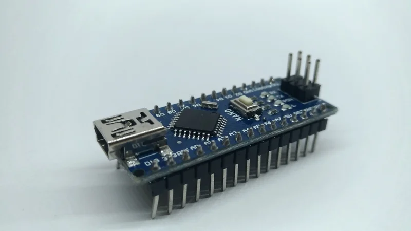
The Arduino Nano condenses the functionality of a full-size Uno into a board just 45 × 18 mm and weighing about 7 grams. It easily fits on breadboards and enclosures, allowing makers to use it for wearables, robotics, IoT prototypes, and countless embedded products.
For engineering students and DIY hobbyists, the Arduino Nano offers high value with its affordability and community support. Yet the Nano's compactness makes every pin assignment matter. Connecting a sensor to the wrong pin can disable serial communication or overload a regulator. So, to help you understand the pinout, this guide will take you through the Arduino Nano pinout in detail, and explains its electrical limits, maps protocol lines to microcontroller peripherals, and compare the classic and modern Nano variants.
Arduino Nano Overview
For a compact-sized board, the Arduino Nano delivers some powerful features. Here are some key aspects to consider:
Arduino Nano Board Specifications
The Arduino Nano board runs on the ATmega328P, an 8-bit AVR microcontroller, which features 32 KB Flash, 2 KB SRAM, and 1c KB EEPROM. It runs at 16 MHz and operates between 2.7 V and 5.5 V.
The ATmega328P provides:
23 programmable I/O lines
03 timers (two 8-bit and one 16-bit)
A 10-bit ADC with eight channels
Communication interfaces for UART, I²C, and SPI communication.
There are dedicated headers installed on the board that connect to these functions. Also, there is an on-board USB-to-serial chip, voltage regulators, and protection circuitry
Recommended Reading: Understanding 8-bit vs. 32-bit Microcontrollers: A Guide for Engineers
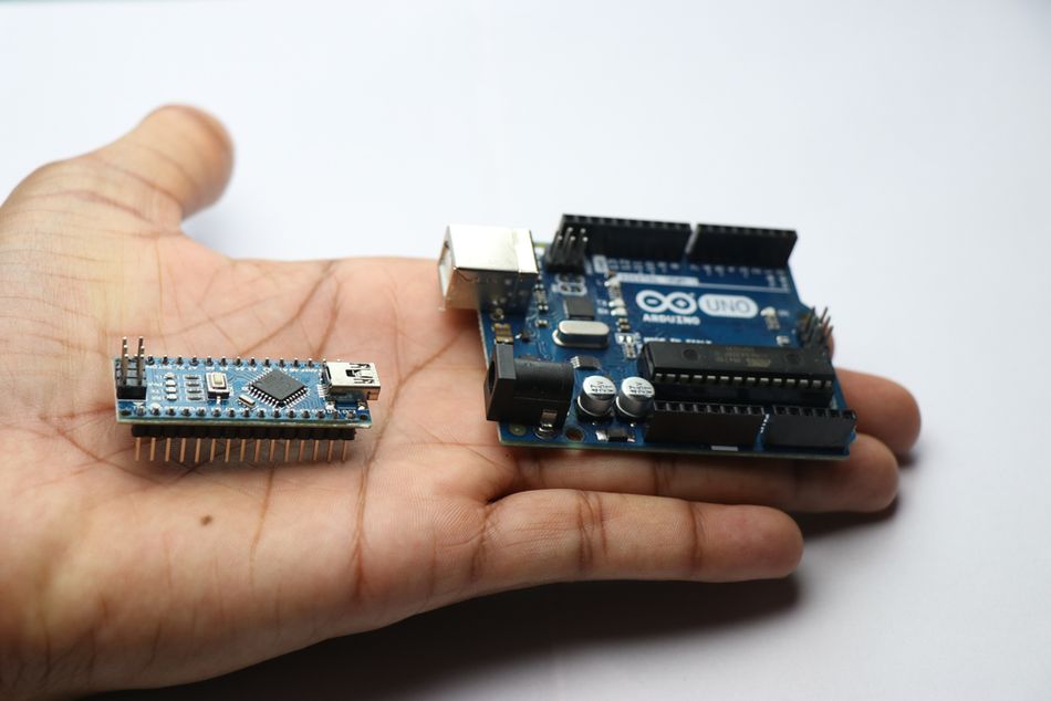
Arduino Nano vs Uno
Arduino Uno is one of the most commonly used Arduino boards. Its applications range from DIY projects to industrial applications. The Nano board features two extra analog inputs (A6 and A7) and its mini-USB port make it better suited for compact prototypes.
The board can be powered via USB, VIN, or the 5 V pin with external power. Recommended VIN is 7-12 V and the on-board regulator outputs 5 V. A secondary regulator provides 3.3 V at up to 50 mA. A resettable polyfuse protects the board when powered via USB.
While the Nano board may be small, it houses all the functionalities of the Uno board. Here are some key comparison analytics.
Board | MCU | Logic | Digital I/O | Analog Inputs | PWM | Flash Memory / SRAM | Footprint |
Nano (ATmega328P) | ATmega328P | 5 V | 14 (D0-D13) | 8 (A0-A7) | 6 (D3, D5, D6, D9, D10, D11) | 32 KB / 2 KB | 45 × 18 mm |
Uno R3 | ATmega328P | 5 V | 14 (D0-D13) | 6 (A0-A5) | 6 (D3, D5, D6, D9, D10, D11) | 32 KB / 2 KB | 68.6 × 53.4 mm |
Arduino Nano Dimensions and Form Factor
The Nano's 45 mm length and 18 mm width allow it to straddle a breadboard, exposing pins on both sides. Its header rows use 2.54 mm spacing and are pre-soldered on most boards. The weight of roughly 7 grams makes it suitable for wearable designs. Mounting holes are provided only on variants with castellated edges or additional carriers.
Suggested Reading: Selecting a microcontroller (MCU) for your IoT product
Full Pinout Reference
The classic Arduino Nano uses two 15-pin headers. Each pin's function is described below. The ICSP header, located on the underside of some boards, duplicates the SPI pins for programming.
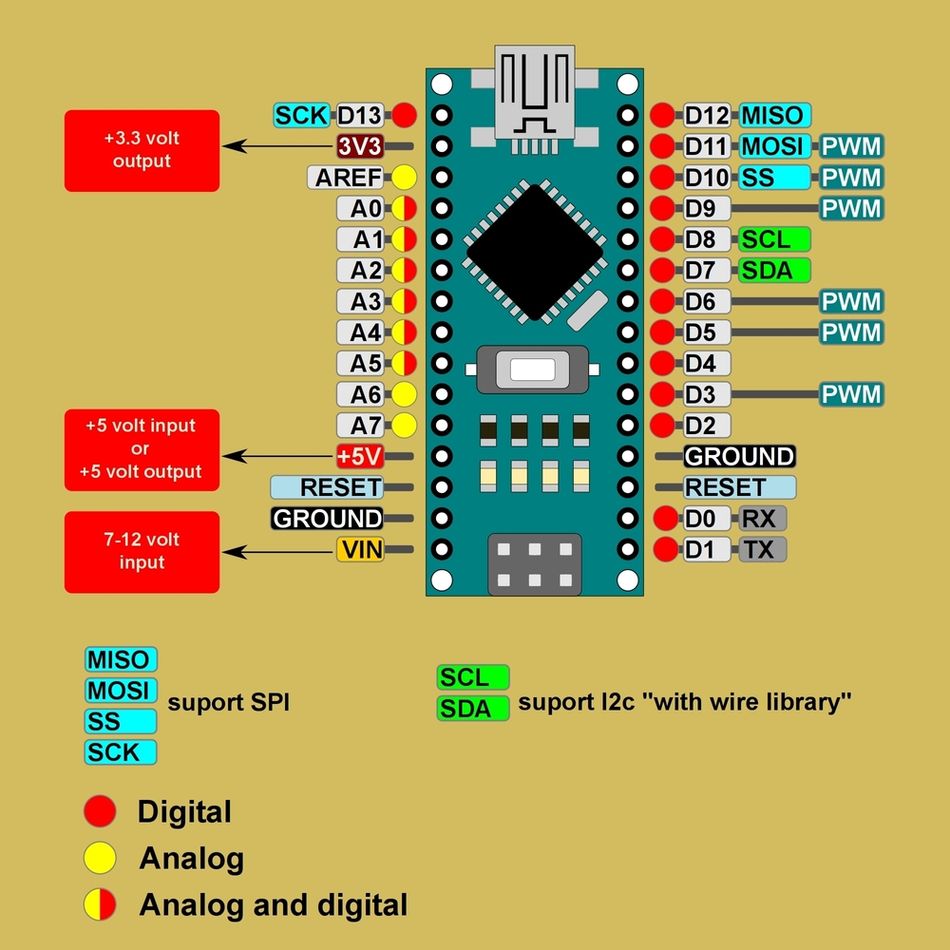
Fig 2: Arduino Nano Pinout summary
Pin Assignments and Functions
Label | ATmega328P port | Function | Typical uses |
VIN (Pin 30) | - | Unregulated input (7-12 V) | Supply board via external adapter |
5V (Pin 27) | VCC | Regulated 5 V output/input | Power sensors and modules (up to ~200 mA total) |
3.3V (Pin 25) | - | 3.3 V output (max 50 mA) | Low-voltage devices |
GND (Pins 4, 5, 14, 20, 28) | GND | Ground return | Reference point for all signals |
Reset (Pin 29) | RESET | Active-low reset input | Reset the MCU externally |
D0 / RX (Pin 2) | PD0 | UART receive | Serial communication |
D1 / TX (Pin 3) | PD1 | UART transmit | Serial communication |
D2 / INT0 (Pin 4) | PD2 | Digital I/O, external interrupt 0 | Pushbuttons, interrupts |
D3 / INT1 / PWM (Pin 5) | PD3 | Digital I/O, PWM (Timer2), interrupt 1 | Motor control, LED dimming |
D4 (Pin 6) | PD4 | Digital I/O | General purpose |
D5 / PWM (Pin 11) | PD5 | Digital I/O, PWM (Timer0) | Motor control, LED dimming |
D6 / PWM (Pin 12) | PD6 | Digital I/O, PWM (Timer0) | Motor control, LED dimming |
D7 (Pin 13) | PD7 | Digital I/O | General purpose |
D8 (Pin 14) | PB0 | Digital I/O | General purpose |
D9 / PWM (Pin 15) | PB1 | Digital I/O, PWM (Timer1) | Servo control |
D10 / PWM / SS (Pin 16) | PB2 | Digital I/O, PWM (Timer1), SPI SS | Chip-select for SPI devices |
D11 / PWM / MOSI (Pin 17) | PB3 | Digital I/O, PWM (Timer2), SPI MOSI | SPI master-out slave-in |
D12 / MISO (Pin 18) | PB4 | Digital I/O, SPI MISO | SPI master-in slave-out |
D13 / SCK (Pin 19) | PB5 | Digital I/O, SPI clock, built-in LED | SPI bus clock, status LED |
A0-A5 (Pins 23-26, 9-10) | PC0-PC5 | Analog inputs, 10-bit ADC; also digital I/O | Sensors, reading voltages |
A6-A7 (Pins 8, 7) | ADC channels | Analog inputs only | Additional sensor inputs |
AREF (Pin 24) | - | Analog reference input | External reference for ADC |
ICSP header | PB3/PB4/PB5, VCC, GND, RESET | SPI signals for programming | In-system programming, bootloader |
Power Pins and Voltage Considerations
VIN and Raw Input
The VIN pin supplies unregulated voltage to the on-board linear regulator. The official pinout document specifies a recommended input range of 7-12V . The absolute voltage limits are approximately 6-20 V, but exceeding 12 V increases heat dissipation and reduces efficiency.
VIN feeds a 5V LDO, so drawing high current from the 5V rail while powered from VIN may cause a voltage sag.
5 V Rail
The 5V pin (Pin 27) can either supply regulated 5V to the board (for example, from a USB battery pack) or output 5V when the board is powered via USB or VIN.
When powered via USB, the 5V rail can provide up to roughly 500 mA minus the board's own consumption, limited by the polyfuse and USB current. The ATmega328P's I/O pins draw from this rail, and the total current through VCC and GND must not exceed 200 mA .
3.3 V Rail
The Nano includes a separate 3.3 V regulator. This rail can supply up to 50 mA. Use it for low-voltage sensors or external modules such as accelerometers. Exceeding this current can cause thermal shutdown.
Ground and Reset
Multiple GND pins provide return paths. For best results, connect sensor grounds to one of these pins to minimize noise. The Reset pin resets the MCU when pulled low. A 10 kΩ pull-up resistor on the board keeps it high, and an external reset button can be connected between RESET and GND.
Suggested Reading: What Is Ground in a Circuit? Understanding Grounding Concepts and Implementations
Digital I/O Pins
Numbering and General Capabilities
Arduino Nano has 14 digital I/O pins labeled D0 through D13. They operate at 5 V logic and can each source or sink up to 20 mA (absolute maximum 40 mA). All digital pins support digitalRead() and digitalWrite() operations. Moreover, some of them have additional functions:
UART: Pins D0 (RX) and D1 (TX) connect to the ATmega328P's USART. These lines are used by the USB-to-serial converter, so avoid connecting external devices to D0 or D1 when using the serial monitor.
External interrupts: D2 (INT0) and D3 (INT1) trigger interrupts on rising, falling, or change events.
PWM: Six digital pins provide Pulse Width Modulation via analogWrite() function. The PWM pins control motors or LED brightness. On the Nano, pins 3, 9, 10, and 11 use a prescaler that yields ~490 Hz, while pins 5 and 6 use a different timer for ~980 Hz .
PWM Frequencies
PWM pin | Timer | Default frequency |
D3 (OC2B) | Timer2 | 490 Hz |
D5 (OC0B) | Timer0 | 980 Hz |
D6 (OC0A) | Timer0 | 980 Hz |
D9 (OC1A) | Timer1 | 490 Hz |
D10 (OC1B) | Timer1 | 490 Hz |
D11 (OC2A) | Timer2 | 490 Hz |
Changing these frequencies requires adjusting the timer prescalers. Modifying Timer0 affects functions such as millis() and delay() .
Suggested Reading: What Is a PWM Signal? Fundamentals and Practical Applications for Engineers
Built-in LED and SPI Pins
Pin D13 connects to the on-board LED and also acts as the SPI SCK line. When using the SPI interface, avoid driving the LED at the same time to prevent signal distortion.
Pins D11 (MOSI) and D12 (MISO) complete the SPI bus, with D10 typically used as SS (slave-select) for peripherals.
The Nano uses a separate hardware ICSP header that exposes MOSI, MISO, SCK, VCC, GND, and RESET for programming the bootloader via Arduino IDE.
Current and Protection
Although each I/O pin can handle up to 40 mA, designers should limit current to 20 mA to prolong the microcontroller's life and avoid dropping voltage on the 5V rail. . It is advised to use external drivers or transistors for high-current loads, and include current-limiting resistors when driving LEDs.
Analog Input Pins
A0-A5 (Multipurpose)
The Nano provides eight analog inputs labeled A0 through A7. Channels A0-A5 connect to the ATmega328P's 10-bit ADC, which converts input voltages between 0 V and the analog reference (default 5 V) into values from 0 to 1023. Change the reference by connecting a voltage (0-5 V) to the AREF pin and calling analog Reference.
The analog inputs can also serve as digital pins with numbers 14-19. Their digital capabilities are identical to D0-D13. Pins A4 and A5 double as I²C SDA and SCL lines .
A6-A7 (Analog-Only)
Unlike the other analog pins, A6 and A7 connect only to the ADC multiplexer and lack digital circuitry. They cannot be used for digitalRead() or digitalWrite(), nor do they have internal pull-ups. These pins are ideal for reading additional sensors when all other analog inputs are used.
ADC Resolution and Sampling
The ATmega328P's ADC is 10 bits, providing 1024 discrete steps . Its sampling rate is approximately 9 kS/s with the default prescaler. For improved noise performance, use the built-in bandgap reference (1.1 V) or an external precision reference via AREF.
Add a bypass capacitor (approximately 100 nF) between AREF and GND when using an external reference.
Further Reading: Analog & digital: best of both worlds in one energy-efficient system
Communication Protocols
UART Communication
The Nano exposes a single UART on pins D0 (RX) and D1 (TX). This is connected to the onboard USB-to-serial converter, enabling programming and serial monitor. When using hardware serial for other purposes (connecting a GPS module, for example), avoid using the serial monitor or use the SoftwareSerial library on other pins.
SPI (Serial Peripheral Interface)
SPI allows high-speed communication with devices like SD cards, displays, or sensors. On the Nano, D13 is SCK, D12 is MISO, D11 is MOSI, and D10 is SS . The ATmega328P acts as the master. Use SPI.begin() to configure the interface and choose appropriate clock dividers to meet peripheral requirements. When programming the bootloader via the ICSP header, ensure no peripherals are connected to these pins.
Suggested Reading: UART vs SPI: A Comprehensive Comparison for Embedded Systems
I²C (Two-Wire Interface)
I²C uses a shared bus with open-drain lines. The Nano's A4 (SDA) and A5 (SCL) provide the interface . Pull-up resistors (4.7 kΩ-10 kΩ) to 5 V are required. Some breakout boards include them.
The ATmega328P supports standard (100 kHz) and fast mode (400 kHz). Use Wire.begin() to initialize. A4 and A5 remain analog-capable when not used for I²C.
ICSP Header
The In-Circuit Serial Programming (ICSP) header duplicates the SPI signals along with 5 V, GND, and RESET. It is used by USBasp or Arduino-as-ISP programmers to burn bootloaders or upload firmware when the main USB interface is unavailable. The pin numbering on this header is: 1=MISO, 2=5 V, 3=SCK, 4=MOSI, 5=RESET, 6=GND.
Recommended Reading: I2C vs SPI vs UART: A Comprehensive Comparison
Nano Variants and Differences
Nano Every
The Nano Every is an evolution of the classic Nano with the same form factor and pinout. It replaces the ATmega328P with an ATmega4809, a megaAVR microcontroller. Compared with the classic Nano, the Every offers 48 KB Flash, 6 KB SRAM, and a 20 MHz clock.
The board operates at 5 V logic and retains 14 digital pins and 8 analog inputs, but only five PWM pins (D3, D5, D6, D9, D10). The Nano Every board has a DC current limit of 20 mA per I/O pin and a 3.3 V rail supplying 50 mA, because it uses a different microcontroller, registers and memory maps differ. Libraries requiring direct port access may need adaptation.
Parameter | Nano (ATmega328P) | Nano Every (ATmega4809) |
Logic voltage | 5 V | 5 V |
MCU clock | 16 MHz | 20 MHz |
Flash / SRAM | 32 KB / 2 KB | 48 KB / 6 KB |
Digital pins | 14 (6 PWM) | 14 (5 PWM) |
Analog inputs | 8 | 8 |
Input voltage | 7-12 V | 6-21 V |
3.3 V current | 50 mA | 50 mA |
Nano ESP32
The Nano ESP32 brings Arduino's Nano form factor to the ESP32-S3 platform. The product reference manual explains that it uses a dual-core Xtensa LX7 processor up to 240 MHz, offers 384 kB ROM, 512 kB SRAM, and 16 MB Flash.
The board operates at 3.3 V, supports Wi-Fi and Bluetooth LE, and can be powered via USB-C or VIN (6-21 V) . It exposes 14 digital pins and eight analog inputs accessible in RTC mode, mapped to ESP32 GPIOs . Each GPIO can source up to 40 mA and sink up to 28 mA .
Parameter | Nano (ATmega328P) | Nano ESP32 |
MCU | ATmega328P | ESP32-S3 (NORA-W106) |
Operating voltage | 5 V | 3.3 V |
Processor speed | 16 MHz | Up to 240 MHz |
Wi-Fi / Bluetooth | None | Wi-Fi + BLE |
Digital pins | 14 | 14 (up to 21 functions) |
Analog inputs | 8 (10-bit) | 8 (ADC in RTC mode) |
Default logic level | 5 V | 3.3 V |
PWM frequency | ~490/980 Hz | Configurable via ESP32 timers |
Current per GPIO | 20 mA recommended | 40 mA source / 28 mA sink |
USB connector | Mini-B | USB-C |
Because the Nano ESP32 uses 3.3 V logic, connecting 5 V sensors directly can damage the pins. Use level-shifters or voltage dividers. It also supports additional protocols such as I²S (audio) and CAN (TWAI) , making it suitable for IoT and edge computing.
Conclusion
The Arduino Nano condenses powerful features into a tiny footprint. Its 30 pins provide digital I/O, analog measurement, PWM outputs, and communication interfaces that mirror those on the larger Uno. The board's 5 V logic, 7-12 V input range, and 10-bit ADC make it compatible with a wide range of sensors and modules.
Newer variants like the Nano Every and Nano ESP32 maintain the Nano form factor but offer different microcontrollers, clock speeds, and operating voltages. The Every increases Flash and SRAM while retaining 5 V logic , whereas the ESP32 version introduces dual-core processing, Wi-Fi and Bluetooth connectivity, and 3.3 V logic .
FAQ
What voltage does the Arduino Nano use?
The classic Nano operates at 5 V logic. Power it via USB (5 V), VIN (7-12 V recommended), or the 5 V pin. A 3.3 V regulator provides up to 50 mA for low-voltage peripherals . The Nano ESP32, by contrast, uses 3.3 V logic and must not be driven with 5 V signals .
Which Arduino Nano pins support PWM?
Six digital pins on the classic Nano support PWM: D3, D5, D6, D9, D10, and D11. Pins 3, 9, 10, and 11 output about 490 Hz. Pins 5 and 6 output about 980 Hz by default . The Nano Every offers PWM on D3, D5, D6, D9, and D10 . The Nano ESP32 allows PWM on almost any GPIO via configurable timers.
How many analog pins does the Arduino Nano have?
The classic Nano exposes eight analog inputs: A0-A7. A0-A5 can also be used as digital pins. A6 and A7 are analog-only . Each channel uses the ATmega328P's 10-bit ADC, providing values from 0 to 1023 .
What are the I²C pins on the Arduino Nano?
A4 (SDA) and A5 (SCL) form the I²C bus . Pull-up resistors (4.7 kΩ-10 kΩ) to 5 V are required. These pins double as analog inputs and remain usable for analogRead() when I²C is not active.
Can I power the Arduino Nano with a 9 V battery?
Yes. Connect a 9 V battery to the VIN pin. The onboard regulator will drop the voltage to 5 V. However, 9 V alkaline batteries provide limited current and will drain quickly. Consider using a 7-12 V DC adapter or a 5 V regulated supply for projects requiring more than a few tens of milliamps .
What is the maximum current per pin on the Arduino Nano?
Each I/O pin can safely source or sink 20 mA (absolute maximum 40 mA) . The total current drawn from all pins should not exceed 200 mA . Exceeding these limits can damage the microcontroller. For higher-current loads, use external drivers or transistors.
References
Arduino, “Arduino Nano Documentation,” Arduino. [Online].Available: https://docs.arduino.cc.
NextPCB, “The Ultimate Guide to Arduino Nano Pinout,” NextPCB. [Online]. Available: https://www.nextpcb.com/blog/arduino-nano-pinout
Last Minute Engineers, “Arduino Nano Pinout Reference,” Last Minute Engineers. [Online]. Available: https://lastminuteengineers.com/arduino-nano-pinout/
Spiceman, “Arduino Nano Every Specifications/Functions,” Spiceman. [Online]. Available: https://spiceman.net/arduino-nano-every/
Mouser Electronics, “Arduino® Nano ESP32 Datasheet,” ABX00083 datasheet, Mouser Electronics. [Online]. Available: https://www.mouser.com/pdfDocs/ABX00083-datasheet.pdf