Single Actuator Prosthetic Hand
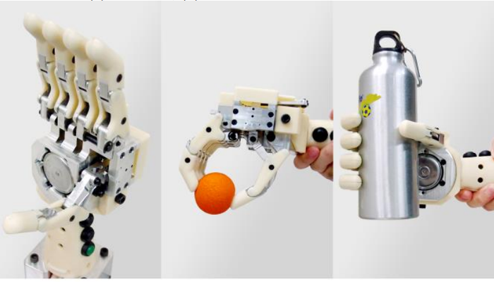
A five-fingered prosthetic hand that has multiple grip patterns with the use of only one actuator. This prosthetic hand is capable of performing one neutral position and two grip patterns that are dominant in daily life tasks. Different move patterns are achieved through the use of multiple sets of rigid four-bar linkages which provide different motions to fingers and thumb when the mechanism is actuated in the opposite direction.


Technical Specifications
| Length | 189 |
| Width | 97 |
| Hand circumference | 295 |
| Joints | 38 |
| Board size | 64 x 41 x 21 |
| Actuator | |
| stall torque of 0.239 | |
| Transmission | |
| Power |
Overview
This prosthetic hand is capable of performing one neutral position and two grip patterns that are dominant in daily life tasks. Different move patterns are achieved through the use of multiple sets of rigid four-bar linkages which provide different motions to fingers and thumb when the mechanism is actuated in the opposite direction.
The prosthetic hand which has been developed has one degree of freedom and is an improvement from conventional single-actuator hands, which can only perform open/close motion. For this reason, this design could be an alternative answer of improvement between conventional and multiple Degree of Freedom prosthetic hands.
Design
In this research, we propose a new concept of mechanism that uses the ability to actuate in both directions of electrical motor to provide different hand motion outputs. An actuator is placed inside the hand with rotational axis perpendicular to the palm, and this mechanism connects to four fingers and separately to thumb as in Fig. 2.

Figure 2. Prosthetic hand mechanism concept. An actuator is placed within palm. The mechanism connects to four fingers and separately to thumb. Precision grip and power grip would occur when mechanism is actuated in different directions.
Precision grip occurs when the mechanism is actuated in one direction and power grip occurs when the mechanism is actuated in the opposite direction. With this design, the prosthetic hand would be able to perform a precision grip, power grip, and open hand position (neutral position) with only a single actuator, unlike conventional single actuator prosthetic hand that has only simple open/close motion
Fingers & Thumb Mechanism Design
Human fingers have three joints, whereas thumb has two joints outside the palm. This allows fingers to curl and wrap around objects with stability. In prosthetic hands design, fingers with three separate rigid linkages like human fingers may not have satisfying functions that justify with the complexity. Fewer joints and less degrees of freedom are more practical and feasible.
One degree of freedom prosthetic fingers with two joints coupled together have been used for a long time because they could provide adequate function and cosmetic appearance. For example, the Bebionic hand uses four-bar linkage with a linear motion plastic rod connected to distal link, and the iLimb hand uses two rigid linkages connected by a tendon driven through bearing surface .

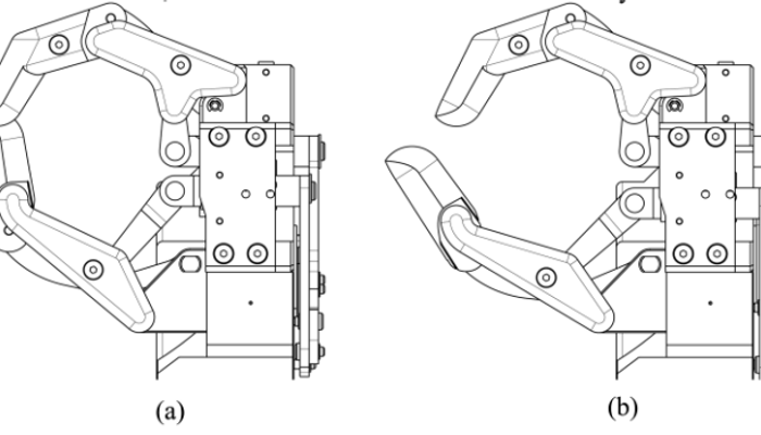
Figure 3. Kinematic diagram of fingers and thumb mechanism. (a) Open hand position, (b) Precision grip position, (c) Power grip position.
There are certain similarities in finger mechanisms found throughout many prosthetic hands. Joseph T. Belter measured the angle ratio between the Metacarpophalangeal joint (MCP) and the Proximal interphalangeal joint (PIP) of commercial prosthetic fingers to be between 1.09 and 1.27.
This research designs one degree of freedom prosthetic fingers and thumb with MCP and PIP as the rotating joint. Distal interphalangeal joint (DIP) is fixed with intermediate phalange at 40 degree angle. The MCP/PIP angle ratio is 1.15, which allows fingers and thumb to perform both precision and power grips. Each finger and thumb contains 3 rigid links in the form of four-bar linkage with an additional drive link connected from distal link to move on a prismatic joint as in Fig. 3.

Figure 4. Index, middle, and thumb mechanisms. Each finger is a four-bar linkage which has PIP and MCP as rotating joints. (a) Precision grip position, (b) Power grip position.
Prismatic joint position of fingers and thumb are used as indicators of each grasp pattern. That is, fingers and thumb prismatic joints would be at F0 and T0 positions when in the open hand position as in Fig. 3a, at the F1 and T1 positions for precision grip position as in Fig. 3b, and at the F2 and T2 positions for open hand position as in Fig. 3c, respectively.
All four fingers (index, middle, ring, and little finger) have identical dimensions for the purpose of less design complexity. Index and middle finger tips would touch the thumb tip if both fingers and thumb are flexed simultaneously as in Fig. 4a, whereas the finger tips would touch the inside of the palm if fingers flexion occur earlier than thumb flexion as in Fig. 4b.
Hand Mechanism Design
This research proposes a design of hand mechanism which could provide different motions of fingers and thumb when actuated in each direction, with a mechanism comprised of 2 sets of rigid linkages separately connected to four fingers and thumb.
The first set of mechanisms connected to all four fingers provides simultaneous motion for the four fingers. This is a crank-slider mechanism which has identical output profiles for both directions of actuation. The second set of mechanisms connected to the thumb is a dwell mechanism inspired by single-dwell six-bar mechanism which uses coupler point of four-bar mechanism as the moving path of a drive link connected to the thumb as in Fig. 5.

Figure 5. Hand mechanism consists of two major mechanisms: crank-slider mechanism connected to four fingers and dwell four-bar mechanism connected to thumb. Coupler point of thumb mechanism is used to provide different motions when moved along opposite directions.
This dwell mechanism output motion is similar to a camshaft but consists of only rigid linkages and joints which have less wear from friction than camshaft design. From Fig. 5, Line F0, F1, and F2 represent finger prismatic joint positions corresponding to each grip pattern, which is open hand, precision grip, and power grip, respectively, whereas line T0, T1, and T2 represent thumb prismatic joint positions of each grip pattern in the same manner.
These lines are objective positions when the mechanism performs each grip pattern; the mechanism would start from F0 and T0 positions then move simultaneously to F1 and T1 positions to perform a precision grip or move to F2 and T2 positions with delayed thumb motion to perform a power grip.
Hand Mechanism Synthesis
After the mechanism concept is decided, mechanism synthesis process is required to determine the dimensions of mechanism with desired motion. This synthesis process starts with the first set of mechanisms connected to four fingers which must have identical output motion for both actuated directions; this type of motion could be achieved by a simple crank-slider mechanism. The mechanism which could fit into hand space and have high mechanical advantage is designed as in Fig. 6.

Figure 6. Fingers mechanism connected to four fingers. This mechanism provides identical motions for each actuated direction. Line F0, F1, and F2 are positions of prismatic joint of mechanism at each grip pattern.
The second set of mechanisms is the thumb mechanism which uses coupler point of four-bar linkage mechanism to achieve different outputs for each actuated direction. The dimensions of this mechanism must be computed to achieve desired performance.
In this computation process, design parameters which have important effect on mechanism motions are required to be computed for the best possible outcome. These parameters, such as linkage lengths, positions, and angles are defined as in Fig. 7. MATLAB Computational program was used to compute these design parameters under constraints to achieve optimum objective function value.

Figure 7. Design parameters such as link lengths, positions, and angles are defined on thumb mechanism.
The second objective function is ThumbDelay, which represents the delay in motion of the thumb to let finger flexion to occur first without contact between thumb and fingers during power grip pattern. This parameter is defined by the travel distance of thumb mechanism at instance when fingers mechanism reaches F1 position during power grip execution.
In this instance, if the thumb mechanism reaches the T1 position, both fingers and thumb would touch each other, thus it would be impossible to perform power grip. As shown in Fig. 9, the thumb delay value is computed by dividing traveled distance (TD) by total distance (T01) as in (2).

Figure 9. Thumb delay value is computed from thumb travel distance (TD) divided by T0 to T1 distance (T01) when the fingers mechanism reaches the F1 position during power grip execution.
With this definition, a thumb delay value of 1.0 means that fingers and thumb tips would collide with each other and perform a precision grip instead of a power grip as in Fig. 10a, whereas a value of 0.6 means that the thumb would dwell and let fingers flex in first, as in Fig. 10b.

Figure 10. Thumb delay value. (a) Value of 1.0 - finger tips touch with thumb tip, (b) Value of 0.6 provides a gap for fingers to flex in to perform a power grip.
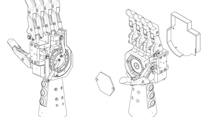
The selected thumb mechanism is combined with the fingers mechanism to become the hand mechanism that is connected to all fingers and thumb as in Fig. 13. The coupler path of this mechanism could provide different thumb motions when moved along different paths with each actuated direction.
For precision grip, the mechanism is actuated to the clockwise direction. Both sets of mechanisms then move fingers and thumb linkages toward the F1 and T1 positions simultaneously, in which the index, middle and thumb tips would touch each other, as in Fig. 14.

Figure 13. Hand mechanism at open hand position. Actuator position is between precision grip and power grip.
For a power grip, the mechanism is actuated to the opposite direction of precision grip (counter-clockwise). The fingers mechanism motion is identical to precision grip, whereas the thumb mechanism motion is different because the coupler point is moved along a different path with longer distance, thus causing delayed motion to thumb closure and allowing fingers to flex in first.

Figure 14. Hand mechanism when performing precision grip. Fingers and thumb flex simultaneously to touch each other’s tips.
Fingers prismatic joint is moved toward the F2 position, then the thumb prismatic joint is moved toward the T2 position in which the thumb tip would touch with the back of the index and middle fingers, as in Fig. 15.

Figure 15. Hand mechanism when performing power grip. Thumb mechanism flexion is delayed due to longer travel distance of coupler path; fingers flex in first then followed by thumb flexion touching with the back of the index & middle fingers to provide stability.
References
Describes the design of the prosthesis, mechanism synthesis, and achieved performance.
Recommended Specs

Continue Reading

In this episode, we discuss how MIT researchers are making great strides in developing better robotic hands by focusing on an often overlooked component: the palm.

14 minutes read
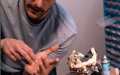
Clone Robotics’ humanoid hand uses hydraulics to mimic complex human hand function.

The heart of the new soft robot is a 'hysteretic valve', as the researchers call their invention in a publication in the journal Matter.