Surface Finish Symbols: How to Read a Drawing Callout
Surface finish symbols express a parameter, a limit, a process, and a lay direction in a callout the size of a check mark.

08 Oct, 2026. 9 minutes read
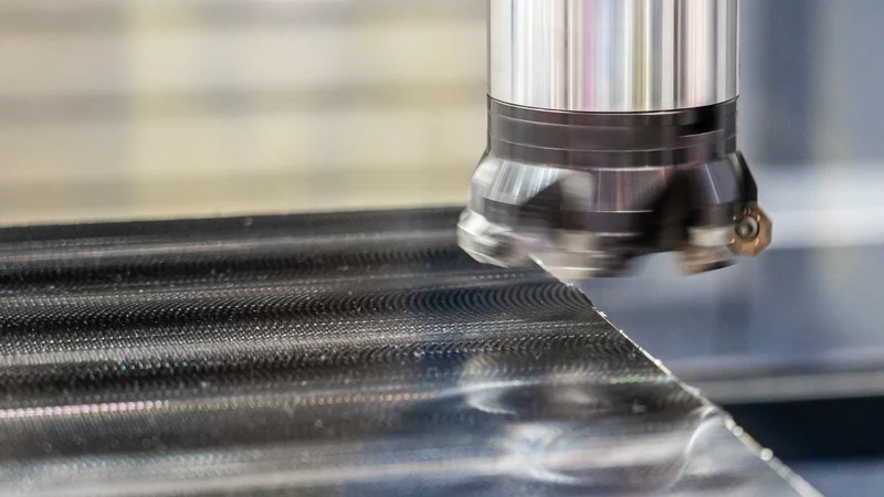
Precise surface finishing requires precise notation
Key Takeaways
The surface texture symbol has three forms: plain means any process is permitted, a bar across the “V” means material shall be removed, a circle means material removal is not permitted.[1]
ISO 1302:2002 has been withdrawn, and ISO 21920-1:2021 is its replacement.[1][2]
The current symbol carries a bar above it. ISO 21920-1 added that bar specifically to distinguish its symbols from the ISO 1302 ones, so the bar tells you which rulebook applies.[1]
Newer and older drawings place important information in differing locations around the symbol.
Introduction
A surface finish symbol or surface roughness symbol tells the machinist which process is allowed, how rough the surface may be, which way the tool marks should run, and how much stock to leave for a later operation.
This guide covers the symbol seen on engineering drawings: the current ISO form, the ISO 1302 form that a large share of drawings in service were drawn to, older styles you will find on legacy drawings, and the North American ASME form. It focuses on reading and writing the callout. For the Ra numbers themselves, see the companion surface roughness chart, and for how the surface roughness values are captured, see the measuring surface roughness guide.
The Surface Texture Symbol and Its Three Forms
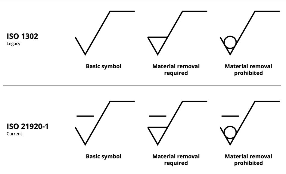
The basic graphical symbol is two straight lines of unequal length, inclined at approximately 60° to the line representing the surface being specified.[1] It looks like an elongated check mark or square-root sign.
Adding a bar across the “V” of the symbol means material removal is required; adding a circle means material removal is not permitted.[1] Those two marks change what the shop is allowed to do.
Form | Meaning | Text abbreviation | What the shop may do |
Plain symbol | Any manufacturing process permitted | APA (any process allowed) | Machining or non-machining, the shop chooses |
Symbol with a bar across the V | Material shall be removed | MRR (material removal required) | Must machine, grind, hone or otherwise cut the surface |
Symbol with a circle in the V | Material removal is not permitted | NMR (no material removed) | Must leave the as-formed surface: cast, forged, rolled, injection molded |
The three-letter abbreviations exist for written text such as reports and contracts, where you cannot draw the symbol.[1]
To carry any complementary requirement, a horizontal line is added to the longer arm of the symbol.[1] A circle over the kink of the complete symbol (where the top right of the “V” meets the horizontal line) means the requirement applies to all surfaces around the workpiece outline shown on that view.[2] But this is no longer used in the latest ISO standard.[1]
A surface texture requirement is indicated only once for a given surface, and where possible on the same view that carries the size or location dimensions and their tolerances. The symbol must touch the surface or connect to it by a reference line and leader terminating in an arrowhead, pointing at the surface from outside the material.[1]
What Each Value Around the Symbol Means
This is the part engineers get wrong most often, because the values included on the surface finish callout (and their position) depend on the surface finish standard being used.
ISO 21920-1
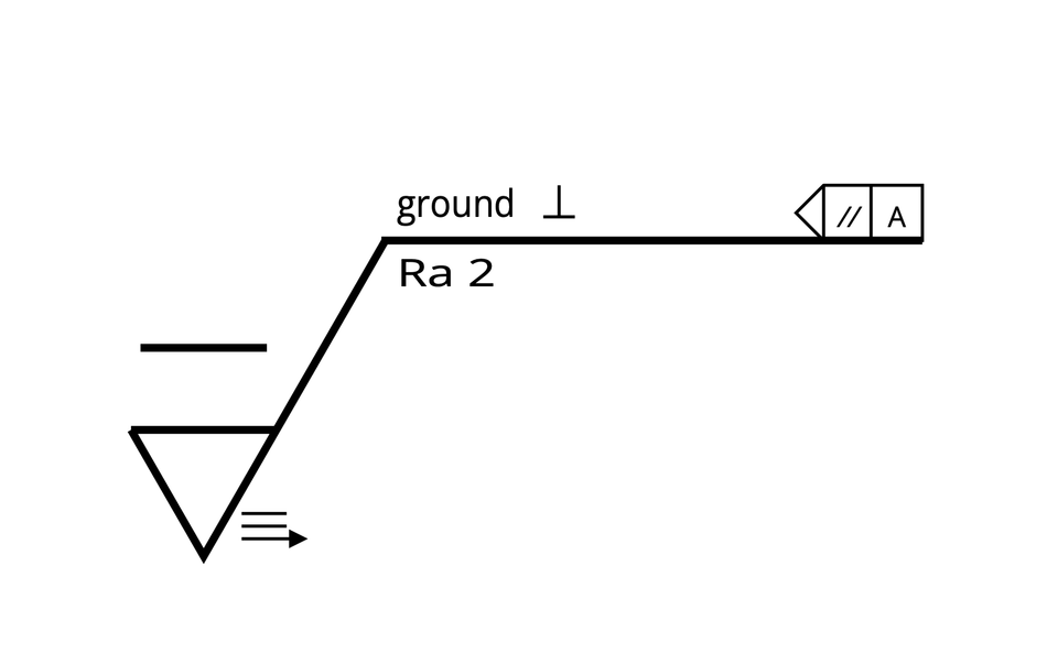
The current ISO standard for surface finish specifications requires, at a minimum, the graphical symbol described above in one of its three forms, a symbol to indicate the parameter being used (Ra, Rz, etc.), and a numerical value.[1] Everything else is optional and defaults if omitted.
Information on the callout can include:[1]
Manufacturing process (above the horizontal line, to the left)
Lay (above the horizontal line, to the right)
The R-parameter and its specified value (below the horizontal line)
Various optional modifiers relating to the R-parameter (below the horizontal line)
Profile direction relative to surface lay (to the right of the “V” of the symbol)
For an evaluation-length R-parameter such as Ra, the (optional) elements must be placed in a specific syntactical order, namely: tolerance type, parameter symbol, tolerance limit value, tolerance acceptance rule, S-filter type and nesting index, L-filter type and nesting index, evaluation length, F-operator association method and nesting index, method of profile extraction, an other-requirements placeholder, manufacturing process, surface lay and direction of lay, and profile direction relative to the lay.[1]
A minimal indication is just the symbol, the parameter and the limit, and ISO notes that the complete indication “might be rarely used in practice.”[1] Parameters with defined defaults include Rz, Ra, Rp, Rv, Rq, Rmax, Rt, and Pt.[1]
Recommended reading: Surface Finish: Parameters, Standards, and How to Specify It
ISO 1302
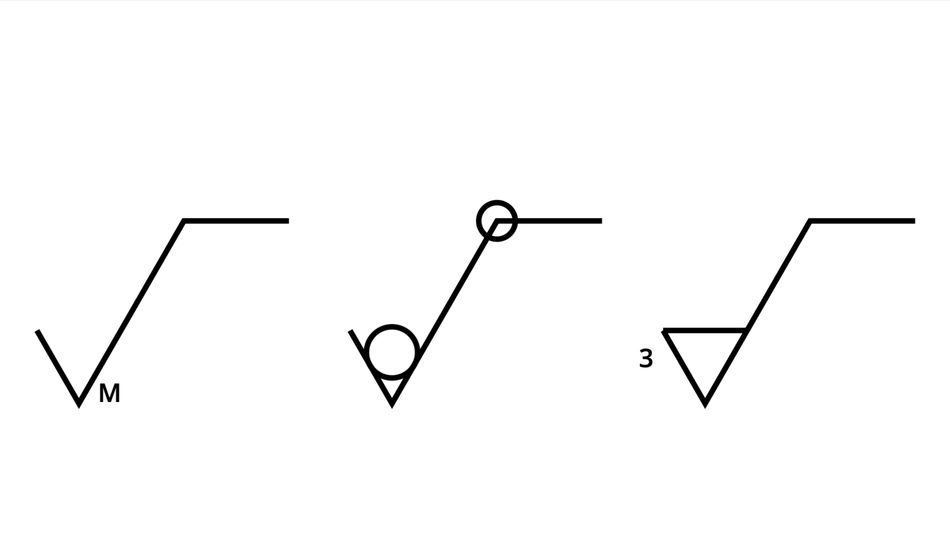
Under ISO 1302:2002, the final version of the old standard, some values are found in different places. And since ISO 1302 was only replaced in 2021, drawings with ISO 1302 are still very common.
As with the current ISO standard, the R-parameter and its value is found under the horizontal line and the manufacturing process (if specified) is found above the line.[2]
But differences include:[2]
Lay (to the right of the “V”)
Machining allowance (to the left of the “V”)
Circle symbol indicating that the requirement applies to all surfaces around the workpiece outline shown on that view (where the “V” meets the horizontal line)
Historical ISO standards
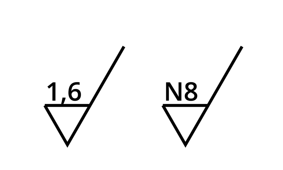
Surface finishing as a serious engineering practice has existed for almost a century, and common surface symbols entered usage in the 1960s.[3]
Drawings outlive standards. On older drawings, the roughness is often given as a roughness grade number rather than an explicit Ra value, a convention that goes back to the 1971 ISO recommendation and its table of grade numbers.[4] Those grade numbers are mapped to Ra values in our surface roughness chart.
The 1971 recommendation that preceded ISO 1302 already used the same basic check mark, the same bar for material removal required and the same circle for material removal not permitted.[4]
However, between 1971 and 1992, values were found in different locations around the symbol,[2] notably:
The R-parameter and its specified value (directly above the “V”, defined as “position x” in old standards)
Recommended reading: Surface Finish Chart: Ra, Rq, and N-Grade Conversions
ASME Y14.36
North American engineering drawings follow the American Society of Mechanical Engineers rather than ISO. The relevant standard is ASME Y14.36M, currently in its 2018 edition, reaffirmed in 2024.[5]
Differences between the ISO and ASME standards are fairly minor. Callouts following ASME Y14.36 closely resemble those following the withdrawn ISO 1302.
Notable placements include:[5]
Lay (to the right of the “V”)
All-around modifier: Circle symbol indicating that the requirement applies to all surfaces around the workpiece outline shown on that view (where the “V” meets the horizontal line)
All-over modifier: Variant of the above, two concentric circles indicating that the requirement applies to all surfaces of the part (where the “V” meets the horizontal line)
American drawings also commonly work in microinches where ISO drawings work in micrometers; ASME allows either.[5]
Lay Direction Symbols in Full
Lay is the predominant direction of the surface pattern, ordinarily determined by the production method used.[6] It is the direction of the tool marks, and it is specified separately from any roughness value because two surfaces with an identical Ra value can behave completely differently depending on which way the grooves run.
That matters most on seals, bearings, and sliding contacts, where the grooves either guide fluid along the joint or across it. On a honed cylinder bore, the crosshatch pattern is specified as lay because the direction of the marks does work that no single roughness value can describe.
ISO and ASME standards use equivalent lay symbols. However, the current ISO standard defines the first three according to an intersection plane indicator and datum feature indicator in the top right of the callout, whereas older ISO standards and ASME define them by the plane of projection.[1][5]
The mapping below is taken directly from the current ISO standard.[1]
Symbol | Meaning | Typical process |
= | Parallel to direction | Shaping, planing, some milling |
⊥ | Perpendicular to direction | Shaping, planing across the view |
X | Crossed in two oblique directions relative to the direction | Honing, crosshatched bores |
M | Multidirectional | Lapping, blasting, polishing, superfinishing |
C | Approximately circular relative to the centre of the surface to which the symbol applies | Facing and turning on a lathe |
R | Approximately radial relative to the centre of the surface to which the symbol applies | Some grinding and facing operations |
P | Lay is particulate, non-directional, or protuberant | Powder coating, electro-deposited and sprayed finishes |
ISO Standard Changes
ISO 1302:2002 has been withdrawn and replaced by ISO 21920-1, whose first edition is dated 2021-12.[1]
The new standard sits in a three-part series: Part 1 covers indication on drawings, Part 2 covers terms, definitions, and parameters, and Part 3 covers specification operators.[1] Note that ISO 21920-1 is already at stage 90.92, “International Standard to be revised.”[1]
Some changes from the old to the new ISO standard have already been discussed, such as the removal of the machining allowance value and the all-surfaces application symbol. Below are three other notable changes in the new standard:
1. Bar above symbol
ISO 21920-1’s graphical symbols carry a horizontal bar above the main symbol: “The bar above the symbol is to distinguish this symbol from the ones used in ISO 1302 and those used for indication of areal surface texture specifications.”[1]
The bar is a version stamp. So if the symbol has it, you can read the callout under ISO 21920-1 rules; if it does not, it should be read under ISO 1302 rules or whatever other standard has been specified.
The three forms themselves are unchanged in meaning: any manufacturing process permitted, material shall be removed, material removal is not permitted.[1]
2. New default acceptance rule
Under ISO 1302, a limit with no rule stated meant the 16% rule, the ISO 4288 default, which allows at most 16% of measured values to violate the limit.[1][2]
Under ISO 21920-1, the default is the maximum tolerance acceptance rule, which “does not allow any measured value to exceed the tolerance limit” and which is “the default case and valid with or without indication of the Tmax symbol.”[1]
The same drawing value, unchanged, is harder to pass under the new default. A third option now exists too: the median rule, where the median of all measured values must meet the limit, using at least three measurements.[1]
3. Element set syntax expansion
ISO 21920-1 replaced the “a-to-e” scheme (where five letters were used to specify where values should appear on a callout) with a longer, ordered specification string.
For an evaluation-length R-parameter such as Ra, the elements run: tolerance type, parameter symbol, tolerance limit value, tolerance acceptance rule, S-filter type and nesting index, L-filter type and nesting index, evaluation length, F-operator association method and nesting index, method of profile extraction, an other-requirements placeholder, manufacturing process, surface lay and direction of lay, and profile direction relative to the lay.[1]
Conclusion
Surface finish symbols are a compact, positional language, and almost all the difficulty is in the positions rather than the values. Learn the three symbol forms, learn what sits at each position, and learn the seven lay symbols, and you can read any surface texture symbol you meet.
Remember that ISO 1302 is withdrawn, ISO 21920-1:2021 replaced it, and the replacement changed both the appearance of the symbol, by adding a bar above it, and the meaning of a bare limit, by making the maximum rule the default.[1][2] However, drawings drawn to ISO 1302 will stay in service for years yet, so you need to read both schemes, and the bar is how you tell them apart.
When you write a callout, specify the parameter, the limit, the cutoff, and the lay where it matters, and leave everything else to defaults. When you read one, check the bar first.
Frequently Asked Questions
What are surface finish symbols?
They are standardized graphical symbols used on technical drawings to specify the required texture of a surface profile.
What does a bar or a circle on the symbol mean?
A bar added to the basic symbol means material shall be removed, so the surface must be machined. A circle means material removal is not permitted, so the surface must be left as cast, forged, rolled or molded. A plain symbol means any manufacturing process is permitted.
What does 32 surface finish mean?
On a North American drawing a bare 32 surface geometry is conventionally read as Ra 32 µin, because American drawings commonly work in microinches.
How do you specify surface finish on a drawing?
Draw the appropriate symbol form, add the horizontal extension line, then place the parameter designation and its limit value below the extension line.
Is ISO 1302 still current?
No. ISO lists ISO 1302:2002 as withdrawn at stage 95.99 and names ISO 21920-1:2021 as its replacement.[1] You still need to be able to read ISO 1302 callouts, because many drawings in service predate the change and will not be redrawn.
What is the difference between ISO and ASME surface finish symbols?
The symbol shape is shared, but value positions and units differ, as described above.
What do the lay symbols mean?
There are seven: = for parallel, ⊥ for perpendicular, X for crossed, M for multi-directional, C for approximately circular, R for approximately radial, and P for particulate, non-directional or protuberant lay.
References
[1] International Organization for Standardization. ISO 21920-1:2021. Geometrical product specifications (GPS) — Surface texture: Profile — Part 1: Indication of surface texture. Geneva: ISO; 2021.
[2] International Organization for Standardization. ISO 1302:2002. Geometrical Product Specifications (GPS) — Indication of surface texture in technical product documentation. Geneva: ISO; 2002. Withdrawn 2021.
[3] Nugent P. 50 Years of Quality: A Superficial History of Surface Finish [Internet]. Quality Magazine. 2011 Apr 1 [cited 2026 Oct 7].
[4] International Organization for Standardization. ISO/R 1302:1971. Technical drawings — Method of indicating surface texture on drawings. Geneva: ISO; 1971. Withdrawn 1976.
[5] American Society of Mechanical Engineers. ASME Y14.36-2018 (R2024). Surface Texture Symbols. New York: ASME; 2018.
[6] American Society of Mechanical Engineers. ASME B46.1-2019. Surface Texture (Surface Roughness, Waviness, and Lay). New York: ASME; 2019.