Sheet Metal Manufacturing: Innovating Industrial Techniques
This sheet metal manufacturing guide for digital design engineers, hardware professionals, and electronics students covers theory, design, and equipment.

Last updated on 31 Oct, 2025. 11 minutes read
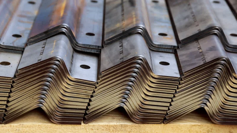
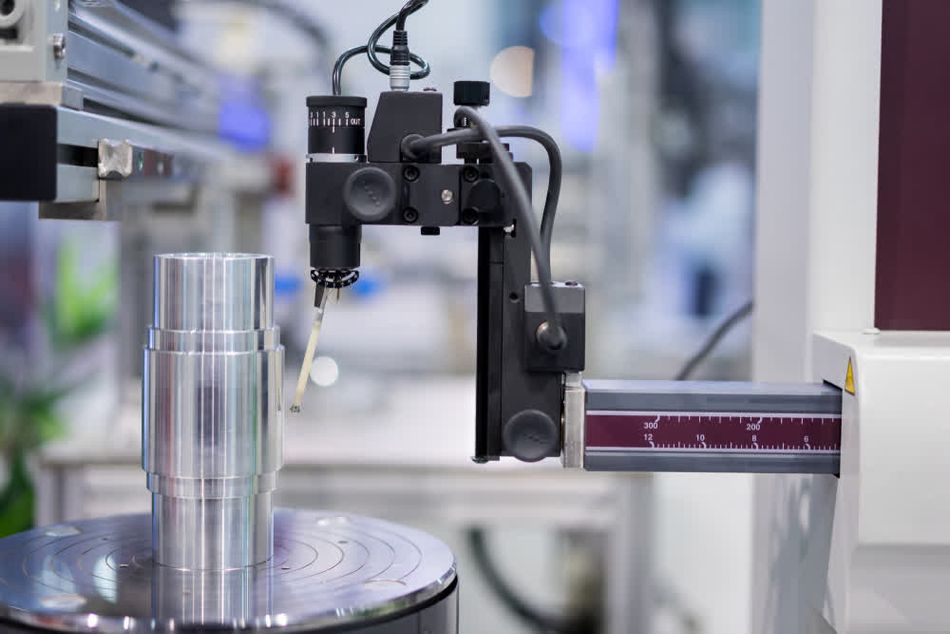
Sheet metal manufacturing encompasses several unique processes
Sheet metal is the quiet backbone of modern engineering. From electronics enclosures to HVAC ducts and lightweight automotive brackets, it shapes the products we rely on daily. Its versatility comes from a range of materials and thicknesses, combined with processes that can cut, bend, stretch, and join with precision.
For engineers, mastering sheet metal is about more than theory. It’s about balancing calculations with practical know-how, understanding tolerances, and leveraging processes to achieve both performance and manufacturability. Each design choice has implications for strength, cost, and long-term reliability.
This guide delivers a focused, engineer-oriented perspective on sheet metal manufacturing. It covers fundamental concepts, dives into forming and cutting techniques, and explores design for manufacturability, digital simulation, and more. The goal: to give readers the tools to design robust, cost-effective sheet metal components for today’s products.
Fundamentals of Sheet Metal
Sheet metal is one of the most versatile material forms in manufacturing, being found in everything from consumer electronics to vehicles and architectural structures. The advantages of sheet metal lie in its balance of strength, adaptability, and cost efficiency: a single piece of sheet metal can be cut, bent, or formed into a wide variety of complex shapes without losing durability. Because of this versatility, it supports countless applications, from enclosures and brackets to structural frames and cladding, and underpins all modern sheet metal fabrication processes.
Sheet metal refers to metal stock that is thin enough to be bent or shaped, yet thick enough to provide meaningful structural strength. Its thickness is typically specified by gauge.
In general, sheet metal falls in the range of 0.5 mm to 6 mm; thicker stock is usually classified as plate.[1] Designers should select thickness based on functionality, weight targets, and the fabrication techniques available. Thinner sheets may require stiffening features such as flanges or ribs to ensure rigidity, while thicker sheets demand greater force during bending sheet metal operations and can limit the minimum achievable bend radius.
Materials for Sheet Metal Manufacturing
Sheet metal can be produced from virtually any metallic material, including:
Material | Key Characteristics | Common Uses | Common Grades |
Mild steel | Affordable, strong, easy to form and weld | Enclosures, frames, carriers, non-visible automotive parts | ASTM A36, EN 1.0038, S275JR |
Stainless steel | Excellent corrosion resistance, hygienic surface, good weldability | Medical equipment, food processing systems, chemical plants, maritime components | 304, 316, 430 |
Aluminium | Lightweight, corrosion-resistant, high strength-to-weight ratio, good machinability | Aerospace structures, vehicle panels, electronic housings, façade cladding | 5052, 6061, 7075 |
Copper & copper alloys | Superior electrical and thermal conductivity, high ductility, attractive appearance | Busbars, heat exchangers, plumbing, decorative architectural features | C11000 (pure Cu), C26000 (brass), C93200 (bronze) |
Advanced materials | High strength, durability, excellent corrosion resistance, often low density | Aerospace, high-performance automotive, defense, marine, medical implants, sports equipment | Ti-6Al-4V, Al-Li 8090, S355JR |
Forming Sheet Metal
Sheet metal forming alters the geometry of a sheet without removing material. When the applied force exceeds the yield strength, the sheet undergoes plastic deformation rather than fracture. During bending, outer fibres stretch, inner fibres compress, and a neutral axis remains unchanged in length. Accurately locating this neutral axis—and applying the K-factor (the ratio of its position relative to sheet thickness)—is required for calculating bend allowances and deductions.[2] In practice, these allowances may be provided by the material supplier or calculated automatically using software.
Bending
Bending uses a punch and die to impose a controlled angle in the sheet. Key parameters include the bend line, mold line distance, flange length, bend radius, and bend angle. Engineers must account for material stretching through bend allowance and bend deduction when developing flat patterns. Common bending methods include:
V-bending: the punch drives the sheet into a V-shaped die. Air bending occurs when the punch does not bottom out, while bottoming forces the sheet to conform fully to the die cavity for greater accuracy.
Wipe bending: also called edge bending, where a wipe die holds the sheet and forms a flange along its edge.
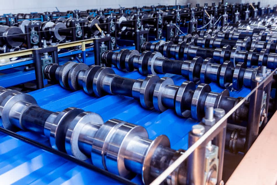
Roll forming
Roll forming progressively bends sheet metal through a series of roll stations. This enables production of long parts with constant or gradually changing cross sections, achieving tight tolerances. The process is widely used for tracks, shelving, structural profiles, and panel systems where repeatability and length are important.
Spinning
Metal spinning produces axisymmetric hollow parts by pressing a rotating blank against a mandrel with a roller. In conventional spinning, the diameter decreases while thickness remains constant, whereas shear spinning reduces wall thickness while maintaining diameter. This method is commonly used for cookware, hubcaps, satellite dishes, and aerospace nose cones.
Deep drawing
Deep drawing forms a flat blank into a die cavity using a punch, producing a depth greater than half the part’s diameter. This technique is essential for automotive body panels, fuel tanks, sinks, and cans. Multiple drawing stages are often required to prevent tearing, and blank holders are used to carefully control metal flow.
Stretch forming
Stretch forming combines stretching and bending by pulling a sheet over a form block with hydraulic or pneumatic jaws. It produces smooth, contoured parts with high dimensional accuracy. Applications include aircraft fuselage panels, wing skins, and large automotive or architectural components. Materials such as aluminum, titanium, and mild steel are often selected for their ductility.
Recommended reading: Metal 3D Printing: A Comprehensive Guide for Engineers and Students
Cutting Sheet Metal
Sheet metal cutting relies on shear forces to separate material along a defined line. When the applied shear stress exceeds the ultimate shear strength of the metal, the sheet fractures and separates.[3] The quality of the cut depends on clearance between tool edges, material properties, and the type of process used.
Shearing
Shearing makes straight cuts, either parallel or angled to an existing edge, and is often used to cut stock to size before forming. A squaring or power shear clamps the sheet and drives a blade across it with a controlled clearance—typically a small percentage of the sheet thickness. Shearing can handle thin foils through moderately thick plates, offering good productivity and accuracy for preparing blanks.
Blanking and Fine Blanking
Blanking uses a punch and die to cut out a two-dimensional shape, with the punched slug becoming the finished part. It is suited for high-speed production, though secondary finishing may be required to remove burrs. Fine blanking is a precision variant that applies additional holding and counterpressing forces, creating smooth, accurate edges with minimal secondary work. It is commonly used for high-volume parts requiring tight tolerances, such as gears, levers, and small electronic components.
Punching
Punching follows the same principle as blanking, but here the slug is discarded and the remaining sheet becomes the workpiece. This process is used to create holes, slots, or complex cutouts. Modern CNC punching presses can perform hundreds of strokes per minute and often use turrets to switch between multiple punch shapes during a single program.
Stamping
Stamping combines cutting and forming operations in a single press stroke, making it one of the most efficient processes for high-volume production. Operations such as blanking, bending, punching, and embossing can be performed together, enabling rapid manufacture of automotive panels, appliance parts, and consumer goods.
Coining
Coining is an intensive form of stamping that uses exceptionally high pressures to force the punch deep into the material. This allows the formation of fine details, small radii, and sharp edges with excellent repeatability. Originally developed for minting coins, the process is now used to produce high-definition features in precision components.
Design for Manufacturability (DFM) and Practical Guidelines
Good sheet metal design balances performance, visual appeal, and production efficiency. Overly complex designs or excessively tight specifications can increase tooling costs and risk defects, while well-considered features can simplify fabrication, reduce waste, and improve assembly fit. The goal is to design parts that are both practical to manufacture and reliable in service.
Factors That Influence Manufacturability
Several factors determine how closely a part can be fabricated to its intended design. Material choice plays a central role: thin aluminum sheets may deform more easily than thicker steel, while hot-rolled steels often carry more dimensional variation than cold-rolled grades. Process complexity is another factor, as each cut, bend, or forming step introduces incremental variation that accumulates across the part. Equipment precision also matters—modern CNC press brakes can consistently hold tight angles, but simpler mechanical tools may not.
Bend and Feature Design
Well-planned bends are required to ensure part strength and accuracy. Avoid placing holes or slots too close to bends, since this can cause distortion; a safe rule is to provide several times the material thickness as clearance. Flanges should be kept long enough to allow proper gripping and forming, and offset bends (Z-shapes) should maintain adequate spacing between planes to prevent interference. Consistent bend radii not only reduce cracking risk but also minimize tool changes, making production more efficient.
When designing holes, slots, or cutouts, ensure they are proportioned to the sheet thickness and maintain sufficient distance from edges or bends. Using standard hole sizes also reduces tool wear and improves interchangeability. Edges may be curled or hemmed for strength and safety; open or teardrop hems are often favored over flat hems to avoid trapped stresses.
Reducing Complexity in Design
Simplifying part geometry reduces the need for multiple reorientations during forming and speeds up production. Using standard hardware such as threaded inserts or rivets typically saves time compared to custom weldments. Where welding is required, minimizing the number of seams and ensuring proper joint access lowers labor effort and improves consistency.
Finishing and Assembly Considerations
Surface finishes improve both appearance and performance. Powder coating provides durable protection and masks minor forming marks, while plating or anodizing can enhance corrosion resistance. In corrosive environments, treatments such as zinc or chromate coatings are common. For assembly, both welding (MIG, TIG, spot) and mechanical fastening (rivets, PEM inserts, bolts) are widely used.[4] Designers should leave enough clearance around bends and edges for these operations, or add relief features to prevent deformation during fastening.
Sheet Metal DFM Checklist
Material choice: Select grade and thickness suited to strength, weight, and forming capability.
Bend design: Use consistent radii, keep bends away from holes/edges, and allow adequate flange length.
Feature spacing: Maintain clearances between cutouts, bends, and edges to prevent distortion.
Complexity: Minimize unnecessary bends or reorientations; use standard hardware where possible.
Edges: Use curls or hems to strengthen and remove sharpness; prefer open or teardrop hems over flat hems.
Finishing: Choose surface treatments (powder coat, anodize, plating) early to account for masking and tolerances.
Assembly: Provide clearance for fasteners and welding tools; use reliefs near bends to avoid deformation.
Digital Design and Simulation
Producing high-quality sheet metal parts means anticipating and preventing defects before they reach the shop floor. Virtual die try-outs powered by finite element analysis (FEA) let engineers simulate forming operations and evaluate risks such as springback, wrinkles, or thinning long before tooling is cut.[5] By adjusting parameters like material grade, die geometry, press speed, or lubrication in the digital environment, designers can refine their approach without incurring the cost and delay of multiple physical trials.
Benefits of Simulation
Simulation offers more than defect avoidance. It provides a structured way to optimize performance, appearance, and cost:
Material formability analysis – Map stresses, strains, and required press forces across alloys and thicknesses.
Springback control – Anticipate elastic recovery and adjust tool offsets or process settings to meet dimensional targets.
Cosmetic quality prediction – Detect thinning, wrinkling, or surface issues early to ensure parts meet aesthetic requirements.
Cost reduction – Limit the need for physical prototypes, shorten development cycles, and optimize tooling designs.
Integration with CAD/CAE Workflows
Modern CAD platforms such as SolidWorks, CATIA, and Inventor include sheet metal modules that convert 3D models into flat patterns while automatically applying bend allowances and springback factors. When paired with CAE tools like Ansys Forming, PAM-STAMP, or AutoForm, engineers can rapidly iterate between design and simulation.
Additional benefits of CAD/CAE integration include:
Embedding DFM rules in CAD libraries to warn when features are too close to bends or thickness limits.
Enabling multi-physics evaluation early in design. For instance, an electronics enclosure may need:
Electromagnetic shielding
Heat dissipation through ventilation slots
Structural rigidity for mechanical stability
Recommended reading: CNC Programming: Mastering Precision and Efficiency in Engineering
Sheet Metal Manufacturing Equipment
Equipment Type | Function | Common Variants | Typical Applications |
Press Brakes | Bend flat sheet into the desired shape through controlled force | Hydraulic and servo-electric brakes with computer numerical control (CNC machining) | Enclosures, brackets, structural frames, precision bends |
Shears / Guillotines | Straight-line cutting of raw materials prior to forming | Mechanical or hydraulic guillotines | Cutting large sheets to size for further manufacturing processes |
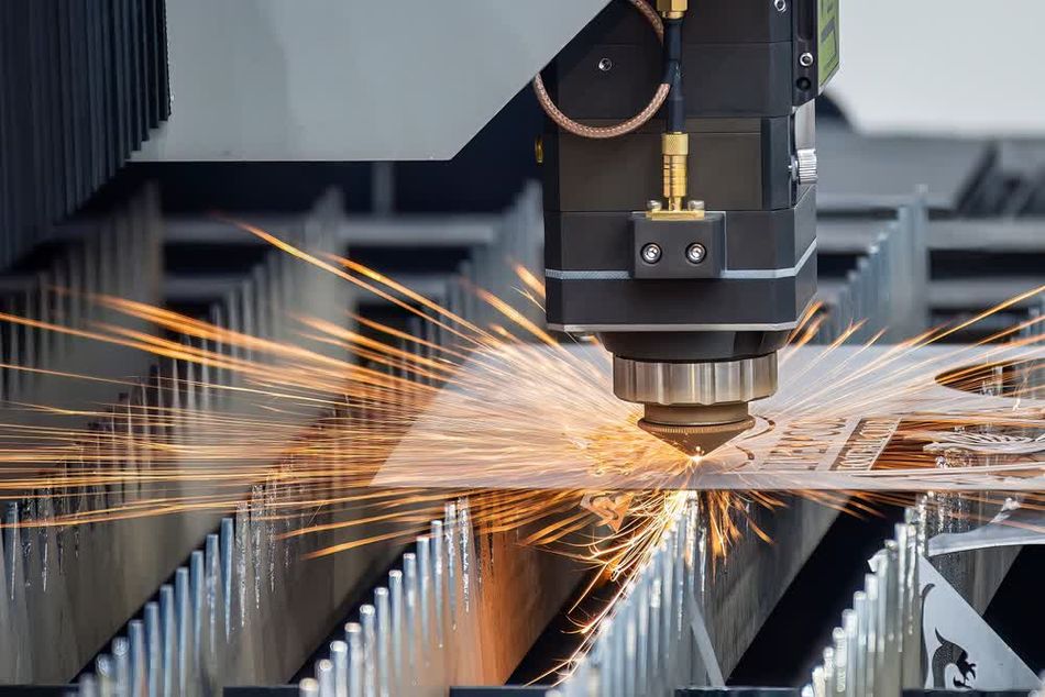
Laser Cutters | Use a concentrated laser beam to cut flat sheet metal with high precision | Fiber and CO₂laser cutter systems | Electronics housings, aerospace panels, decorative panels, complex geometries |
Plasma Cutters | Jet of ionized gas cuts conductive types of metal at high temperatures | CNC plasma cutting tables, handheld torches | Structural beams, automotive frames, shipbuilding components |
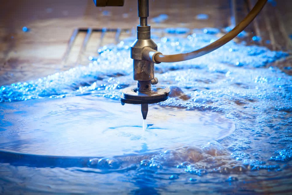
Water Jet Cutters | High-pressure water mixed with abrasive particles cuts without heat distortion | Pure water jets (soft materials), abrasive jets (hard metals) | Thick aluminum, stainless steel, composites, aerospace and architectural parts |
Punching Machines | Remove slugs to create holes, slots, or cutouts in sheet metal | CNC turret presses, single-station punch presses | Perforated panels, ventilation slots, fast, repeatable cut patterns |
Stamping Presses | Apply one stroke to cut and form raw materials into near-finished parts | Progressive die presses, mechanical and hydraulic presses | Automotive body panels, appliance housings, high-volume consumer goods |
Roll Forming Machines | Continuous forming processes bend sheet along rollers | Tandem or continuous roll formers | Roof panels, long profiles, construction framing |
Spinning Machines | Rotational forming of axisymmetric parts using a mandrel and roller | Manual spinning lathes, CNC spinning | Aerospace nose cones, cookware, decorative lighting fixtures |
Welding Equipment | Joins sheet metal with fusion at high temperatures | MIG, TIG, resistance spot welders | Automotive frames, industrial enclosures, custom structures |
Fastener Installation Tools | Attach hardware mechanically instead of welding | PEM insertion presses, riveting machines | Cabinets, electronics housings, precision sheet metal fabrication assemblies |
Inspection Systems | Ensure dimensional accuracy and surface quality of the final product | CMMs, laser scanners, digital calipers | Quality checks, detection of burrs or oxide build-up, sheet metal fabrication services |
Surface Finishing Equipment | Protect and improve appearance of types of metal components | Powder coating lines, anodizing tanks, plating baths | Corrosion resistance, cosmetic finishes, high-quality exterior parts |
Conclusion
Sheet metal manufacturing brings together materials science, mechanics, and precision engineering in a way few other processes do. Success depends on selecting suitable materials, understanding forming behaviour, and applying design-for-manufacturability principles from the start. Techniques such as bending, roll forming, spinning, deep drawing, shearing, and punching provide engineers with a flexible toolkit for shaping metal into reliable components.
Today’s advances in simulation, CNC-controlled presses, and integrated CAD/CAE workflows make it possible to achieve both accuracy and efficiency. As automation and sustainability gain traction, engineers who adopt digital tools, collaborative design practices, and thoughtful material choices will be best equipped to deliver innovative and manufacturable sheet metal products.
Frequently Asked Questions (FAQ)
What is the difference between sheet metal and plate?
Sheet metal is typically 0.5–6 mm thick; anything thicker is classified as plate. Plates require heavier machinery for forming and are often cut by plasma or oxyfuel rather than sheared or punched.
How can I reduce springback in bending?
Springback—elastic recovery after bending—can be reduced by choosing ductile materials, using larger bend radii, bottoming instead of air bending, applying over-bending, and adjusting tooling. Simulation tools can also predict and compensate for springback.
Why are hole diameters often specified as at least the sheet thickness?
Holes smaller than the sheet thickness can cause burrs or distortion. A safe guideline is to keep hole diameters equal to or greater than material thickness (minimum 1 mm) and space them at least 2× thickness from edges.
When should I use fine blanking instead of conventional blanking?
Fine blanking produces parts with smooth edges, flatness, and tight tolerances by applying three forces instead of fracturing the sheet. It is best for high-volume production where higher tooling cost is offset by eliminating secondary finishing.
How do I select the right sheet metal material?
Match material to requirements: steel for strength and cost, stainless for corrosion resistance and aesthetics, aluminium for low weight and conductivity, copper for electrical use, and high-strength alloys or titanium where performance outweighs cost.
How much does sheet metal fabrication cost?
Costs vary by material type, thickness, process choice, and order volume. Laser cutting and CNC bending add precision but increase setup cost, while stamping is economical for high-volume runs.
References
[1] Metal Supermarkets. The difference between metal sheet and plate [Internet]. March 9, 2022 [cited 2025 Oct 27]. Available from: https://www.metalsupermarkets.com/the-difference-between-metal-sheet-and-plate/
[2] ASM International. ASM handbook. Volume 14B, Metalworking: Sheet forming. Materials Park (OH): ASM International; 2006. Available from: https://www.asminternational.org/results/-/journal_content/56/05120G/PUBLICATION
[3] Roth CC, Mohr D. Determining the strain to fracture for simple shear for a wide range of sheet metals. International Journal of Mechanical Sciences. 2018 Dec 1;149:224-40. Available from: https://doi.org/10.1016/j.ijmecsci.2018.10.007
[4] Barr E. Professional sheet metal fabrication. Motorbooks; 2013 Apr 15. Available from: https://books.google.ca/books?hl=en&lr=&id=flD0AwAAQBAJ
[5] AHSS Insights. Simulation overview: Sheet-metal forming simulation [Internet]. AHSS Guidelines. [cited 2025 Oct 27]. Available from: https://ahssinsights.org/forming/simulation/simulation-overview/
in this article
1. Fundamentals of Sheet Metal2. Materials for Sheet Metal Manufacturing3. Forming Sheet Metal4. Cutting Sheet Metal5. Design for Manufacturability (DFM) and Practical Guidelines6. Digital Design and Simulation7. Sheet Metal Manufacturing Equipment8. Conclusion9. Frequently Asked Questions (FAQ)10. References