Guide to PCB Mounting: Techniques, Tips, and Best Practices
PCB mounting is critical for ensuring the lifetime and dependability of electronic products, including careful component selection and location, adherence to industry standards, and the use of high-quality materials and assembly procedures. This post will go over PCB mounting techniques, tips, and best practices and expand on crucial aspects of printed circuit board mounting.

21 Apr, 2023. 16 minutes read
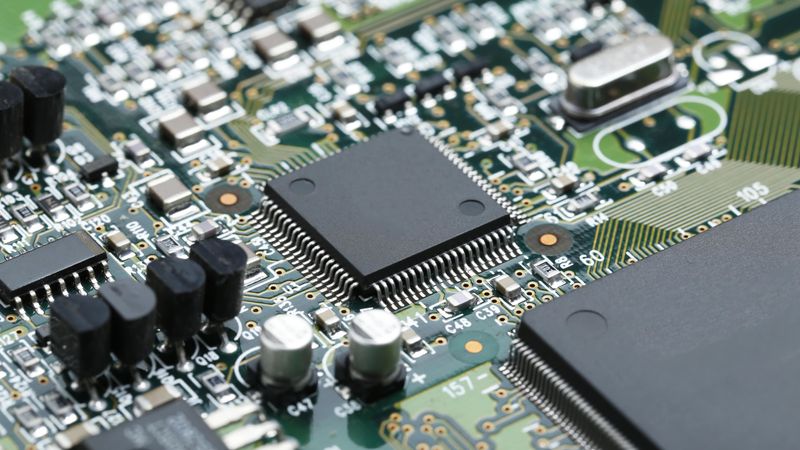
A Printed Circuit Board
Introduction
PCB mounting is an important aspect of electronics manufacturing and assembly, as it affects the performance and reliability of electronic devices. Understanding the best practices and techniques for PCB mounting has become increasingly important for industry professionals as electronic products become more complex. This comprehensive guide aims to provide an in-depth understanding of PCB mounting, including factors to consider before mounting, common mounting techniques, necessary tools and equipment, and best practices to ensure optimal performance. By the end of this article, you'll have a solid understanding of PCB mounting principles and be well-prepared to tackle your next project with confidence. So, let's dive in and explore the fascinating world of PCB mounting.
What is PCB Mounting?
PCB mounting is the process of attaching electronic components to a printed circuit board to create a functional electronic assembly. This procedure employs a variety of techniques, tools, and equipment to ensure secure connections between the components and the board, allowing electrical signals to flow efficiently through the circuit. The goal of PCB mounting is to provide a stable and reliable platform for electronic components, allowing them to function properly within the constraints of the device's design. PCB standoffs and spacers aid in the preservation of space and component positioning on your PCB.
There are several types of PCBs that can be mounted, including single-sided, double-sided, and multilayer boards, each with unique characteristics that influence the mounting technique used and the overall assembly process. In this guide, we will look at the factors to consider before mounting a PCB, as well as the common techniques and best practices for a successful assembly.
PCB mountingis an important stage in electronic assembly, particularly when working with high-power and novel products. When putting components on a printed circuit board (PCB), variables such as part number, RoHS compliance, and optimum positioning must be considered.
Diodes, capacitors, fuses, and resistors are some of the most common components that must be mounted on a PCB. These components are critical in regulating and controlling electrical signals and must be firmly placed to ensure optimal operation.
There has been an increase in the need for new goods and modules in recent years, which necessitate specialised mounting techniques and considerations. High power modules, for example, frequently necessitate the use of specialised heat sinks and thermal management technologies to prevent overheating and assure reliable operation.
Recommended reading: Bare Board PCB: Everything You Need to Know
Factors to Consider Before Mounting a PCB
Prior to beginning the PCB mounting process, it is crucial to take into account a number of variables that may affect the choice of mounting method and the assembly's final outcome. These elements include the board's size and shape, the density of its components, and the needs for thermal management. Making informed decisions and avoiding potential problems during assembly are made possible by understanding how these factors affect the mounting process.
Board Size and Shape
The size and shape of a PCB are important considerations during the mounting process. Large or irregularly shaped boards require specialised equipment or mounting techniques to ensure proper assembly because they are more prone to flexing, warping, or slipping during mounting. Additional support may be required for large boards to avoid flexing or warping. Using support structures such as blocks or jigs to keep the board stable and level during assembly could be an example of this. To hold irregularly shaped boards securely during assembly, custom fixtures or clamps may be required. It is critical to carefully plan the mounting process and ensure that the technique chosen is compatible with the dimensions and design of the board. If the mounting method is not properly planned, it can lead to errors, waste, and even damage to the board or components.
Component Density
When planning the PCB mounting process, component density must be taken into account. The number of electronic components on a PCB in relation to its size can have a significant impact on the complexity of the mounting process.
High component density on a PCB can make mounting more difficult because it necessitates precise placement and soldering to avoid short circuits or other problems. More advanced mounting techniques, such as the use of automated pick-and-place machines or stencil-applied solder paste, may be required for a high-density board. These techniques take more time and require specialised equipment, raising the overall cost of PCB assembly.
Low component density, on the other hand, may allow for simpler mounting techniques and fewer potential complications. Depending on the complexity of the board's design, some low-density boards may still require precise placement and soldering.
It is critical to account for component density and choose a mounting technique that can accommodate the required level of precision and complexity when planning the PCB mounting process. Failure to consider component density and choose an appropriate mounting technique can result in short circuits, component damage, or inefficient resource utilisation.
Thermal Management
Thermal management is an important factor to consider during the assembly and mounting processes. Excessive heat can cause significant damage to electronic components; understanding your PCB's thermal requirements is critical for selecting the best mounting technique.
The International Electronics Manufacturing Initiative (iNEMI), for example, released a report on PCB thermal management that outlines the challenges and best practices for ensuring optimal thermal performance in electronic assemblies.
It is important to note that thermal management requirements may differ depending on the electronic device's application and operating environment. As a result, it's critical to consult with experts or refer to trustworthy resources to ensure that your mounting process adequately addresses the thermal requirements of your specific application.
To achieve optimal performance and reliability in PCB mounting, it's critical to consider your PCB's and components' thermal requirements and choose a mounting technique that can provide effective heat dissipation.
Common Techniques To Mount PCB
There are several PCB mounting techniques available, each with its own set of benefits and drawbacks. Understanding the characteristics of each technique allows you to select the most appropriate method for your specific project requirements. In this section, we'll look at the three most common PCB mounting techniques: Surface mount technology (SMT), Through-Hole technology (THT), and mixed technology.
Surface Mount Technology (SMT)
Surface Mount Technology (SMT) is a PCB mounting method that has transformed the electronic industry. Instead of drilling holes through the board, components in SMT are mounted on the board's surface. This enables a more compact and dense design, which results in smaller and lighter electronic devices.
Advantages of Surface Mounting Technology (SMT):
Because of automated placement machines, one advantage of surface mounting technology(SMT) is that it allows for faster assembly times. These machines use vision systems and other technology to accurately place components on the board in a timely and efficient manner. This automation allows for greater precision and accuracy, which results in more reliable and consistent assemblies.
Surface-mount technology(SMT) components also have improved electrical performance compared to through-hole components. This is because surface mounting technology(SMT) components have shorter leads and lower parasitic effects. Surface-mount device (SMD) components differ from those used in through-hole technology. The reduced lead length of surface mounting technology(SMT) components also results in a reduction in electromagnetic interference (EMI) and radio frequency interference (RFI), leading to improved signal integrity and performance.
Another advantage of surface mounting technology(SMT) is that it allows for components to be mounted on both sides of the PCB, leading to further reductions in board size and weight. This feature is particularly useful in applications where space is limited, such as in mobile devices.
However, there are also some disadvantages to SMT:
SMT components can be more challenging to hand-solder, especially for beginners. This is because the smaller size of SMT components requires more precision and skill when soldering. Additionally, SMT boards may be more susceptible to thermal stress and mechanical shock compared to through-hole boards.
SMT is a widely used PCB mounting technique that has many advantages, including faster assembly times, improved electrical performance, and reduced board size and weight. However, it also has some disadvantages, such as the challenges associated with hand-soldering and susceptibility to thermal stress and mechanical shock. Ultimately, the choice of mounting technique depends on the specific requirements of the application and the expertise of the assembly team.
Through-Hole Technology (THT)
Through-hole technology (THT) is a proven and reliable method for mounting components on printed circuit boards. This technology has been in use for many years and has a long history of successful implementation in a variety of industries, including aerospace, defence, and medical equipment.
Advantages of Through-Hole Technology:
One of the primary advantages of through-hole technology is its mechanical strength. Components mounted using THT are soldered through the board, providing a robust and reliable connection that can withstand mechanical stress and vibration. This makes THT ideal for applications where the PCB will be exposed to harsh environments or subjected to frequent handling and use.
Another advantage of THT is its suitability for hand-soldering. THT components have longer leads than SMT components, which makes them easier to handle and soldering by hand. This makes THT ideal for hobbyists, makers, and small-scale manufacturing, where automated assembly may not be necessary.
However, through-hole technology also has some limitations, which are as follows:
One significant disadvantage of THT is its larger board size and weight. Since THT components take up more space on the board, they can limit the overall size and density of the design. This can make THT less suitable for applications that require a high component density and compact design.
Through-Hole technology hole is a reliable and robust printed circuit board mounting (PCB) technology that has been in use for many years. Another great attribute for through-hole mounted components is their durability. It is the ideal solution for testing and prototyping. Its mechanical strength and ease of hand-soldering make it an ideal choice for applications where component reliability and ease of assembly are more critical than component density or board size. However, THT's larger board size and slower assembly times make it less suitable for applications that require a high component density and compact design.
Mixed Technology
It is important to understand the different considerations and factors that go into choosing the appropriate mounting technique for each component on a printed circuit board (PCB). Some components may be better suited for THT mounting, while others may benefit more from SMT mounting. Mixed-technology mounting offers the best of both worlds, allowing designers to choose the optimal mounting technique for each component based on its size, weight, and electrical requirements.
Factors to consider when using mixed technology for mounting include:
The manufacturing process
While mixed-technology mounting may offer the benefits of both SMT and THT, it may also increase the complexity of the manufacturing process, which can result in higher costs. Designers must weigh the benefits of mixed-technology mounting against the added manufacturing costs and determine if it is the best approach for their specific application.
The reliability of the mixed technology mounting process
Mixed technology PCBs can be more challenging to manufacture due to the varying requirements of each component. Proper planning and design can help ensure that the final product meets the necessary performance and reliability specifications.
In terms of sourcing components for mixed-technology mounting, it's important to work with trusted suppliers that offer a wide range of components in both SMT and THT packages. This can help ensure that designers have access to the right components for their specific application and can easily switch between mounting techniques as needed.
Overall, mixed-technology mounting offers a flexible and cost-effective approach for balancing component density, mechanical strength, and ease of assembly. With careful planning and design, mixed-technology PCBs can offer the best of both worlds and meet the performance and reliability requirements of a wide range of applications.
Tools and Equipment for PCB Mounting
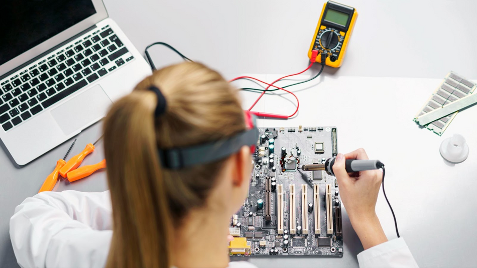
Soldering Equipment
Soldering equipment is crucial for PCB mounting. The components of electronic devices are connected to a pc board (PCB) through soldering, which involves melting a metal alloy (solder) to form a bond between the component and the board. Soldering ensures secure and reliable connections between the components and the board, making it an essential process in the manufacturing and repair of electronic devices. Some of the essential soldering tools and equipment include:
Soldering iron or soldering station: Used for melting solder and creating joints between components and the PCB.
Solder: A metal alloy that melts at a relatively low temperature, used to form connections between components and the board.
Flux: A chemical agent that helps clean and prepare surfaces for soldering, improving the quality of the solder joint.
Soldering tip cleaner: Used to clean and maintain the soldering iron tip, ensuring optimal performance and heat transfer.
In addition to the essential soldering tools and equipment mentioned, other factors must be considered when selecting the appropriate soldering equipment. One of the critical factors to consider is the temperature control of the soldering iron or soldering station. The temperature control ensures that the soldering iron's tip maintains a consistent temperature, which is necessary for producing high-quality solder joints. Temperature control also prevents overheating, which can damage the components or PCB.
Tip size is another essential factor to consider when selecting soldering equipment. The tip size determines the amount of heat transferred to the joint and the precision of the soldering process. A smaller tip is ideal for delicate components, while a larger tip is suitable for larger components and boards.
When selecting flux, it is essential to consider the type of solder being used. Different solders require different types of flux, and using the wrong flux can affect the quality of the solder joint. PCB mounting blocks are used to connect solder-less connectors to a printed circuit board.
Additionally, flux should be used sparingly and applied only to the areas where soldering is required.
Regular maintenance of soldering equipment is crucial to ensure consistent performance and prolong its lifespan. The soldering tip cleaner, for instance, should be used regularly to remove oxidation and buildup on the tip, ensuring optimal heat transfer and preventing damage to the tip. Additionally, the soldering iron or station should be cleaned regularly to prevent the buildup of flux and other residues, which can affect the quality of the solder joint.
It is essential to note that while soldering is an efficient and reliable method of connecting components to the PCB, it is not without limitations. One potential weakness of soldering is that it can produce brittle joints, which can break under stress or strain. Additionally, soldering can be a time-consuming process, particularly when working with complex or delicate components.
To overcome these limitations, alternative methods such as conductive adhesives and mechanical fasteners have been developed. Conductive adhesives provide a more flexible and durable joint, while mechanical fasteners offer a quick and easy method of securing components to the board. However, soldering remains the most common and reliable method of connecting components to the PCB.
Soldering equipment is essential for PCB mounting, and selecting the appropriate equipment and maintaining it regularly are crucial to ensuring consistent performance and prolonging its lifespan. While soldering has limitations, it remains the most common and reliable method of connecting components to the PCB.
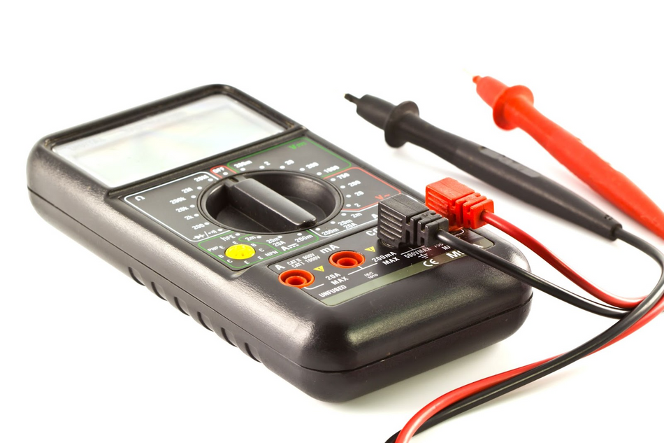
Inspection and Testing Tools
Inspection and testing tools are essential for verifying the quality and functionality of mounted PCBs. Some common inspection and testing tools include:
Magnifying glass or microscope: Used to inspect solder joints and component placement for defects or misalignments. This tool is particularly helpful in identifying issues with smaller components, which may be difficult to spot with the naked eye.
Multimeter: A versatile tool that measures various electrical properties, such as voltage, current, and resistance, to help diagnose issues in the assembled PCB.
Continuity tester: A device that checks for proper electrical connections between components and the board. This tool ensures that the PCBs electrical pathways are properly connected, preventing any short circuits or other issues.
In-circuit tester (ICT) or automated test equipment (ATE): Advanced testing equipment used in high-volume production environments to test PCB functionality quickly and accurately.
However, it's important to note that these tools have limitations and potential biases. For instance, a magnifying glass or microscope may not be able to detect certain
defects or misalignments in the PCB. Multimeters and continuity testers may also produce inaccurate results if not calibrated regularly.
Therefore, it's crucial to use these tools alongside other inspection methods, such as visual inspections and functional tests, to ensure that the PCB is functioning correctly. Additionally, it's essential to consider the specific requirements of the PCB and components being tested to select the most suitable testing equipment.
Inspection and testing tools are essential for verifying the quality and functionality of mounted PCBs. These tools, such as magnifying glasses or microscopes, multimeters, continuity testers, and advanced testing equipment, are designed to identify defects or misalignments and diagnose issues in the assembled PCB. However, it's important to consider the limitations and potential biases of these tools and use them alongside other inspection methods to ensure reliable results. Regular calibration and maintenance of testing equipment are also vital to ensure accuracy.
Best Practices for PCB Mounting
To ensure optimal performance and dependability of mounted PCBs, best practices must be followed throughout the mounting process. In this section, we'll go over some of the most critical PCB mounting best practices, such as accurate component placement, effective soldering procedures, and comprehensive inspection and testing.
Proper Component Placement
Ensuring correct component placement is critical for the functionality and reliability of the assembled pcb board. Some tips for proper component placement include:
Double-checking component orientation and polarity before placing them on the board.
Using a component placement machine or pick-and-place machine for accurate and efficient placement of SMT components.
Ensuring adequate spacing between components to avoid short circuits, facilitate heat dissipation, and allow for easy inspection and maintenance.
To address these limitations, it is essential to have a thorough understanding of the PCB design and its requirements. This includes reviewing the placement requirements and any electrical or mechanical specifications for the components. Additionally, verifying component placement through visual inspection or automated testing can provide added assurance.
When it comes to proper component placement, there is no substitute for attention to detail and careful consideration. Taking the time to ensure correct component orientation, spacing, and placement can save time and money in the long run by reducing the likelihood of errors and failures.
In addition, it is important to consider the impact of component placement on the overall manufacturability of the PCB. Components placed in difficult-to-access locations may be more difficult to rework or repair if needed, leading to increased costs and potential delays. Design for manufacturability (DFM) principles should be considered during the design phase to ensure optimal component placement for both functionality and ease of assembly.
Effective Soldering Techniques
Effective soldering techniques are essential for creating reliable and long-lasting connections between components and the PCB. Some best practices for soldering include the following:
Preheating reduces thermal stress and prevents component breakage, especially in the case of through-hole components. When components are warmed, heat transfer is more consistent while soldering, and the components are less prone to break or become damaged.
Applying an appropriate amount of flux to clean and prepare surfaces for soldering. Flux is an important part of the soldering process because it cleans and prepares surfaces for soldering by eliminating oxides and other impurities. Flux treatment ensures robust solder junctions while reducing the likelihood of cold solder joints.
Using the correct soldering iron temperature and solder type for the specific components and board materials. Too low a soldering iron temperature might result in cold solder junctions, while too high a temperature can harm components or the board itself. The temperature range advised varies based on the type of components and board material used, and it is critical to follow the manufacturer's specifications for each given scenario. When choosing a solder type, it is critical to examine the board's and components' materials, as well as the PCB's intended application.
Thorough Inspection and Testing
Conducting thorough inspection and testing of mounted PCBs helps identify and address potential issues before they become critical problems. Some tips for effective inspection and testing include:
Inspecting solder joints for defects such as cold solder joints, solder bridges, or insufficient solder.
Using a magnifying glass or microscope to inspect small or densely populated areas of the PCB.
Performing functional testing of the assembled PCB to ensure that it operates as intended under various conditions. Functional testing is a critical step in ensuring the reliability and performance of electronic devices, particularly those containing printed circuit boards (PCBs). It involves testing the device under various conditions to verify that it meets its intended specifications and performs as expected.
In addition to verifying that the device performs its intended functions, functional testing can also identify potential issues such as intermittent failures, incorrect firmware, or software errors. Some common methods for functional testing include boundary scan testing, in-circuit testing, and functional testing using test fixtures or automated test equipment.
Boundary scan testing, also known as JTAG (Joint Test Action Group) testing, is a method that uses special test circuits integrated into the PCB to test individual components and their connections. In-circuit testing involves using a bed-of-nails test fixture to make contact with various points on the PCB and test the components and connections. Functional testing using test fixtures or automated test equipment involves testing the device using simulated inputs and verifying that it produces the expected outputs.
It's important to note that functional testing is just one part of the overall testing process for electronic devices. Other types of testing, such as environmental testing (to ensure the device can withstand extreme temperatures, humidity, or other environmental factors) and reliability testing (to test the device's long-term durability), may also be necessary depending on the intended application of the device.
One potential weakness of inspection and testing is the reliance on human inspection, which can be prone to errors and inconsistencies. Additionally, functional testing may not be able to detect certain issues or defects that may only occur under specific conditions or over a longer period of time.
By following these best practices and using the appropriate tools and equipment, you can significantly improve the quality and reliability of your mounted PCBs, ensuring optimal performance in their intended applications.
Recommended reading: Test PCB: Everything You Need to Know
Conclusion
We've covered the most important aspects of PCB mounting in this thorough guide, including considerations to consider before mounting, common mounting techniques, necessary tools and equipment, and best practices for ensuring optimal performance and dependability. You'll be well-equipped to undertake PCB mounting projects with confidence and success if you understand these ideas and apply the strategies described. Mastering the art of PCB mounting will remain a crucial ability for professionals in the business as the world of electronics continues to evolve and grow in complexity.
Frequently Asked Questions (FAQs)
What is the difference between SMT and THT mounting techniques?
Surface Mount Technology (SMT) involves attaching components directly to the surface of the PCB, while Through-Hole Technology (THT) requires inserting component leads through holes in the board and soldering them on the opposite side. Simply insert screws into the mounting holes on your circuit board, and their flanged construction keeps them in place without the use of screws. In mounting holes, a self-tapping screw can be utilised.
SMT is generally faster and allows for higher component density, while THT provides greater mechanical strength and is easier to hand-solder.
How do I choose the right mounting technique for my PCB?
The choice of mounting technique depends on factors such as component density, board size, mechanical strength requirements, and ease of assembly. SMT is best suited for high-density, compact designs, while THT is ideal for applications requiring robust connections and easier soldering. Mixed technology mounting can be used to leverage the advantages of both techniques.
What are some common mistakes to avoid during the PCB mounting process?
Common mistakes include incorrect component placement or orientation, poor soldering techniques leading to weak or faulty connections, and insufficient inspection and testing of the assembled PCB. Following best practices and using the appropriate tools and equipment can help minimise these issues.
How can I improve the thermal management of my mounted PCB?
Effective thermal management can be achieved through proper component placement, the use of heat sinks or thermal vias, and ensuring adequate airflow around heat-generating components. Considering thermal requirements during the design and mounting process can help maintain optimal performance and reliability.
What are the essential tools and equipment needed for PCB mounting?
Essential tools and equipment for PCB mounting include soldering equipment (soldering iron or station, solder, flux, and tip cleaner), inspection and testing tools (magnifying glass or microscope, multimeter, continuity tester, and in-circuit tester or automated test equipment), and component placement machines for SMT assembly.
References
The Influence of PCB Mounting/Interconnection Technologies into the Design of a Part (EXTERNAL)