Contactor vs Relay: Understanding the Differences and Applications
This article aims to provide a comprehensive comparison between contactors and relays, highlighting their key differences, applications, and factors to consider when choosing the right device for your needs.

20 Sep, 2023. 18 minutes read
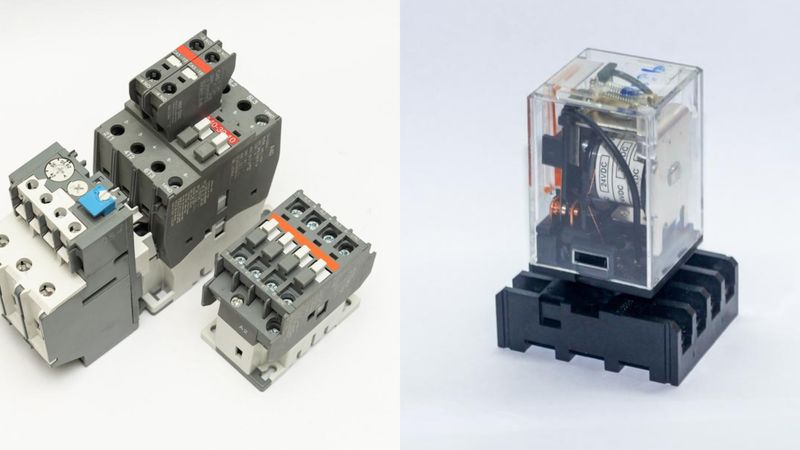
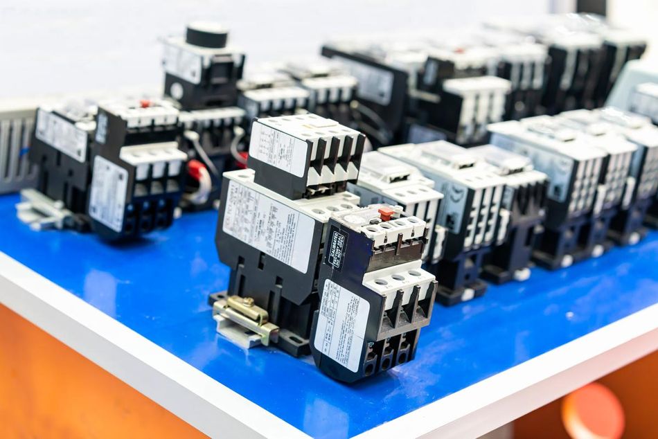
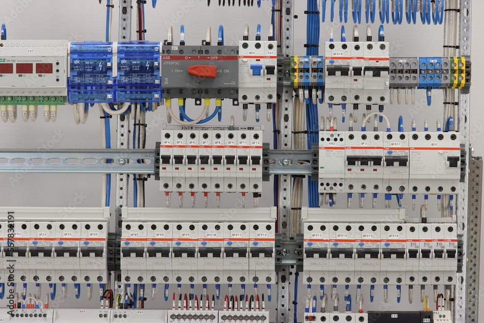
Contactor vs relay used in electrical devices
No time now? Save for later.
We only use your email to send this link. Privacy Policy.
Introduction
Contactors and relays are essential components in electrical systems, serving as switches for controlling power flow. Both devices share similarities in their basic function, so there is usually confusion about the difference between a contactor vs relay! Typically used for switching the loads, contactors and control relays are integrated into an electrical circuit subject to the resultant load. A wrong decision in deciding the electrically operated switches for a particular application can cost a huge amount of investment, damaging the integrated electrical circuit. By understanding the fundamental principles and technical aspects of contactor vs relay, you will be better equipped to make informed decisions when designing or maintaining electrical systems.
Basic Definitions
What is a Contactor?
A contactor is an electromechanical switch designed to control the flow of electrical current in high-power applications. It consists of three main components: a coil, contacts, and an enclosure. When energized, the coil generates a magnetic field, which attracts the contacts, causing them to close and complete the circuit. This allows the flow of current through the connected electrical load.
Contactors are typically used in applications where high currents, typically above 15 amperes, need to be switched on and off [7]. These are known for their capability to handle currents of over 5000 amperes and high power over 100 kW. [1] Contactors are designed to handle high inrush currents when starting large motors or other inductive loads. The contacts in a contactor are usually made of materials with high electrical conductivity, such as silver or copper, to minimize contact resistance and ensure efficient current flow. The enclosure, often made of plastic or metal, protects against environmental factors and electrical hazards.
One of the key features of contactors is their ability to handle high currents while maintaining a relatively small form factor. This is achieved through arc suppression techniques, such as arc chutes or blowout magnets, which help extinguish the electrical arc that forms when the contacts open or close. These features enable contactors to operate reliably and safely in demanding electrical environments.
What is a Relay?
A relay is an electromechanical or solid-state device that serves as a switch to control the flow of electrical current in low to medium-power applications. It consists of a coil, contacts, and an enclosure similar to a contactor. When the coil is energized, it generates a magnetic field that attracts the contacts, either closing or opening the circuit, depending on the relay's configuration. This allows the flow of current through the connected electrical load.
Relays are commonly used in applications with lower current requirements, typically below 15 amperes. They are often employed to control smaller loads or as an intermediary between a low-power control signal and a higher-power load. The contacts in a relay can be made of various materials, such as silver or gold, depending on the specific application requirements. The enclosure, typically plastic, protects against environmental factors and electrical hazards.
One of the main advantages of relays is their ability to isolate the control circuit from the load circuit. This means that a low-power control signal can switch a higher power load without the risk of electrical interference or damage to the control circuit. Additionally, relays can be designed with multiple contacts, allowing them to control multiple circuits simultaneously. These also provide different switching configurations, such as single-pole double-throw (SPDT) or double-pole double-throw (DPDT) arrangements. [2]
Key Differences Between Contactors and Relays
Load Capacity
Load capacity is the maximum allowable force that can be applied to a stage in a specified direction while meeting stage specifications. [3] One of the primary differences between contactors and relays is their load capacity. Contactors are designed to handle high-current loads, while relays are suitable for low to medium-current loads. This difference in load capacity results from the design and construction of the devices, with contactors featuring larger and more robust auxiliary contacts to accommodate higher currents. Special contactors are utilized to switch three phases of power simultaneously.
In practical terms, contactors are often used in applications involving large motors, heavy machinery, or other high-power equipment, where the current requirements can reach hundreds or even thousands of amperes. On the other hand, relays are more commonly found in control systems, automation, and low-power devices, where the current requirements are relatively modest. Relays are typically limited to single-phase applications.
The choice between a contactor and a relay for a specific application depends on the current requirements of the load. When starting motors or inductive loads, considering both the continuous current rating and the initial surge of current, known as inrush current, is essential. Selecting a device with an appropriate load capacity ensures reliable operation and minimizes the risk of device failure.
Switching Mechanism
Switching is a way to control continuity between two points in an electrical circuit. [4] Another key difference between contactors and relays is the way they switch electrical currents. Both devices use an electromechanical mechanism, where an energized coil generates a magnetic field that attracts the spring-loaded contacts, either opening or closing the circuit. However, the specific design and construction of the switching mechanism can vary between the two devices, leading to differences in performance and suitability for specific applications.
In contactors, the switching mechanism is designed to handle high currents and minimize the effects of electrical arcing. This is achieved through the use of arc suppression techniques, such as arc chutes or blowout magnets, which help extinguish the electrical arc that forms when the contacts open or close. Contactors typically have larger contacts made of materials with high electrical conductivity, like silver or copper. This ensures efficient current flow by minimizing contact resistance.
Conversely, relays have a more compact switching mechanism, suitable for lower current applications. The contacts in relays can be made of various materials, such as silver or gold, depending on the specific application requirements. Relays are less robust than contactors in preventing wear and damage caused by electrical arcing in high-current situations. Capacitor banks can be used to reduce the inrush current when a relay switches on a high-power load.
The choice between a contactor and a relay for a specific application depends on the switching requirements, including the current levels, the frequency of switching, and the need for arc suppression. Selecting the most appropriate device for your application minimizes the risk of device failure or damage to the connected equipment.
Recommended reading: Switching vs Linear Power Supply: What's the difference
2.3. Open/closed contact standards
Relays are designed to operate both normally open and normally closed depending on the required function, but contactors are designed to operate with normally open contacts. This means there is no contactor connection when the coil is de-energized, which is not necessarily true regarding relays.

Easy to remember:
Normally closed (NC) = Current flows
Normally open (NO) = Current does not flow
In normally open conditions, no current flow is in its normal or initial state. But energizing it and switching it on will close the contacts to allow it to flow current. On the other hand, normally closed in NC contacts is a condition with a flow of current in its normal or initial state. But contrary to what happens in NO, de-energizing and switching it on will open the contact to stop the current flow. Contactors are typically used to switch high-voltage circuits, while relays are typically used to switch low-voltage circuits.
2.4. Size and Construction
The size and construction of contactors and relays also differ, with each device designed to accommodate its intended applications and load capacities.
Contactors are generally larger and more robust than relays due to their ability to handle high currents. The contacts in contactors are typically made of materials with high electrical conductivity to minimize contact resistance and ensure efficient current flow. Contactors are typically designed to handle AC and DC loads; their coil draws significant power. Additionally, they come with provisions for arc suppression to prevent any damage from electrical arcing.
Conversely, relays are more compact and lightweight, making them suitable for low to medium-current applications. The contacts in relays can be made of various materials depending on the specific application requirements. They are designed to open or close circuits electronically or electromechanically. Since they manage smaller loads, relays don’t usually require the same level of arc suppression as contractors.
When selecting between a contactor and a relay for a specific application, it is essential to consider the size and construction requirements of the device. This includes factors such as available space, mounting options, and environmental conditions. By understanding the differences in size and construction between contactors and relays, you can choose the most appropriate device for your application, ensuring reliable operation and minimizing the risk of device failure or damage to the connected equipment.
2.5. Electrical Noise
Electrical noise, or electromagnetic interference (EMI), is an unwanted electrical signal disturbance affecting electronic devices' performance and reliability. Contactors and relays, as electromechanical switches, can generate electrical noise during their operation, with the level of noise depending on the design and construction of the device.
Due to their larger size and higher current handling capabilities, contactors can generate more electrical noise than relays. The opening and closing of contacts in a contactor can create electrical arcs, which produce electromagnetic radiation that can interfere with nearby electronic devices. To mitigate this issue, contactors often employ arc suppression techniques to extinguish the electrical arc and reduce the amount of electrical noise generated.
Conversely, relays generate less electrical noise due to their smaller size and lower current handling capabilities. However, they can still produce some electrical noise during their operation, particularly when switching inductive loads. Solid-state relays use semiconductor components that offer lower levels of electrical noise, making them suitable for applications where EMI is a concern.
When choosing between a contactor and a relay for a specific application, it is essential to consider the potential impact of electrical noise on the performance and reliability of the connected equipment. In situations where EMI is a concern, such as in sensitive electronic systems or environments with strict electromagnetic compatibility (EMC) requirements, selecting a device with lower electrical noise generation may be more appropriate.
2.6. Lifespan and Durability
The lifespan and durability of contactors and relays are important factors when selecting the appropriate device for a specific application. Both devices are subject to wear and tear due to their electromechanical nature. Still, the extent of wear and the expected lifespan can vary depending on the design, construction, and operating conditions.
Contactors, designed to handle high currents, typically have a longer lifespan and greater durability than relays. The contacts in contactors are made of materials with high electrical conductivity, which minimize contact resistance and ensure efficient current flow. Additionally, contactors often employ arc suppression techniques which help extinguish the electrical arc that forms when the contacts open or close, reducing wear on the contacts and extending the device's lifespan.
Relays have a shorter lifespan and lower durability than contactors due to their smaller size and lower current handling capabilities. The contacts in relays wear out more quickly than those used in contactors, particularly when switching inductive loads or operating at high frequencies. Solid-state relays offer improved durability and longer lifespans compared to electromechanical relays. Still, they may not be suitable for all applications due to their specific characteristics and limitations.
Factors that can affect the lifespan and durability of contactors and relays include the frequency of switching, the current and voltage ratings, and the type of load being switched. This also includes the environmental conditions, such as temperature, humidity, and the presence of dust or corrosive substances. By understanding the differences in lifespan and durability between contactors and relays, you can select the right device to ensure reliable operation and minimize the risk of device failure.
Recommended reading: General Purpose Port Protection Against Electrical Stress
| Parameters | Contactor | Relay |
| Definition | An electromagnetic switch that can carry a current load of up to 12,000 amperes | An electromagnetic switch that can carry a current load of up to 10 amperes |
| Size | Large in size | Comparatively smaller or of the same size as the contactor |
| Cost | More cost | Less cost |
| Auxiliary Contacts | It consists of at least one set of three-phase power contacts, and built-in auxiliary contacts can also be present | Comes with at least two contacts-NC and NO |
| Load | 9A and above | 10A or below |
| Voltage | Maximum 1000 volts | Maximum 250 volts |
| Phase | 1 or 3 phase | 1 phase |
| Life Span | Shorter | Longer |
| Switching Device Speed | The average switching speed for a contactor is between 20 and 250 | The average switching speed for a relay is between 3 and 100 ms |
| Coil Power Troubleshooting | More coil power consumption | Less coil power consumption |
| Troubleshooting | They do not come with any troubleshooting features | Relays have better troubleshooting features, such as flags or small lights indicating the position of the relay |
| Humming Noise | Sound level of humming noise is higher | The sound level is lesser than that of a contactor |
| Maintenance | Requires more maintenance | Requires less maintenance |
| Applications | At least three-phase electrical networks, such as transformer or induction motor | Single-phase applications |
Applications of Contactors and Relays
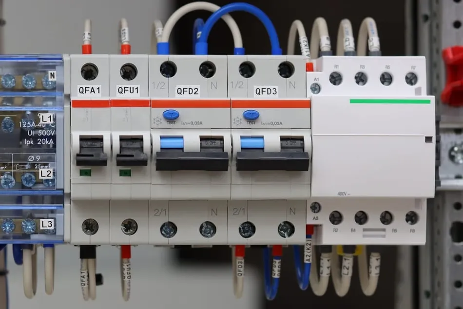
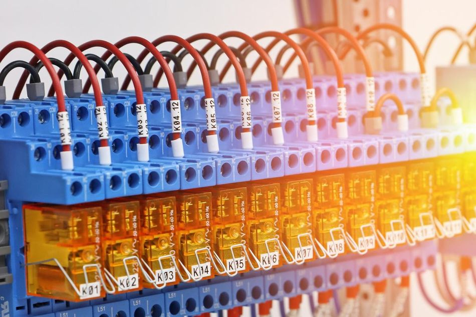
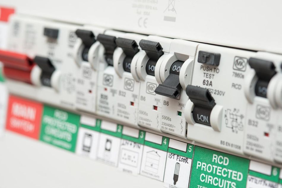
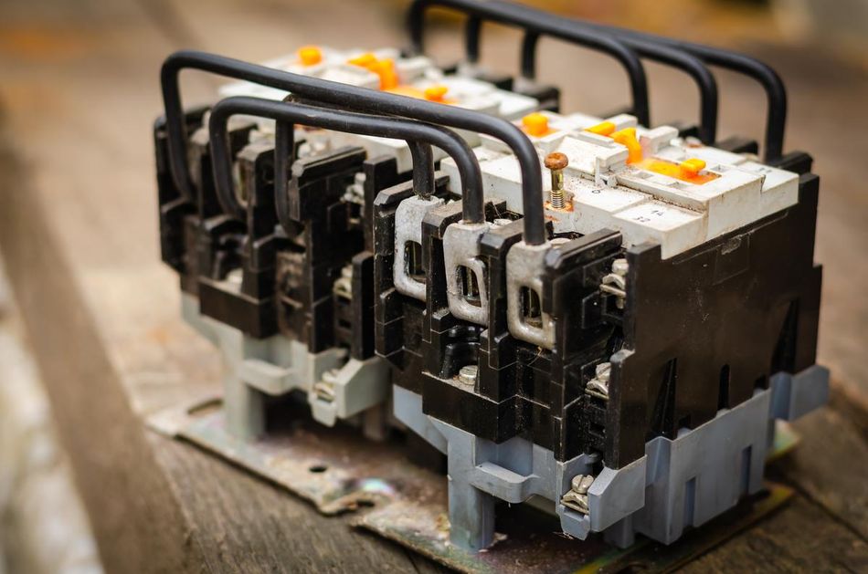
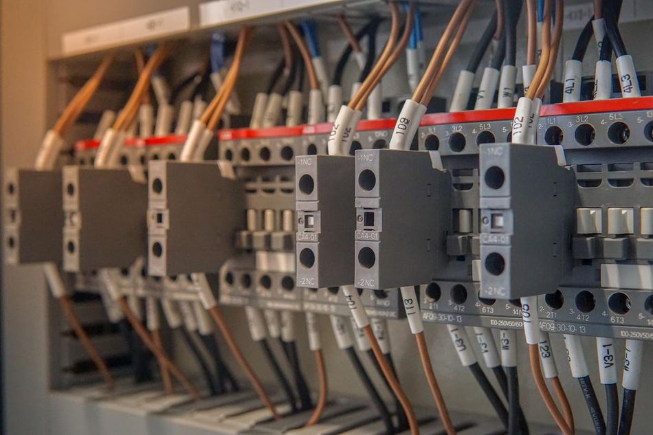
 Contactors and relays for electric equipment motor starter control and industrial machines
Industrial Applications
Contactors and relays are crucial in controlling and managing electrical loads in industrial settings. Their specific applications depend on load capacity, switching requirements, and environmental conditions.
Contactors are commonly used in industrial applications involving high-power equipment, such as large motors, heavy machinery, heating, ventilation, and air conditioning (HVAC) systems. These devices require high current handling capabilities, which contactors are designed to accommodate. For instance, contactors can be found in motor control centers responsible for starting and stopping large motors and providing overload protection. [5] Additionally, contactors can be used in power distribution systems to control the flow of electricity to various parts of an industrial facility. In automotive applications, contactors are typically used for high-power loads, including starter motors, EV motors, air conditioning compressors, and electric power steering motors.
Relays, on the other hand, are more suitable for low to medium-current applications in industrial environments. They are often employed in control systems, automation, and safety circuits, where their ability to isolate the control circuit from the load circuit is essential. For example, relays can be used in programmable logic controllers (PLCs) to control the operation of machinery or in safety systems, such as emergency stop circuits, to ensure the safe operation of equipment. Relays can also be found in monitoring and alarm systems, which activate alarms or initiate corrective actions in response to specific conditions, such as temperature or pressure deviations.

By understanding the specific requirements of industrial applications and the capabilities of contactors and relays, you can select the most appropriate device, ensuring reliable operation and optimal performance of your electrical systems.
Commercial Applications
In commercial environments, contactors and relays control and manage electrical loads in various applications.
Contactors are often employed in commercial applications that involve high-power equipment, such as HVAC systems, lighting control, and large appliances. For example, contactors can be used in commercial buildings to manage the operation of air conditioning units, ensuring efficient energy usage and maintaining a comfortable indoor environment. In lighting control systems, contactors can be utilized to switch large groups of lights on and off, either manually or based on a predetermined schedule, helping to reduce energy consumption and extend the lifespan of the lighting equipment.
Relays, on the other hand, are more suitable for low to medium-current applications in commercial settings. They are commonly found in control systems, automation, and safety circuits, where their ability to isolate the control circuit from the load circuit is essential. For instance, relays can be used in building automation systems to control various aspects of the building's operation, such as lighting, heating, and security. In safety systems, relays can be employed to monitor and control emergency lighting, fire alarms, and access control systems, ensuring the safety and security of the building's occupants.
By understanding the specific requirements of commercial applications and the capabilities of contactors and relays, you can select the most appropriate device, ensuring reliable operation and optimal performance of your electrical systems.
Residential Applications
In residential environments, contactors and relays have various applications in controlling and managing electrical loads.
Contactors are used in residential applications that involve high-power equipment, such as central air conditioning systems, electric water heaters, and solar power installations. For example, contactors can be employed in solar power installations; contactors can be utilized to switch between grid power and solar power, depending on the availability of solar energy and the requirements of the electrical loads in the home. [6]
Relays are more suitable for low to medium-current applications in residential settings. Relays can be used in home automation systems to control various aspects of the home's operation, such as lighting, heating, and security. In safety systems, relays can be employed to monitor and control smoke detectors, carbon monoxide alarms, and security systems, ensuring the safety and security of the home's occupants.
By understanding the specific requirements of residential applications and the capabilities of contactors and relays, you can select the most appropriate device, ensuring reliable operation and optimal performance of your electrical systems.
Recommended reading: Innovative Transformer Solution Addresses Traditional Challenges
Selecting the Right Device for Your Application
Load Requirements
When choosing between a contactor and a relay for a specific application, the load requirements is one of the most critical factors to consider. This includes both the continuous current rating and the inrush current, which is the initial surge of current that occurs when starting a motor or other inductive loads.
To determine the load requirements, you should first identify the current and voltage levels of the electrical load you need to control. This information can typically be found on the equipment's nameplate or in the manufacturer's documentation. It is essential to select a device with a continuous current rating that meets or exceeds the maximum current requirement of the load. Additionally, consider the inrush current, which can be significantly higher than the continuous current rating, especially for inductive loads like motors.
Once you have determined the load requirements, you can compare the specifications of contactors and relays to find a suitable device. Contactors are generally more appropriate for high-current applications, while relays are better suited for low to medium-current applications. By selecting a device with the appropriate load capacity, you can ensure reliable operation and minimize the risk of device failure or damage to the connected equipment.
Environmental Factors
Environmental factors can also play a significant role in determining the most suitable device, whether a contactor or a relay, for your specific application. These factors include temperature, humidity, dust, and the presence of corrosive substances, which can affect the performance, reliability, and lifespan of the device.
Contactors, with their robust construction and larger size, are generally better suited for harsh environments. where high temperatures, humidity, or dust may be present. The enclosures of contactors, typically made of plastic or metal, protect against environmental factors and electrical hazards. Additionally, contactors often feature arc suppression techniques, such as arc chutes or blowout magnets, which help extinguish the electrical arc that forms when the contacts open or close, reducing wear on the contacts and extending the device's lifespan.
Relays are more compact and may be less resistant to harsh environmental conditions. The enclosures of relays, typically made of plastic, protect against environmental factors and electrical hazards but may not be as durable as the enclosures used in contactors. Solid-state relays, which use semiconductor components instead of mechanical contacts, can offer improved resistance to environmental factors. Still, they may not be suitable for all applications due to their specific characteristics and limitations.
When selecting between a contactor and a relay for a specific application, it is essential to consider the environmental conditions in which the device will operate. By understanding the differences in the construction and materials used in contactors and relays, you can choose the most appropriate device to ensure reliable operation.
Cost Considerations
Cost considerations can be significant in the decision-making process when selecting between a contactor and a relay for a specific application. The costs associated with these devices can vary depending on factors such as load capacity, construction materials, and additional features, such as arc suppression techniques.
Contactors, due to their larger size and higher current handling capabilities, are generally more expensive than relays. The materials used in contactors, such as silver or copper contacts, can contribute to their higher cost. Additionally, the arc suppression techniques employed in contactors, such as arc chutes or blowout magnets, can add to the overall cost of the device.
Relays, on the other hand, are typically less expensive than contactors, making them a more cost-effective option for low to medium-current applications. However, the cost of relays can vary depending on the specific materials used for the contacts, such as silver or gold, and the type of relay, such as electromechanical or solid-state. Solid-state relays, which use semiconductor components instead of mechanical contacts, can be more expensive than electromechanical relays but offer improved durability and lower electrical noise generation.
When considering the cost of contactors and relays; it is essential to factor in the initial purchase price and the long-term costs associated with the device, such as maintenance, replacement, and energy consumption. By understanding the cost implications of contactors and relays and considering the specific requirements of your application, you can make an informed decision that balances performance, reliability, and cost-effectiveness.
Installation and Maintenance
Installing Contactors and Relays
Proper installation of contactors and relays is essential to ensure reliable operation and minimize the risk of device failure or damage to the connected equipment. While the specific installation procedures may vary depending on the manufacturer's recommendations and the type of device, some general guidelines can be followed for both contactors and relays.
Choose the appropriate location: Select a suitable location for the device, considering available space, mounting options, and environmental conditions. Ensure that the device is installed in a clean, dry, and well-ventilated area, away from heat, moisture, or excessive vibration sources.
Mount the device securely: Use the appropriate mounting hardware, such as screws or DIN rail clips, to securely attach the device to a panel, enclosure, or other suitable surface. Ensure that the device is mounted in the correct orientation, as the manufacturer specifies.
Wire the device according to the manufacturer's instructions: Follow the wiring diagram and guidelines to connect the device to the control circuit and the load. Use the appropriate wire size and type, as specified by the manufacturer, and ensure that all connections are secure and properly insulated.
Verify proper operation: Before energizing the device, double-check all connections and ensure that the device is installed and wired correctly. Once the device is energized, test its operation by manually activating the control circuit and observing the response of the load. Verify that the device operates as expected and that there are no signs of overheating, arcing, or other issues.
By following these general guidelines and the specific instructions provided by the manufacturer, you can ensure a successful installation of contactors and relays, providing reliable operation and minimizing the risk of device failure or damage to the connected equipment.
Troubleshooting and Maintenance

Regular maintenance and timely troubleshooting of contactors and relays work is essential to ensure their reliable operation and extend lifespan. While the specific maintenance procedures and troubleshooting steps may vary depending on the manufacturer's recommendations and the type of device, some general guidelines can be followed for both contactors and relays.
Inspect the device regularly: Perform visual inspections to check for wear, damage, or contamination signs. Look for signs of overheating, such as discoloration or deformation of the enclosure or contacts. Check for loose or corroded connections, leading to increased resistance and reduced performance.
Clean the device as needed: Remove dust, dirt, and other contaminants using a soft brush or compressed air. Be cautious not to damage the main contacts or other sensitive components during cleaning. If necessary, use a mild cleaning solution and a soft cloth to remove stubborn dirt or grease, but ensure the device is completely dry before re-energizing it.
Check the contacts for wear: Examine the set of contacts for signs of wear, such as pitting, erosion, or excessive buildup of contact material. If the power contacts are severely worn or damaged, these may need to be replaced to maintain reliable operation. Consult the manufacturer's guidelines for specific information on contact replacement and maintenance intervals.
Test the device's operation: Periodically test the operation of the contactor or relay by manually activating the control circuit and observing the response of the load. Verify that the device operates as expected and that there are no signs of abnormal behavior, such as chattering, arcing, or excessive noise.
Monitor the device's performance: Keep track of the device's performance over time, noting any changes in operation, such as increased response times, reduced contact force, or increased electrical noise. These changes may indicate that the device requires maintenance or replacement.
By following these general guidelines and the specific instructions provided by the manufacturer, you can ensure the proper maintenance and troubleshooting of contactors and relays, providing reliable operation and minimizing the risk of device failure or damage to the connected equipment.
Conclusion
In summary, contactors and relays are essential components in electrical systems, serving as switches for controlling power flow. While they share similarities in their basic function, they differ in load capacity, switching mechanisms, size, construction, electrical noise generation, and lifespan. Understanding these differences and considering factors such as load requirements, environmental conditions, and cost can help you select the most appropriate device for your specific application, ensuring reliable operation and optimal performance of your electrical systems.
Frequently Asked Questions (FAQs)
1. What is the main difference between a contactor and a relay?
A. The main difference between a contactor and a relay is their load capacity. Contactors are designed to handle high currents, typically above 15 amps, while relays are more suitable for low to medium current loads, usually below 15 amps.
2. Can a relay be used in place of a contactor?
A. Relays can sometimes be used in place of contactors for low to medium-current applications, but they may not be suitable for high-current applications due to their lower current handling capabilities and reduced durability compared to contactors.
3. What are some common applications of contactors and relays?
A. Contactors are commonly used in high-power applications, such as large motors, heavy machinery, and HVAC systems. Relays are often employed in control systems, automation, and low-power circuits, where their ability to isolate the control circuit from the load circuit is essential.
4. How do I choose between a contactor and a relay for my application?
A. To choose between a contactor and a relay, consider load capacity, switching requirements, environmental conditions, and cost factors. By understanding the differences between these devices and considering the specific requirements of your application, you can select the most appropriate device for your needs.
5. How can I extend the lifespan of my contactor or relay?
A. Regular maintenance, such as visual inspections, cleaning, and testing, can help extend the lifespan of contactors and relays. Additionally, ensuring proper installation and following the manufacturer's guidelines for operation and maintenance can contribute to the longevity of these devices.
References
[1] c3controls. THE BASICS OF A CONTACTOR & DIFFERENT TYPES OF CONTACTOR DEVICES. [Cited 2023 September 17] Available at: Link
[2] Galco. RELAYS – HOW RELAYS WORK. [Cited 2023 September 17] Available at: Link
[3] ScienceDirect. Load Capacity. [Cited 2023 September 17] Available at: Link
[4] Allaboutcircuits. Selector Switches. [Cited 2023 September 17] Available at: Link
[5] c3controls. OVERLOAD RELAYS: TYPES & TRIPPING & WHAT IS OVERLOAD PROTECTION? [Cited 2023 September 17] Available at: Link
[6] Veris. What is a Relay? Relay Types, How They Work, & Applications [Cited 2023 September 17] Available at: Link
[7] IEC 60947-4-1:2021. *Low-voltage Switchgear and Controlgear — Part 4-1: Contactors and Motor-Starters — Electromechanical Contactors and Motor-Starters.* International Electrotechnical Commission, Geneva. https://webstore.iec.ch/publication/66353
in this article
1. Introduction2. Basic Definitions3. Key Differences Between Contactors and Relays4. Applications of Contactors and Relays5. Contactors and relays for electric equipment motor starter control and industrial machines6. Selecting the Right Device for Your Application7. Installation and Maintenance8. Conclusion9. Frequently Asked Questions (FAQs)10. ReferencesNo time now? Save for later.
We only use your email to send this link. Privacy Policy.