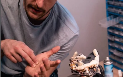
InMoov 3D Printed Hand and Forarm
An open-source 3D printed hand and forearm design for robotics enthusiasts.
Technical Specifications
| Purpose | EdTech |
| Operation | Sensor-based Feedback Control |
| Microcontroller | Arduino Uno/Nano |
Overview
Innovative and Sophisticated Design for Robot Lovers
Thanks to an open-source design, the robot can be assembled by anyone with the prerequisite knowledge of Arduino programming and hands-on practice with electronic components.
The robotic hand uses an array of touch sensors installed at the fingertips. The sensor feedback is received by an Arduino microcontroller that controls the movements and hand gestures. The 3D-printed design is meant for an Arduino Uno microcontroller. However, based on the required functionality, it can also work with an Arduino Nano.
Moreover, the array of servo motors includes five servo motors with a 90-degree rotational limit. These servos control finger movement. Also, an additional servo motor for wrist movement can rotate up to 180 degrees.
3D- Printing Guide for Robotic Parts
Each 3D-printed part has a unique design and features varying thicknesses. Therefore, the following design guide is critical to follow:
All parts must be printed with a 30% infill
The parts for the wrist, thumb, and forearm must have a 2mm printing thickness
The fingers must be printed with a 1.5mm thickness.
All parts can be combined with Acetone, Epoxy, or ABS.
It’s best to use a knife to trim off the edges to give a smooth finish
Avoid using glue on the outside. Otherwise, the robotic arm won’t look clean
Ensure the parts are well aligned and don’t need to be dismantled and glued again.
Easy to Build Robotic Platform with a Comprehensive Guide
The stand-out feature of this robotic hand and forearm is the availability of all the content that goes into making this robot. So, a user needs a 3D printer and a collection of electronics to assemble and test the design.
For further simplicity, the functionality and design of both hands are entirely similar while keeping in mind the mirroring effect. So, the user can follow the same procedure to assemble the left hand as the one used for the right arm.
Hence, once the user has 3D-printed all the required parts, they can follow the following guidelines to complete the robotic hand and forearm.
Hand Assembly
The hand assembly is a critical part of the robot as it features an array of moveable joints and rotary parts. To complete the hand assembly, the user would require 3D-printed parts for each finger and an optional Elbow bicep. Depending on whether the user wants to include elbow functionality, the elbow joint must also be printed for that purpose.
In the first phase, the hand is assembled. It features forearm assembly and installing a servo bed and five servo motors, where each servo controls a finger independently. The servo motors are connected to the finger through a braided fishing line that has a breaking strength of 200 lbs. The fishing lines pass through transparent tubes clamped to the servo bed with a spring. The springs provide the required tension in the tendons for a realistic effect.
Wrist Assembly
The wrist assembly phase consists of installing a servo motor that controls the rotary action in the wrist. The wrist requires the MG996 servo motor, capable of 180-degree rotation. The other servo motors can rotate up to 90 degrees only. The servo assembly goes inside the wrist assembly and is further connected to a geared mechanism to connect to the palm.
Since the wrist servo action needs to be smooth, it’s recommended to use white silicone grease to add more damping and smoothness to the motion. Moreover, the silicone grease also prevents the white parts from getting yellowish after some time.
Finger Tip Assembly
The fingertip assembly is the most detail-oriented step; the user must work with small parts. So, it requires a lightweight and small drill (preferably 3.2 or 3.5 mm). In this step, the user would work with several hinged joints drilling for the fishing wires to pass through to the tip of the fingers. Moreover, each finger contains electrical wires and connectors at the tip. These connectors will be later used to receive input from the fingertip sensors.
Once the fingers and palm are assembled and the braided fishing line is connected, this part can be mounted to the wrist assembly.
Fingertip Sensor Assembly
After the fingers have been assembled, the final step is to install the fingertip sensor to the tip. In this step, the sensor must be glued to the fingertip to receive tactile feedback allowing the robotic hand to take necessary action. As mentioned in the source files, the user can verify the sensor operation and code performance by connecting the signal-carrying wires to the Arduino board.
Once each finger is tested, the robotic hand can be given a makeover. Adding a sponge to the fingers and palm gives it a different look and protection from shocks. At this stage, the InMoov 3D-printed robotic hand and forearm are ready for operation.
References
Recommended Specs
Continue Reading
Clone Robotics’ humanoid hand uses hydraulics to mimic complex human hand function.
From robotic hands and arms to soft heart pumps, biomaterials, 3D-printed muscles and more, rapid advancements in robotics and biotechnology are giving rise to new techniques for repairing the human body.


Learn how Shadow Robot combines deep dexterous robotics expertise with transparent collaboration to move from concept to scalable manipulation systems.