Calibrating Your 3D Printer's Z Offset Setting
Z offset is an important 3D printer setting that allows users to perfect their first layer. It can be adjusted in slicer software or by inputting G-code commands.

Last updated on 14 Nov, 2023. 8 minutes read
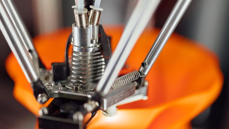
Z offset adjusts the printhead's Z home position
Adjustment of the 3D printer’s Z offset is a way to achieve successful prints in a variety of situations. It is primarily used to ensure the correct distance between the nozzle and print bed when using an auto bed leveling sensor, but it can also be used to solve poor adhesion or when using a thick build surface or substrate.
This article goes over the basics of Z offset, discussing the meaning of the term, the reasons why users might need to incorporate a Z offset, and looking at how to adjust this key parameter in three different ways: using G-code, slicing software, and a 3D printer’s physical LCD display.
What is a Z Offset?
A Z offset is a user-defined print setting that allows the printhead to be positioned above or below the default Z home position. Typically, the input value will be the physical distance between the trigger point of the endstop or Z-probe and the actual tip of the printer nozzle.
A standard Cartesian-style FDM 3D printer has a printhead that moves along three axes. Movement along the X and Y axes allows the printhead to “draw” each 2D layer, while movement along the Z axis allows the printhead to move upwards to the next layer. Because a 3D printer has a fixed build volume, there are limits to how far the printhead can move along any of these three axes. And to prevent the printer from trying to exceed these limits, hardware manufacturers install small sensors called limit switches (or endstops) which detect when a moving part has reached its limit and cannot move any further.
The limit switch on the Z axis is important because it effectively prevents the printhead from burrowing into the build surface, which could potentially cause damage to the print bed and the hotend. The limit switch recognizes when the printhead is at its lowest possible point, and prevents it from descending further. The Z probe on a printer with automatic bed leveling performs the same function.
The “home position” of the printhead more-or-less corresponds to the position where these limit switches kick in. So when a printer is “homed,” the printhead sits in a corner of the print bed, just fractionally above the surface. But sometimes the home position is not exactly where it should be.
The Z offset parameter has other uses too. In fact, a printer user might want the printhead’s default starting position to be slightly higher or lower on the Z axis for several reasons, and a Z offset can be used to do this.
The Difference Between Bed Leveling & Z Offset
Bed leveling and Z offset are both crucial aspects of 3D printing, particularly in ensuring proper adhesion and layer deposition. Bed leveling refers to the process of adjusting the print bed to ensure it is parallel to the printer's movement plane. This is essential for achieving consistent layer adhesion and preventing issues like uneven first layers.
On the other hand, Z offset is a parameter that adjusts the initial height of the print nozzle above the bed. It fine-tunes the distance between the nozzle and the bed during the first layer, compensating for e.g. the small physical gap between the probe tip and the nozzle tip. While bed leveling addresses the overall alignment of the bed, Z offset allows for finer adjustments in the vertical direction, ensuring the correct starting height for the print. Together, these measures contribute to a well-calibrated 3D printing setup, resulting in accurate and reliable prints.
Why Adjust the Z Offset?
It is important to understand that adjustment of the Z offset is not always an essential stage of printer calibration like bed leveling. Bed leveling, which should be performed when a 3D printer is set up or when a new component has been installed, ensures the nozzle is the correct distance from the print bed at every point across the build surface. It is a necessary procedure for preventing print failure.
By contrast, adjusting the Z offset is a secondary step that users may wish to perform in order to accommodate changes to material type or build surface, or simply to achieve a better first layer.
Auto Bed Leveling (ABL)
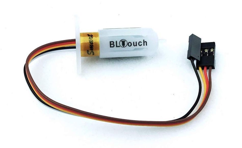
An exception is when using the Z offset parameter to position the nozzle correctly when using auto bed leveling. As mentioned in the previous section, the Z-probe of an ABL system is typically not positioned at exactly the same height as the nozzle tip, so the height at which the probe touches the build surface is not always the same height at which the nozzle touches the build surface.
Without Z offset, this can be an issue, since we want the printer to know how close the build surface is to the nozzle tip, not how close it is to the probe. But we can use the Z offset parameter to tell the printer about this small discrepancy and to adjust the height of the printhead accordingly.
Other reasons for adjusting the Z offset include:
First layer: Setting a Z offset can help achieve a good first layer that is neither too far from the build plate (which can lead to adhesion issues[1]) nor too close (which can lead to extrusion issues).
Compensating for change in build surface: If changes are made to the build surface — adding a PEI sheet on top of the bed, for example — then the printhead may need to be repositioned so it does not sit too close to the new surface.
Catering to a different material: Some filaments (PLA, for instance) work best when slightly squashed down onto the build surface in order to improve adhesion; others (like PETG) respond better when deposited from a greater height.
Printing onto a substrate: It is possible to print directly onto another object rather than onto the print bed. An easy way to do this is to adjust the Z offset to compensate for the thickness of the substrate.
Before Adjusting Z Offset
Before making adjustments, users should level their print bed, either using their printer’s auto bed leveling function or by manual adjustment of bed leveling knobs.
Auto bed leveling (ABL), a feature that is becoming more common on FDM printers, involves the use of a component called a Z probe. This probe measures the gap between the print bed at nozzle tip at different points on the bed. If the distance is equal at all points, the bed is level; if the gaps differ between points, it is not. Confusingly, ABL doesn’t actually involve a physical leveling of the bed. Rather, it instructs the printhead to compensate for any unevenness by adjusting its height at different points.
Manual bed leveling, on the other hand, does involve physically leveling (or tramming) the bed. The most common method is to use a piece of paper sandwiched between the nozzle and the build surface; when pulled, the paper should offer slight resistance. If there is no friction, the nozzle is too far from the bed, but if the paper offers too much resistance or gets stuck, it is too close. This exercise should be repeated at different points across the bed, with the bed leveling knobs used to make incremental adjustments.
Recommended reading: 3D Print Not Sticking to Print Bed? Here's the Solution
Adjusting with G-code
One way to adjust Z offset when 3D printing is to use G-code. However, beginners may prefer to use the more intuitive Z offset settings in their slicer or on their printer’s LCD display.
The relevant G-code commands for adjusting Z offset are G0 (move) and G92 (set position). To add a 0.1 mm Z offset (i.e. to increase the space between bed and nozzle tip by 0.1 mm), input the following commands:
G0 Z0 (This instructs the printhead to move to the zero point on the Z axis.)
G92 Z-0.1 (This instructs the printer to interpret its current position as though it is 0.1 mm lower. So, logically, the next time G0 Z0 is input, the printhead will position itself 0.1 mm higher than it did the first time.)
An alternative way of achieving the same effect would be to input the following commands:
G0 Z0.1 (This instructs the printhead to move 0.1 mm above the zero point.)
G92 Z0 (This instructs the printer to treat its current position — 0.1 mm higher than the original zero point — as the new zero point.)
Note that to add a negative offset — i.e. to decrease the space between nozzle and bed — then any positive values in the above examples should become negative ones, and any negative values should become positive ones. For example, inputting the commands G0 Z0 and G92 Z0.1 will position the nozzle tip 0.1 mm closer to the bed.[2]
Recommended reading: Troubleshooting the 3D Printing Elephant Foot Phenomenon
Adjusting with a Slicer
A slightly easier way to adjust the Z offset is to change the settings in your slicing software. The outcome is the same, as the slicer is effectively just changing the G-code, but the interface of the slicer may be more user-friendly, especially for beginners.
Setting a negative value will position the printhead closer to the build surface than true zero, while setting a positive value will move it further away from the build surface.
Simplify3D
To adjust Z offset in Simplify3D, find the “G-Code” tab under “Edit Process Settings.” The “Z-Axis Offset” setting can be found in the “Global G-Code Offsets” section, along with offsets for the other two axes. The Z offset is defined in millimeters.
Cura
To adjust Z offset in Ultimaker Cura, a Z offset plugin like this one is required. Once the plugin is installed, search “Z Offset” in the settings search bar (under the “Profile” drop-down box) to bring up the parameters. The Z offset value is defined in millimeters.
Slic3r
To adjust Z offset in Slic3r, navigate to “Printer Settings” (not “Print Settings”). Z offset, defined in millimeters, can be found in the “Size and coordinates” section at the top of the page.
Adjusting with the Printer’s Display
All 3D printers running Marlin firmware (including the Creality Ender 3) allow for adjustment of Z offset using the printer’s LCD display.
On the display, navigate to the “Control” section. Within that section, find the “Motion” settings. Z Offset is the first parameter in this group of settings.
Conclusion
Z height is a useful parameter for those using automatic bed leveling and those who want to make quick nozzle height adjustments to solve various printing issues. Adjusting Z offset is a relatively simple procedure that users can exploit in order to accommodate new build surfaces and materials, or when troubleshooting issues with the first layer. The easiest way to add a Z offset is to adjust settings within the slicer or on the printer's LCD control panel, but more experienced users may prefer to use G-code commands.
Frequently Asked Questions
Do I need to adjust Z offset?
If you have carried out bed leveling and your prints are turning out fine, you don't need to adjust Z offset. You may need to adjust offset if you use an auto bed leveling system or if you are having first-layer issues.
Does Z offset apply when using manual bed leveling?
Z offset is still a useful parameter for printers without ABL, as limit switches perform a similar function to a Z-probe. The parameter can also be used for adjustments not related to bed leveling.
What is the simplest way to adjust Z offset?
Adjusting slicer settings is generally the most straightforward method for novices. However, not all slicers have a Z offset parameter. Cura, for example, requires a third-party plugin.
References
[1] Singh A, Yadav PK, Singh K, Bhaskar J, Kumar A. Design of 3D Printed Fabric for Fashion and Functional Applications. InAdvances in Manufacturing and Industrial Engineering 2021 (pp. 729-735). Springer, Singapore.
[2] RepRap contributors. G-code [Internet]. RepRap. 2022 [cited 2022 May 27]. Available from: https://reprap.org/mediawiki/index.php?title=G-code&oldid=189591