What are injection mold sprues, runners, and gates?
The sprues, runners, and gates of an injection mold are like the corridors and doorways between nozzle and mold cavity. So how exactly do they work?

15 Dec, 2022. 8 minutes read
Sprues, runners, and gates facilitate the injection molding process
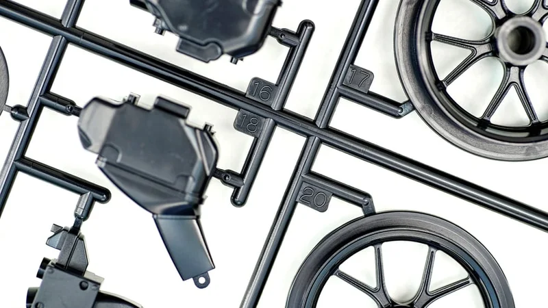
Plastic injection molding is the most common manufacturing technique for plastic parts. Fast, repeatable, and incredibly scalable, the process is used in everything from toys to automotive components.
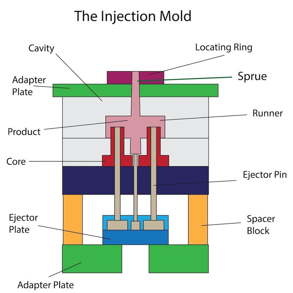
In simple terms, parts are made by forcing molten plastic from an injection molding machine into a mold. But the transfer of the plastic isn’t direct — it’s not like filling up a water balloon at a faucet. Instead, the plastic goes from the nozzle of the injection molding machine through something called a sprue, then a system of runners, then a gate before it enters the mold cavity.
There are several reasons why molds incorporate a sprue, runners, and gates. Firstly, they allow for a controlled and even distribution of plastic — helping to minimize air bubbles, for example — and they also make it possible to include several parts within a single mold, with different runners and gates feeding different cavities.
This article goes over the basics of injection mold sprues, runners, and gates, explaining how they work and listing the different types available.
In short:
A sprue is an inlet that feeds material from the injection machine nozzle to the inside of the mold
Runners are channels that feed material from the sprue to a gate
Gates are very small connecting points between a runner and a mold cavity
What is a sprue?
In an injection molding machine, molten plastic material is forced out of a nozzle via reciprocating screw within a barrel. But where does the material go next? Its ultimate destination is the mold cavity — the empty space between the two halves of the mold — but before it gets there it has to make a small journey.
The first stop on that journey is the sprue, a channel running through the entire thickness of the injection mold (the A plate).
The mouth of the sprue is sealed tightly to the nozzle with a sprue bushing. When a shot of plastic is injected from the injection molding machine into the mold, it passes from the nozzle into the sprue. The sprue is tapered in the direction of the nozzle end, which controls material flow and prevents the formation of air bubbles.
The widest end of the sprue (the end furthest from the machine nozzle) typically connects to a system of runners, which take the molten material further on its journey to the mold cavity. However, in some single-cavity molds — such as molds for some plastic bottles — the sprue leads directly to the mold cavity.
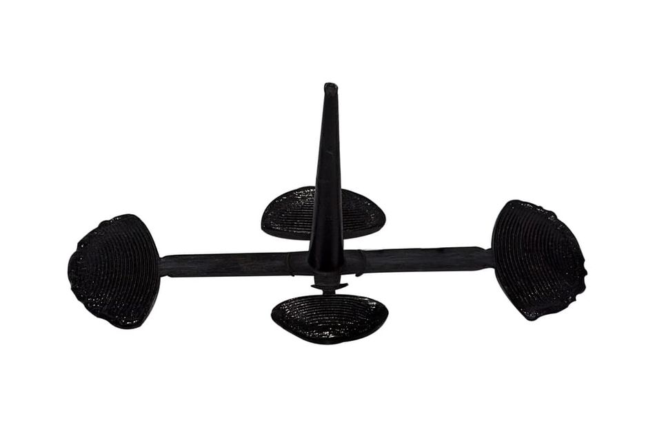
What is sprue (waste material)?
A shot of injection molded plastic fills the mold cavity, sprue, runners, and gates, not just the mold cavity. This means that, after ejection of the finished parts, there may be excess plastic attached to the parts in the shape of the sprue and runners. This material must be trimmed off before the parts can be used. Somewhat confusingly, this excess plastic is referred to as “sprue.”
Recommended reading: Tips to reduce injection molding costs
What is a runner?
Runners are a series of channels connecting the sprue to the various gates opening onto the mold cavity or cavities. They are milled into the surface of one or both of the mold halves, and their function is to transfer the injected molten plastic from the sprue to the mold cavity, where the material will eventually cool and solidify.
There are important differences between an injection mold sprue and its runner system. While the sprue is milled through the entire thickness of the injection mold, passing from the outer surface to the parting line (where the two mold halves meet), the runners are comparatively shallow channels milled into the face of one or two mold halves.
Incorporating runners is a crucial element of mold design, especially in multi-cavity molds, and engineers must consider the length, diameter, and shape of the runners. Ideally, runners should be as short as possible to reduce material waste and cycle times. Thinner runners allow for faster filling but require higher pressure.
The shape of the runner often requires the greatest consideration. In terms of maintaining pressure, the best cross-section shape is round, like a system of pipes. However, this requires milling into both mold halves: a semi-circular channel in each half, meeting at the parting line to form a circular channel. Two alternative shapes, parabola and trapezoid, only require milling into one mold half. While these shapes create a higher pressure drop (and more material waste), they reduce the time and cost of mold production.
In multi-cavity molds, the runners feeding each cavity should be of equal distance from the central sprue to ensure even and simultaneous filling. According to researchers from National Taiwan University, it is important “to fill all cavities at the same instant under the same conditions in order to prevent flashing of the mold and to produce parts of improved and uniform quality.”[1]
If the runner lengths cannot be made equal, it is possible to adjust the diameter of certain lengths of runner — thereby altering the flow rate — in order to compensate and ensure that the cavities still fill up simultaneously.
Hot runner
The information above describes a cold runner system. However, a more advanced alternative — popularized in the 1980s — is the hot runner system.
Unlike a standard cold runner system, a hot runner system incorporates electric heating elements within the mold itself, using individual in-mold nozzles to deliver material to each cavity at the ideal pressure and temperature.
A hot runner system consists of an inlet, a manifold, and individual heated nozzles leading to each cavity. The temperature of the heated elements can be precisely controlled to maintain the material characteristics of the molten plastic. Some hot runner systems have valve gates leading to each cavity, providing even greater control over the mold filling.
Hot runners reduce material waste — there is no sprue material to trim away after molding, for example — and provide excellent part quality. However, the cost of a mold with a hot runner system far exceeds one with a cold runner system.
Recommended reading: Tips for injection molding with high-temperature plastics
Cold runner
The standard cold runner system does not incorporate heating elements within the mold. It is simpler, but more prone to issues like under-filled parts, sink marks, and slower cycle times. Additionally, excess material from the sprue and channels must be removed from the molded parts.
What is a gate?
A gate is a small extension of a runner that leads directly to a mold cavity. It is typically narrower than the runner to which it connects, and is shaped and located in a way that enhances the filling process.
Runners do not typically lead directly into a mold cavity, because the pressure drop of the material moving from runner (narrow) to cavity (wider) would result in slow filling and potential part defects like shrinkage holes. A gate constricts the material flow to build up pressure before the molten plastic enters the cavity.
Gate placement is a big concern for mold designers. If possible, gates should be located in a place where the resulting blemish is not too visible (as the gate must be cut away after molding, and this leaves a mark on the molded part). The injected material should also gate into areas of the cavity with a large wall thickness to reduce sink marks.
Cold runner manual trim gates
The following gate types must be cut away from the molded parts once the injection molding process is finished.
Edge gate
An edge gate or side gate is a simple gate with a rectangular cross-section placed along the parting line of the mold.
Although easy to design and easy to trim after molding, edge gates produce a large amount of pressure loss and can result in part defects like flow marks and air bubbles.
Tab gate
A tab gate consists of an auxiliary tab section that enables material to enter the mold cavity from the side.
The side filling of the tab gate can reduce filling defects, but such gates are harder to trim and may have to be left in place.
Fan gate
A fan gate resembles an edge gate, but with a reverse taper. It “fans out” the closer it gets to the mold cavity.
The fan shape produces a more even filling of the molding material than a simple edge gate, reducing the phenomenon of jetting and the associated part defects. However, because the opening onto the cavity is larger, it is harder to trim and produces a larger blemish on the molded part.
Direct sprue gate
A direct sprue gate is both a sprue and a gate. Molds with direct sprue gates have no runners; instead, the material flows from the nozzle tip through the sprue and directly into the mold cavity.
Such mold designs are very simple, but it is not possible to control the material flow or pressure via additional runners and gates; the injection pressure is dependent on the machine itself. It is also not possible to incorporate multiple cavities into the mold.
Diaphragm gate
A diaphragm gate is a disc-shaped gate incorporated into a section of the part where there is a round gap, such as the opening of a hollow cylindrical part.
Diaphragm gates are good at minimizing flow marks but are fairly difficult to trim, leaving a sharp edge.
Cold runner automatic trim gates
The following gate types are removed automatically after the molding cycle, as the motion of ejection causes them to break.
Tunnel / submarine (sub) gate
A tunnel or submarine gate features an angled tunnel through which plastic flows from the runner to the mold cavity under the parting line.
De-gating is automatic, as the subgate is trimmed from the part when the mold opens up, which can improve productivity. However, these gates are limited in size, and the placement of the gate can cause gas trapping in the mold.
Cashew gate
A cashew gate is a type of tunnel gate that is curved, allowing the material to fill the cavity in a non-visible location below the parting line.
Like tunnel gates, cashew gates are trimmed during ejection, but the de-gating of a cashew is more difficult and can sometimes lead to breakage.
Hot runner gates
The following gate types are only used in hot runner molds.
Thermal gate
A thermal gate is the most common gate type within a hot runner system, directing material from the heated internal nozzle to the mold cavity.
Valve gate
A valve gate is a special type of hot runner gate that uses a moveable pin within the nozzle system to control material flow.
Key takeaways
Sprues, runners, and gates are important elements of an injection mold. They bring the molten plastic from the injection machine to the mold cavity in a thermally efficient manner that minimizes pressure drop, allows for multi-cavity molds, and in some cases enables automatic degating during ejection.
Although the sprue is technically the only essential component of the three — a direct sprue gate is effectively just a sprue without runners or additional gates — runners and gates both have a significant effect on part quality, surface quality, material usage, and cycle times. That being said, product designers only need to understand the basics of these concepts, as it is usually left to the mold manufacturer to decide on sprue, runner, and gate placement.
References
[1] Li CS, Shen YK. Optimum design of runner system balancing in injection molding. International Communications in Heat and Mass Transfer. 1995 Mar 1;22(2):179-88.