Understanding CAD File Types: A Comprehensive Guide for Digital Design and Hardware Engineers
CAD file types are fundamental to modern engineering workflows. This guide explores different CAD file formats, explaining their uses, advantages, and how to choose the right format.
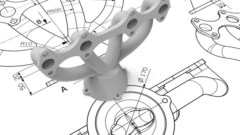
In the world of engineering design, CAD file types play a pivotal role in turning ideas into reality. Every digital design—whether an architectural blueprint, a mechanical part, a circuit board layout, or a chip schematic—is stored in a particular file format. These formats dictate how the design information is encoded, what details can be preserved, and which software can read or edit the file.
For a digital design engineer or hardware engineer, choosing the right CAD file format is as important as the design itself. It can mean the difference between a seamless handoff to manufacturing or a frustrating night of compatibility issues.
This article’s purpose is to demystify CAD file types for digital and hardware design professionals. We will explore the theory behind how different CAD files store information (from simple 2D vectors to complex 3D geometry or electronic connectivity data) and delve into practical considerations like which format to use for a given task.
CAD File Format Fundamentals
Before examining individual formats, it’s important to grasp some fundamental concepts about CAD file types. CAD (Computer-Aided Design) files are digital containers of design information. Depending on the format, a CAD file can hold anything from simple 2D drawings to complex 3D geometry, assembly relationships, material properties, or manufacturing data. Below are some key theoretical concepts to understand.
Native and Neutral
Native formats are proprietary to a specific CAD software. They store the full fidelity of the model including parametric features, design history, and other software-specific data. Examples: .dwg (AutoCAD drawing), .sldprt (SolidWorks part), .prt/.asm (PTC Creo or NX part/assembly), .schdoc/.pcbdoc (Altium schematic/PCB). Native files are optimal for editing in the originating tool but often not readable elsewhere without conversion.
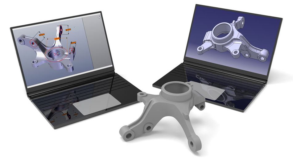
Neutral formats are vendor-independent standards designed for interoperability. They capture the geometry and basic structure of designs in a generalized way so that different software can import/export them. Examples: STEP and IGES for 3D models, DXF for 2D drawings. The specifications for neutral formats are usually public and maintained by standards organizations or consortia (e.g., IGES by NIST, STEP by ISO.[1] Neutral files are ideal for sharing models between different CAD programs or with clients/manufacturers who don’t have the native CAD software.
2D and 3D
2D CAD files store flat drawings (X-Y coordinates) with layers for organization, using vector entities like lines and text. Formats like DWG and DXF are ideal for schematics and machining profiles. 3D CAD files, on the other hand, define objects in three dimensions (X, Y, Z) using:
B-Rep (Boundary Representation): Uses mathematically exact surfaces for precise modeling, common in parametric CAD (e.g., SolidWorks, CATIA). Formats like STEP and Parasolid store B-Rep data.
Polygonal Mesh: Approximates surfaces with triangles (e.g., STL), useful for visualization but lacking precision.
Some formats, like the Siemens JT format, support both methods, while others (IGES, STL) are exclusive to one.
The Contents of a CAD File
CAD files store more than just geometry; they also contain topology, assembly structure, and metadata.[2] In B-Rep models, topology defines how surfaces connect, ensuring a solid, editable shape. Different formats handle topology in unique ways; for example, IGES lacks explicit edge definitions, making it harder to reconstruct connectivity. Proper topology is essential for seamless imports and edits.
Complex designs often involve multiple parts, managed through an assembly structure. Some formats, like STEP, can store entire assemblies in a single file, while others, such as SolidWorks, use separate files for each part and the assembly structure. Not all formats support assemblies—STL and IGES lack built-in multi-part organization, while STEP and 3D PDF do.
Metadata enhances CAD files with information beyond shape, such as part names, materials, and annotations. Some formats store minimal data—STL contains only a triangle mesh with no scale or color—while richer formats like STEP include material properties and design intent. The 3MF format, designed for 3D printing, embeds colors, textures, and print settings, offering greater versatility than STL.
Why So Many CAD Formats?
The variety of CAD file formats stems from specialized engineering needs and historical development. Mechanical, architectural, and electronic CAD systems each optimized their formats for specific applications. Proprietary formats, such as AutoCAD’s DWG, became industry standards, while neutral formats like IGES and STEP emerged to facilitate data exchange. Legacy formats persist despite newer alternatives because they are widely used and deeply integrated into workflows.
In essence, CAD file diversity reflects the varied requirements of different industries. Whether capturing a simple 2D schematic or a detailed 3D assembly, each format serves a specific role. Understanding these differences helps in choosing the right file type for the task at hand.
Common 2D CAD File Formats
When it comes to two-dimensional CAD data, the most prominent formats originate from Autodesk’s AutoCAD, given its long history (since the early 1980s) in CAD drafting. Two key file types dominate 2D CAD.
DWG
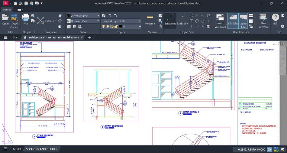
DWG is AutoCAD’s native file format, introduced in 1982. It stores 2D and limited 3D data efficiently in a compact binary format. Widely used in architecture and mechanical design, DWG files contain vector entities, layers, and annotations. While Autodesk keeps DWG proprietary, non-Autodesk programs can read it via reverse-engineered libraries, though compatibility issues may arise. Autodesk updates DWG versions periodically, requiring users to save in older formats for backward compatibility.
DXF
DXF, also from Autodesk, was created as a text-based alternative to DWG for data exchange. Its ASCII format makes it larger but easily readable and widely supported across CAD, CNC, and graphic software. DXF became the standard for 2D CAD interoperability, enabling seamless integration with laser cutting, PCB design, and other applications.
Others
Beyond DWG and DXF, other 2D CAD formats include DGN, used in civil engineering with MicroStation, and PDF, which serves as a universal, non-editable format for sharing CAD drawings. SVG, a web-standard vector format, is occasionally used for simple 2D profiles. In electronics, schematic files store circuit diagrams, with formats varying by ECAD software, though EDIF serves as a neutral option.
Common 3D CAD File Formats
Three-dimensional models introduce more complexity than 2D drawings, and correspondingly there are more file formats to consider. We can classify 3D CAD file types into a few subcategories:
Neutral 3D exchange formats: e.g. STEP, IGE.
Native 3D CAD formats: e.g. CATPart (CATIA), SLDPRT (SolidWorks), IPT (Inventor)
Kernel formats: Parasolid (.x_t/.x_b), ACIS (.sat)
Polygonal mesh formats: e.g. STL, OBJ, 3M
Visualization/lightweight formats: e.g. 3D PDF, JT
STEP: Standard for the Exchange of Product Model Data (ISO 10303)
STEP, governed by ISO 10303, is the leading neutral format for 3D CAD exchange. Introduced in 1994 as a successor to IGES, it supports full 3D solids, assemblies, and metadata like materials and tolerances. It encodes B-Rep geometry, assembly hierarchies, and attributes in an ASCII format, though not human-readable. STEP is divided into Application Protocols (AP), such as AP203/214 for mechanical design and AP242 for PMI.
Used widely for cross-CAD collaboration, STEP preserves geometry but not feature history. It has largely replaced IGES due to its robustness and continued development, making it the preferred format for modern workflows.
Recommended reading: The STEP File Format: A Technical Guide
IGES: Initial Graphics Exchange Specification
IGES, introduced in 1980, was the first widely adopted neutral CAD format, mandated by some government agencies. It supports 2D drawings, wireframes, and surfaces but lacks robust solid modeling. Often, IGES files require fixing due to missing faces or gaps.
An ASCII-based format, IGES saw its last update in 1996 and is now obsolete. While some older systems still use it, STEP is the preferred alternative for 3D data exchange due to better support and continued development. Use IGES only when necessary, expecting potential cleanup.
Native 3D CAD Formats (Briefly)
Every major 3D CAD software has its own format, which is often a closed binary file:
SolidWorks: .sldprt (part), .sldasm (assembly)
CATIA: .CATPart, .CATProduct
PTC Creo (Pro/E): .prt, .asm (and older .neu neutral files)
Siemens NX: .prt (different from Creo’s despite same extension)
Autodesk Inventor: .ipt (part), .iam (assembly)
Rhino: .3dm (which is actually open/spec published)
SketchUp: .skp
These formats store feature trees, constraints, and all the rich data of the design. But sharing those with someone who doesn’t have the same software is problematic, hence the use of neutrals like STEP.
Some CAD systems can directly open another’s native files through interoperability agreements or libraries (e.g., some can directly open SolidWorks files if licensed to do so), but this is case by case.
Parasolid and ACIS (Kernel Formats)
Parasolid (Siemens) and ACIS (Spatial/Dassault) are modeling kernels used in many CAD programs. Parasolid supports formats like .x_t (text) and .x_b (binary), while ACIS uses .sat (text) and .sab (binary). These formats enable seamless transfers between software using the same kernel, such as SolidWorks to NX, preserving geometry and metadata.
While Parasolid and ACIS are widely supported, they function as just another format in non-kernel-based systems. If compatible, Parasolid often transfers solids more reliably than IGES. Otherwise, STEP remains a strong alternative for interoperability.
STL: Stereolithography
STL is the dominant format in 3D printing, created in 1987 by 3D Systems. It represents surfaces as tessellated triangles without units, metadata, or built-in validity checks. STL files can be ASCII (large) or binary (smaller) and typically store single solids. Despite its simplicity and widespread support, STL has limitations like lack of scale, color, and multi-material support.
Alternatives include 3MF, an XML-based format with unit scale, colors, and multi-material support, and OBJ, which allows color and textures.[3] STL remains standard for engineering use, but 3MF is gaining traction for more complex 3D printing needs.
Recommended reading: Understanding 3D Printer File Formats (STL, OBJ, 3MF, and more)
Others
There are numerous other formats, but a few worth noting for completeness:
OBJ: Mentioned above, widely used in 3D modeling and animation, not so much in mechanical CAD but sometimes used for things like importing a 3D scan mesh.
PLY: Polygon file format, often output by 3D scanners (includes vertex color data typically).
GLTF/GLB: Modern 3D transmission format by Khronos for web and AR, can contain meshes, materials, animations. More for visualization, not for CAD design.
3D PDF (U3D or PRC inside): PDF files can embed 3D models using U3D or PRC formats. Engineers sometimes use 3D PDFs to share a viewable 3D model with someone who only needs to inspect it (Adobe Reader can rotate the model). It’s not meant for editing or precise data exchange, just convenient viewing.
JT: A lightweight 3D format from Siemens PLM, often used in automotive/aerospace for sharing large assemblies. It can include both mesh and precise data and is tuned for visualization performance.
Electronics CAD Formats
Electronics CAD formats differ from mechanical CAD because they represent not just physical geometry but also electrical connectivity. These formats are essential for designing PCBs (Printed Circuit Boards) and ICs (Integrated Circuits), handling schematics, layouts, and manufacturing data.
PCB Formats
PCB design files contain copper traces, component placements, and layers. Formats include:
Gerber (RS-274X): Standard for PCB manufacturing, defining copper layers, solder masks, and silkscreen.
ODB++: A richer alternative to Gerber, including netlists and stack-up data.
IPC-2581: An open, standardized PCB format integrating fabrication, assembly, and test data.
IC & Semiconductor Formats
These handle microchip layouts and verification, emphasizing nanoscale precision.
GDSII: The primary format for IC masks, used in photolithography.
OASIS: A more compact IC layout format replacing GDSII.
SPICE: Describes circuit behavior for simulations rather than physical design.
Unlike 3D CAD formats (STEP, IGES), electronics formats must encode electrical properties, netlists (connections), and layer-based fabrication data. They are optimized for two-dimensional layouts, whereas mechanical CAD focuses on solid geometry and assembly constraints.
Recommended reading: PCB Layout: A Comprehensive Guide
Using CAD File Types Effectively
For any hardware engineer, knowing how to use different CAD file formats effectively is hugely important. First, always use the native format when designing to maintain parametric data and design history. For sharing, export to a neutral format like STEP or Parasolid for compatibility with other tools. For example, design in SolidWorks and export as STEP to send to a supplier using CATIA.
Understand what format your partner needs. A CNC shop may accept STEP or a dimensioned drawing, while a 3D printing service often requires STL or 3MF, especially for multi-material prints. For PCB manufacturing, Gerber files are common, while assembly houses require Centroid files and BOMs. An IC foundry typically uses GDSII.
Be mindful of version compatibility when sharing files. Ensure the recipient can open your file, and when in doubt, revert to neutral formats. Always inspect exported files for accuracy, as geometric errors may occur during conversion. For example, use a viewer to check if parts align correctly in a STEP file.
Finally, to protect intellectual property, consider simplifying the files you send. For example, use a dumb solid in STEP format to limit access to design details. Use clear naming conventions when sharing multiple files to avoid confusion. Finally, leverage newer formats like 3MF or IPC-2581 when possible for more complete and efficient data exchange.
Conclusion
Understanding and selecting the right CAD file formats is important for smooth collaboration and accurate data exchange. Native formats preserve full design details, while neutral formats like STEP and IGES ensure compatibility across different systems. Always consider the recipient's needs, verify file accuracy, and protect intellectual property when sharing files. Staying informed about each format's strengths and limitations ensures efficient, error-free communication across the entire design and manufacturing process.
Frequently Asked Questions
Why are there so many CAD file types?
There are many CAD file types because different industries and applications require specific features, such as design history, geometry precision, or material properties. Each format caters to unique needs like 3D modeling, electronics, and manufacturing processes, leading to a variety of options for compatibility, flexibility, and functionality.
What’s the difference between native and neutral CAD formats?
Native formats are specific to a particular CAD software and preserve all design details, including parametric data and features. Neutral formats like STEP or IGES, on the other hand, are standardized for data exchange across different CAD systems, sacrificing some design features for broader compatibility.
When should I use STL instead of other formats?
STL is best used for 3D printing and rapid prototyping since it focuses on surface geometry using triangular meshes. It’s ideal for creating physical models but lacks details like color, material properties, or scale, which may be needed for more advanced manufacturing processes.
How do I ensure compatibility with different CAD systems?
To ensure compatibility, use neutral formats like STEP or IGES, which are widely supported across various CAD platforms. If possible, export files in these formats rather than native ones, and always check the file for accuracy before sharing with collaborators or manufacturers.
References
[1] Hogan MD, Carnahan LJ, Carpenter RJ, Flater DW, Fowler JE, Frechette SP, Gray MM, Johnson LA, McCabe RM, Montgomery D, Radack SM. Information technology measurement and testing activities at NIST. Journal of Research of The National Institute of Standards and Technology. 2001 Feb 1;106(1):341.
[2] Bharadwaj A, Xu Y, Angrish A, Chen Y, Starly B. Development of a pilot manufacturing cyberinfrastructure with an information rich mechanical cad 3D model repository. InInternational Manufacturing Science and Engineering Conference 2019 Jun 10 (Vol. 58745, p. V001T02A035). American Society of Mechanical Engineers.
[3] Liu R, Yang W, Li H, Wang Y, Wang H. Color printing based on 3MF: Color diffusion from the surface to the interior of voxel model. Engineering Reports. 2023 Dec;5(12):e12623.


